Attitude problems

196 görüntüleme
İlk okunmamış mesaja atla

Giulio Berti

okunmadı,
14 Haz 2012 02:52:1614.06.2012
alıcı uavde...@googlegroups.com
Hi,
finally I'm running Matrixpilot on my board!
Finally I can use mavlink to visualize the attitude of my board (thanks Matt!) and I discovered some problems:
-Starting from a rest position, if I move the board, after returning in the same position, the output is not the same as before. As you can see from "Attitude errors.pdf" after the movement the output has got an oscillatory behaviour. Why it happens this? Could it be a wrong setup of the sensors axis in respect of the board?

-Also if the board is receiving data from the gps (commit_gps_data() is called and gps_nav_valid() returns true) QgroundControl tells me that my airplane is at 0 lat 0 lon.

options.h I'm running my branch, rev 1572

Any thought?

In 2 weeks I'll leave China, I hope that I'll be able to fly with Matrixpilot onboard! My plane is waiting for me in Italy :) 

Kind regards,

Giulio

Attitude errors.pdf
Attitude errors.csv

José Carlito de Oliveira Filho

okunmadı,
14 Haz 2012 05:48:4514.06.2012
alıcı uavde...@googlegroups.com

Hi,

This can be the gyros that are not initialized.
In one of my planes i have to start udb first then start the motor esc, otherwise that heappens to me also.

try to turn your board on whithout nothing connected to it, then you connect your peripherals, zigbee,etc.

Hope.it helps

Carlito

Peter Hollands

okunmadı,
14 Haz 2012 05:49:1714.06.2012
alıcı uavde...@googlegroups.com
Guilio,
 
It is super to hear that you have a modified version of recent trunk running on your board.
 
I think Bill will probably be best placed to answer your quesions about oscillations.
Can you confirm that the scale for time is in whole seconds ?
i.e. the period of the oscillations is about 200 seconds ?
 
With regard to the GPS not coming out in QgroundControl. First, we must remember that you are using the NMEA GPS code.
I don't think that mmany of us have experience of that yet. Are you certain that the GPS messages for LAT / LONG are coming through ?
Can you print out some telemetry using SERIAL_UDB_EXTRA, as this is much more mature code ?
What are you using to view the GPS positionsn in QGround Control ? Because the map is using IMULocation not the direct GPS position.
The message is called something like GLOBAL_POSITION_INT, and it runs at 8 times / second. The mavlink_options.h has to be edited if your
want the raw GPS position to be sent to  QGroundControl. (
 
Best wishes, Pete

Giulio Berti

okunmadı,
14 Haz 2012 06:28:1714.06.2012
alıcı uavde...@googlegroups.com
Hi Pete,

The numbers are mS thus, yes the period of the oscillation is about 200s. Watching it better i noticed that they seems to be sinusoids with the same amplitude shifted in phase of 120°.

I'm quite sure that the lat/long messages are coming through, I checked it piloting a led inside the state machine, but I'll check again using the debugger and SUE.
Thanks for the explaination of GLOBAL_GPS_INT, that for sure was a problem.
I checked my mavlink_options.h, should I expect the GPS_RAW data with this setting?
#define MAVLINK_RATE_RAW_SENSORS 2 /* IMU_RAW, GPS_RAW, GPS_STATUS packets. | */

This night I'll do other tests. Meanwhile thank you really much for the help!

Giulio

Giulio Berti

okunmadı,
14 Haz 2012 10:01:4914.06.2012
alıcı uavde...@googlegroups.com
Hi!
I'm super happy!
I did more tests with SUE, the GPS is sending data and the udb seems to read them correctly :D
Sorry If I'm so happy but this is the first time I can create a kmz file using my board, Is really a great satisfaction!

The board was still all the time long, the GPS is so imprecise because the board was sitting on the balcony.
(i have to check why svs is always just 1)

Thank you all very much,
Giulio
SUE1.kmz
SUE1.txt

Peter Hollands

okunmadı,
14 Haz 2012 11:18:0314.06.2012
alıcı uavde...@googlegroups.com
Giulio,

Super to see your board start to work. Thanks for sharing the telemetry.

The CPU is reported as being at 61%. That could be complete and utter Tosh ( i.e. lies).
Or you may need to look into that. The UDB4 is running at about 10 percent when using SUE.
Of course it may be exactly the issue that Bill asked us to remember in another post this week.
 i.e. ensure that you are using
-lib-legacy correctly. (An incorrect library for sprintf can eat up CPU when using telemetry).

It is also nice to see BOARD number 8 existing for MatrixPIlot in the telemetry.
F14:WIND_EST=1:GPS_TYPE=6:DR=1:BOARD_TYPE=8:

Anyway, glad you are delighted.

Best wishes, Pete

Giulio Berti

okunmadı,
14 Haz 2012 11:31:5014.06.2012
alıcı uavde...@googlegroups.com
Pete,

That is for sure a problem of mine, My board is running @80MHz and I didn't watch yet at the cpu usage timer (n5 right?)

I think that I was using the yaw gyro inverted, now my sensors are pointing like the picture of the plane here, Is that right?
With this configuration, the situation is slightly improved:
-the gyro drift as it should (8 deg/min)
-after a movement of the board, the attitude is the same as before and this is great.
-the oscillations are inside +-0.07rad, almost 4°

Thanks again!
capture3.csv
Attitude errors2.pdf
Attitude errors3.pdf
Attitude errors4.pdf
capture2.csv

Giulio Berti

okunmadı,
14 Haz 2012 13:10:4114.06.2012
alıcı uavde...@googlegroups.com
I fixed the cpu usage,
CPU_LOAD_PERCENT before was 16*100, mine should be 16*40.
Just for fun I generalized it the formula is quite complicated otherwise there were an overflow in the calculation.
#define CPU_LOAD_PERCENT 16*CLK_PHASES*((390625*4096)/FREQOSC)

The cpu usage now is 24% both using mavlink and sue, can the nmea gps and the i2c imu cause this?

Kind regards,

Giulio

Peter Hollands

okunmadı,
14 Haz 2012 14:15:4814.06.2012
alıcı uavde...@googlegroups.com
Hi Giulio,

That calculation (line 45)  seems to work correctly when put into a spreadsheet.
(There is a small discrepancy between our hardcoded numbers for FRC ).

I'll check with another core developer to confirm that they agree that this definition should go into the code,
and replace the current hard coded numbers in background.c .

Best wishes, Pete

William Premerlani

okunmadı,
14 Haz 2012 20:28:5314.06.2012
alıcı uavde...@googlegroups.com
Hi Giulio,

I see that the team, especially Peter, has helped you get your board working. Way to go!!
Regarding the question about "oscillations", I think that what you are seeing is a "false" rotation rate at a fixed rate about some axis. Such a rotation will cause all of the elements of matrix to oscillate about an average value. I think you said the period was 200 seconds. So, this is a rotation rate of 360 degrees/200 seconds = 1.8 degrees per second.

I am not sure how it arose, but I note from reading the rest of the thread that you have things working now, so I will leave it at that.

Bill

Giulio Berti

okunmadı,
1 Tem 2012 14:10:461.07.2012
alıcı uavde...@googlegroups.com
G'day Pete,
I changed the clock from 80 to 32Mhz, and the cpu usage is exactly the same... Am I missing something? 

Regards,
Giulio

Peter Hollands

okunmadı,
1 Tem 2012 17:29:501.07.2012
alıcı uavde...@googlegroups.com
Hi Giulio,

I would defer to Mark Whitehorn, or Bill on changing clock rates, as they have done that before. Ben, Robert or Matt might also be able to help.

What I do know, is that you would need to probably change quite a few statements across the code, and would need a good understanding of all of the timers, and how they are set, if you change the clock rate.

When you say you changed from 80Mhz to 32Mhz, I'm not sure what of all the lines in the code that you changed.

Best wishes, Pete


--

Giulio Berti

okunmadı,
1 Tem 2012 18:25:231.07.2012
alıcı uavde...@googlegroups.com
Hi,
I'll double check everything, but theoretically I changed the hard coded frequency dependent values with formulas -> I'll check again the formulas.
I noticed later that running at 32MHz I can read the digital imu up to 1800KHz, not 2000KHz as before. Reading it at 1800KHz the cpu load is very close to 50%.
Do you ever seen the cpu load higher than 50%? Is it possible that @32MHz the right value of CPU_LOAD_PERCENT is 3200 instead of 1600?

Regards,
Giulio

PS: I'm finally back in Italy now I can do fly tests! I got the 2 mode switch working, I checked the waggles of the servo during the startup, the nmea parser seems to be working! I'm almost ready to do an assisted fly, but first I need to solve the attitude problem described previously in this thread and I want the HILSIM working... 

Peter Hollands

okunmadı,
2 Tem 2012 04:38:012.07.2012
alıcı uavde...@googlegroups.com
Giulio,

Thanks for your comments and review.

 I think that CPU Load could be out by 50 percent.  The reason it was wrong is the comment in the code says the timer is drivern from the Chrystal clock. But it is not. Timer 5 is driven from Fosc / 2 otherwise known as Fcy. I have discovered that by re-reading the chapter on timers in the dspic33F family reference manual.

I've made and addendum to this spreadsheet with my current calculations. Let's review this issue with a couple of other developers for their view before making the change.

Best wishes, Pete


--

Claudio Carbone

okunmadı,
2 Tem 2012 05:34:192.07.2012
alıcı uavde...@googlegroups.com

Peter and Giulio,

irrespective of what frequency source is "internally" used by the micro, I suspect the calculations would not show anything different.


Problem is that everything is driven by internally generated timers.

Every timer scales with the FCY which is a function of the core frequency.

So if you scale the PLL you are effectively scaling the main frequency drive for the timers as well.

So I suspect that everything will function just the same, but totally unaware of the real frequency.

That's because there is nothing actually telling the MCU how fast it is really working: if your source is relative, everything scales accordingly.

Moreover every internal frequency threshold, post-scaler, whatever, would be adamant to the change: a counter would still count its numer of iterations, same for interrupts.

The only way to scale the cpu clock, is to adjust timers pre/post scalers and/or periods to maintain the previous frequency.

But that's something that has to be done in code.


Claudio


--

Peter Hollands

okunmadı,
2 Tem 2012 13:21:592.07.2012
alıcı uavde...@googlegroups.com
Guilio,

I ran an emprical test just now on the CPU loading algorithm.

I found the lowest priority interrupt in MatrixPilot and put it into an infintite loop. And then watched the cpu loading to see what it moved to.

The answer is 95% cpu load, when all interrupts are firing all the time. Which is approximately correct, and  disproves the hypothesis that "CPU_LOAD_PERCENT might possibly be 3200 instead of 1600".

The 5% error can be explained by the fact that  the CPU_LOAD_PERCENT should be 1677 (Thanks for making me re-check all the sums today).  1600 was the original figure that is in the code now. 1677 / 1600 is 0.95 or a 95 percent loading being shown in correctly.

So, yes, I have now seen more than a 50% loading, and there is a small correction to make the CPU load 5% more accurate.

I enclose a small patch that I used to check the cpu loading at 100%. Once applied, you need to start MatrixPilot and record telemetry. When the first GPS position arrives, the routine called udb_background_triggered is called,
and there I have put in the infifinte loop, so that this interrupt never exits. So the CPU load will be 100%. There will  of course be no waggles when the first GPS arrives with my test as I've basically stopped the GPS code completing.

You should see something like this in the telemetry:-

F2:T0:S100:N0:E0:A0:W0:a5564:b-15360:c1240:d15406:e5526:f-722:g258:h1412:i16320:c0:s0:cpu9:bmv0:as0:wvx0:wvy0:wvz0:ma34:mb214:mc464:svs0:hd0: p1i2939:p2i3047:p3i3047:p4i3001:p5i2013:p6i2953:p7i118:p8i0:p9i0:p10i0:p1o2939:p2o3047:p3o3047:p4o3001:p5o0:p6o0:p7o0:p8o0:p9o0:p10o0:imx0:imy0:imz0:fgs800:ofc0:tx0:ty0:tz0:G0,0,0:stk0:

F2:T0:S100:N0:E0:A0:W0:a5500:b-15380:c1272:d15430:e5460:f-746:g276:h1448:i16318:c0:s0:cpu92:bmv0:as0:wvx0:wvy0:wvz0:ma38:mb212:mc466:svs0:hd0: p1i2939:p2i3047:p3i3047:p4i3001:p5i2013:p6i2954:p7i117:p8i0:p9i0:p10i0:p1o2939:p2o3047:p3o3047:p4o3001:p5o0:p6o0:p7o0:p8o0:p9o0:p10o0:imx0:imy0:imz0:fgs800:ofc0:tx0:ty0:tz0:G0,0,0:stk0:

F2:T0:S100:N0:E0:A0:W0:a5436:b-15400:c1320:d15452:e5392:f-766:g286:h1500:i16312:c0:s0:cpu92:bmv0:as0:wvx0:wvy0:wvz0:ma38:mb212:mc460:svs0:hd0: p1i2939:p2i3047:p3i3047:p4i3002:p5i2013:p6i2953:p7i117:p8i0:p9i0:p10i0:p1o2939:p2o3047:p3o3047:p4o3002:p5o0:p6o0:p7o0:p8o0:p9o0:p10o0:imx0:imy0:imz0:fgs800:ofc0:tx0:ty0:tz0:G0,0,0:stk0:

F2:T0:S100:N0:E0:A0:W0:a5372:b-15418:c1368:d15474:e5324:f-792:g300:h1552:i16308:c0:s0:cpu92:bmv0:as0:wvx0:wvy0:wvz0:ma34:mb208:mc462:svs0:hd0: p1i2940:p2i3047:p3i3047:p4i3001:p5i2014:p6i2953:p7i118:p8i0:p9i0:p10i0:p1o2940:p2o3047:p3o3047:p4o3001:p5o0:p6o0:p7o0:p8o0:p9o0:p10o0:imx0:imy0:imz0:fgs800:ofc0:tx0:ty0:tz0:G0,0,0:stk0:

F2:T0:S100:N0:E0:A0:W0:a5304:b-15438:c1402:d15498:e5256:f-796:g300:h1584:i16304:c0:s0:cpu92:bmv0:as0:wvx0:wvy0:wvz0:ma38:mb212:mc466:svs0:hd0: p1i2940:p2i3047:p3i3047:p4i3001:p5i2014:p6i2953:p7i117:p8i0:p9i0:p10i0:p1o2940:p2o3047:p3o3047:p4o3001:p5o0:p6o0:p7o0:p8o0:p9o0:p10o0:imx0:imy0:imz0:fgs800:ofc0:tx0:ty0:tz0:G0,0,0:stk0:

F2:T0:S100:N0:E0:A0:W0:a5218:b-15462:c1464:d15526:e5170:f-792:g286:h1640:i16298:c0:s0:cpu95:bmv0:as0:wvx0:wvy0:wvz0:ma36:mb208:mc464:svs0:hd0: p1i2940:p2i3047:p3i3047:p4i3001:p5i2014:p6i2954:p7i117:p8i0:p9i0:p10i0:p1o2940:p2o3047:p3o3047:p4o3001:p5o0:p6o0:p7o0:p8o0:p9o0:p10o0:imx0:imy0:imz0:fgs800:ofc0:tx0:ty0:tz0:G0,0,0:stk0:

F2:T0:S100:N0:E0:A0:W0:a5176:b-15472:c1504:d15542:e5118:f-816:g300:h1684:i16294:c0:s0:cpu95:bmv0:as0:wvx0:wvy0:wvz0:ma32:mb210:mc466:svs0:hd0: p1i2939:p2i3047:p3i3047:p4i3002:p5i2014:p6i2953:p7i117:p8i0:p9i0:p10i0:p1o2939:p2o3047:p3o3047:p4o3002:p5o0:p6o0:p7o0:p8o0:p9o0:p10o0:imx0:imy0:imz0:fgs800:ofc0:tx0:ty0:tz0:G0,0,0:stk0:


I am very grateful that you are re-implementing MatrixPilot on another board, as it is providing the opportunity for someone to completely check and re-evalute some parts of our code.

Best wishes, Pete


--

gpsParseCommon.c.patch

Giulio Berti

okunmadı,
6 Tem 2012 04:22:056.07.2012
alıcı uavde...@googlegroups.com
Pete,

sorry if I'm not responding you, I'm very busy with my exams :(
I noticed that I'm already using the -legacy-libc options, I'll do more tests during the next week!

Regards,
Giulio

Giulio Berti

okunmadı,
10 Tem 2012 05:37:2710.07.2012
alıcı uavde...@googlegroups.com
Pete,
You are right, 1677 @32MHz is correct also for me.

Now I have to understand why my cpu usage is so high... I'll comment all the indicate_loading_inter lines, and check one interrupt at a time.

I noticed that using mavlink, I have a send loss constant at 24-25% (also using the ftdi).
Thank you very much for your help!

Giulio
CPUtest3.txt

Giulio Berti

okunmadı,
10 Tem 2012 06:31:4110.07.2012
alıcı uavde...@googlegroups.com
The situation is like this:
CPU loading:
_T1Interrupt 3%
_TTRIGGER <1%
_THEARTBEAT 2%
_IC1Interrupt <1% // Using PPM
_T4Interrupt 3% // Isn't a little bit high? (5 servo)
_U1TXInterrupt <1% // Xbee tx using mavlink
_U1RXInterrupt <1%
_U2TXInterrupt <1% // board tx gps rx
_U2RXInterrupt <1%
event trigger <1%
_MI2C1Interrupt 3% // I2C imu (reading @40Hz, it's 17-18% reading at 1,5KHz)
_DMA0Interrupt 23% // Found! Actually I'm not using the adc yet, I'll use it to read the voltage of the board supply, the voltage and the current of the motor battery and fot the external temperature.

Regards,
Giulio 

Giulio Berti

okunmadı,
10 Tem 2012 17:42:5610.07.2012
alıcı uavde...@googlegroups.com
The reason of the high cpu usage in the adc interrupt was that  AD1CON3bits.ADCS was 11 and NUM_AD_CHAN  was 4 so the frequency of the dma interrupt was:
DMA_HZ = Fcy/((ADCS+1)*14*NUM_AD_CHAN) = 23.8KHz I changed ADCS to 55 to get a 5.1KHz freq.

Now I'm trying to solve my attitude problem. I'm reading the IMU @1KHz, faster speed are unstable.
Although the raw values of the gyro are pretty stable (20LSB change over a range of +-32000) the roll and pitch are again crazy...  
Could it be a bad scaling of the gyro or the accelerometer? I'm quite sure to have made confusion with  SCALEGYRO and SCALEACCEL.

I faced this problem all the day long  and now I'm out of ideas :(

Kind regards,
Giulio
long log4.csv

Giulio Berti

okunmadı,
11 Tem 2012 19:50:0611.07.2012
alıcı uavde...@googlegroups.com
Hi,
thanks to this discussion I corrected the scale of the accelerometer, I'm still not sure about the XACCEL_SIGN YACCEL_SIGN and ZACCEL_SIGN.
From #define DEGPERSEC ((long long)98.3/SCALEGYRO), and considering my sensor resolution 14.375, I calculated a value for SCALEGYRO of 6.8383, but actually it's 4 times higher, the correct one seems to be 6.8383/4. Is my datasheet wrong?

Running my branch at revision 1622 I did a test: starting with the board flat on the table, after the calibration, i turned it -90° in respect to the pitch axis and I left it as it were. The result is interesting: after a transition the value of the roll is constant at a complete different value: +20° or so... which is quite different from -90!

Note that disabling the PI correction, the values of the pitch and the roll drifts, but the attitude is estimated almost correctly. So probably the problem is in the information used for the PI correction.

Can anyone help me?

Thank you :)

Giulio 
attitude error.pdf
attitude error.csv

William Premerlani

okunmadı,
11 Tem 2012 20:26:3011.07.2012
alıcı uavde...@googlegroups.com
Hi Giulio,

Your gyro spec sheet is probably ok.

SCALEGYRO is not gyro sensor resolution, its simply a scale factor relative to the first gyro I used in UDB1. The way SCALEGYRO works is a legacy of the first gyro that I used in "UDB1", which did not have SCALEGYRO, the gain was hardwired into the code. After that, SCALEGYRO was introduced to scale things in multiples of the first gyro.

SCALEGYRO is proportional to the AD reference voltage, and inversely proportional to the gyro sensitivity.

That is, SCALEGYRO = 4.95 * (Vref/3.3) * ( 2 / sensitivity ),

Where Vref is the AD reference voltage in volts, and sensitivity is the gyro sensitivity, in millivolts per degree per second.

So, for example, with a reference voltage of 3.3 volts and a sensitivity of 2 millivolts per degree per second, SCALEGYRO comes out to be 4.95.

From the your description of your test results (I assume the roll pitch yaw demo) it sounds like you may have a problem with signs and axes. Good luck with that, sorting that out can be a challenge. If you are using MatrixPilot, you will need to define axes and signs to map the physical accelerometer and gyro axes and signs into "UDB" frame of reference. For more information on that, see this wiki entry.

Best regards,
Bill

--

William Premerlani

okunmadı,
11 Tem 2012 20:31:3411.07.2012
alıcı uavde...@googlegroups.com
Hi Giulo,

By the way, the equation I gave you for SCALEGYRO comes out to be:
3*(Vref/sensitivity), with Vref in volts, and sensitivity in millivolts.

In UDB1, the reference voltage was 5 volts, and the sensitivity was 15 millivolts/degree/second. So for that gyro, SCALEGYRO equals 1.

The UDB1 had a 75 degree/second gyro.

Best regards,
Bill

Peter Hollands

okunmadı,
12 Tem 2012 03:57:2512.07.2012
alıcı uavde...@googlegroups.com
Guilio

Just to add some extra thoughts besides Bill's ....

You say you are rotating around the pitch axix by -90 degrees. (The UDB X Axis) That means you are either pointing straight up or straight down (I forget which way is negative for now).  That is a tricky (if not bad) place to check for a roll or yaw angle using Eulers in your system. The Yaw and Roll (with respect to the Earth) will become incredibly sensitive to tiny movements of the board away straight up / down.

It is probably easier for straight up and straight down, to examine the Direction Cosine Matrix numbers, rather than covert to Eulers. If is a nice feeling to actually understand the 9 DCM numbers in SERIAL_UDB_EXTRA.

Best wishes, Pete


--

Giulio Berti

okunmadı,
12 Tem 2012 04:34:5712.07.2012
alıcı uavde...@googlegroups.com
Hi Pete, Bill

I drawn a 3D sketch to better visualize how the sensors are rotated in respect to the board.
How should I select the axis?

In respect of the aviation convention - airplane I thought it should be:
udb_xrate               gyroMeasureRaw[1];
udb_yrate               gyroMeasureRaw[0];
udb_zrate               gyroMeasureRaw[2];
#define XRATE_SIGN -
#define YRATE_SIGN -
#define ZRATE_SIGN -

udb_xaccel             accMeasureRaw[1];
udb_yaccel             accMeasureRaw[0];
udb_zaccel             accMeasureRaw[2];
#define XACCEL_SIGN -
#define YACCEL_SIGN -
#define ZACCEL_SIGN -

What do you think? 

@Pete: I'll record some SUE doing the same test again.

Best regards,
Giulio
UDB coordinate system.png
UDB coordinate system.skp

Giulio Berti

okunmadı,
12 Tem 2012 05:04:2612.07.2012
alıcı uavde...@googlegroups.com
Hi again,

attached you find the same test but with sue recorded.

@Bill: I'm already using Matrixpilot, when we'll solve this problem, I'll be finally ready to fly!

Thanks for your help :)

Giulio

On Thursday, 12 July 2012 09:57:25 UTC+2, Pete wrote:
roll test.txt

Peter Hollands

okunmadı,
12 Tem 2012 15:40:3112.07.2012
alıcı uavde...@googlegroups.com
Hi Guilio,

Thanks for sending the SERIAL_UDB_EXTRA telemetry (SUE).

I hope that Bill will comment. He is the expert on this.

In your telemetry file (roll text.txt), if you look at the Y Axis which is the axis of the fuselage (telemetry letters d: e: f:)  it never every really changes for the entire telemetry file. But I thought you said that you rotated the UDB aroun the pitch axis (i.e. Axis X). But axis Y never changes (which it should for a change in pitch) So I'm thinking you that may be you have the wrong axis Y. Y could possibly be X. But on the other hand you may have written something that you did not intend. You wrote:-


"Running my branch at revision 1622 I did a test: starting with the board flat on the table, after the calibration, i turned it -90° in respect to the pitch axis and I left it as it were. The result is interesting: after a transition the value of the roll is constant at a complete different value: +20° or so... which is quite different from -90!"

Did you mean "in respect of the roll axis" ?

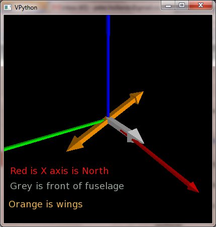
If you meant "The roll axis", then I can see that you entire test, telemetry and question is really about the calibration of your gyros by the acclerometers .... (because they seem to come to rest with a 20 degree roll as in the enclosed picture).

Best wishes, Pete

P.S. I enclose a picture from dcm_viewer in the Tools / Flight_Analyzer directory. I had to patch it to make it work again with your log file. (patch enclosed). dcm_vierwer requires visual python .


--

Guilio_roll_test.jpg
dcm_viewer.py.patch

Giulio Berti

okunmadı,
12 Tem 2012 17:11:1512.07.2012
alıcı uavde...@googlegroups.com
Hi Pete,

You are right, I meant in respect to the ROLL axis...
I Installed visual pyton but I wasn't able to run dcm_viewerer, but inside that file I found a comment:

"## xxx_udb refers to UDB Aviation - Earth, Coordinate System
# east west axis is postive in the west direction."

If you watch my 3D sketch, I chosen the values for XRATE_SIGN &Co to match the aviation convention - airplane. Is this wrong? now I'm gonna changing them to match the udb avion-earth to see if the problem get fixed.

Regards,

Giulio

Giulio Berti

okunmadı,
12 Tem 2012 18:39:2112.07.2012
alıcı uavde...@googlegroups.com
Hi,
now my configuration is:
#define XRATE_SIGN +
#define YRATE_SIGN -  // same as before
#define ZRATE_SIGN +
udb_xrate               gyroMeasureRaw[1];  // same as before
udb_yrate               gyroMeasureRaw[0];  // same as before
udb_zrate               gyroMeasureRaw[2];  // same as before

#define XACCEL_SIGN +
#define YACCEL_SIGN -  // same as before
#define ZACCEL_SIGN +
udb_xaccel             accMeasureRaw[1];  // same as before
udb_yaccel             accMeasureRaw[0];  // same as before
udb_zaccel             accMeasureRaw[2];  // same as before

I did more "roll tests". As you can see from the pictures attached, the feedback correct to half the value of the movement i.e. in a -90 roll movement, after the transient the value is -45, same for the pitch.

So now: is the gyro that outputs a double movement, or is the reference given by the accelerometer which is the half?
Where is calculated the angle given by the accelerometer?
Reasoning a bit, also if the scaling of the accelerometer is wrong, the angle calculated from its components should be the same... so could it be the scale of the gyro ?
I did a test dividing SCALEGYRO by 2, results in  -90 and 90 roll test with half scalegyro.pdf, Amazing, the read value is incredibly stable! but the angle value is the half... I'll do it again recording SUE for Pete.

Are we closer to the solution now?

Huge thanks for the support!

Giulio
-90 to 0 after 0 to -90 pitch test.pdf
0 90 roll test.pdf
0 -90 roll test.pdf
0 to -90 pitch test.pdf
90 0 after 0 90 roll test.pdf
-90 and 90 roll test with half scalegyro.pdf

Giulio Berti

okunmadı,
12 Tem 2012 19:00:0212.07.2012
alıcı uavde...@googlegroups.com
Here is the SUE of a similar test :)

with this setting, keeping the board still, the yaw drifted only of 0.68 deg every minute :O

Regards
roll test1.txt

William Premerlani

okunmadı,
12 Tem 2012 19:16:4812.07.2012
alıcı uavde...@googlegroups.com
Hi Guilio and Peter,

Assuming that Guilo is using Invensense gyros for all three axes with the same sensitivity on all three axes, there is a simple way for him to check whether he has SCALE_GYRO correct:

Run the roll-pitch-yaw demo, with 3 servos connected. After initialization, holding the board level, slowly rotate it 360 degrees around the vertical (yaw) axis. The servo connected to channel 3 will indicate one of the yaw indicating matrix elements. Its initial value is "1.0". As you rotate through 360 degrees, the value will display the cosine of the yaw angle, going from 1 to 0 to -1 to 0 and back to 1.

So, the servo will swing from one end to the other and back, exactly one cycle.

If it does more than that, SCALE_GYRO is too small.

If it does less than that, SCALE_GRYO is too large.

In fact, this is the way that I check to assure that I have the right value for SCALE_GYRO.

Best regards,
Bill


--

Peter Hollands

okunmadı,
13 Tem 2012 03:34:2113.07.2012
alıcı uavde...@googlegroups.com
Guilio,

Nice graphs. Did yo uuse mavgraph ? ( I've not tried that utility yet. )

Back to the main conversation ... we are looking at why the roll on the Madre board, does not return to zero degrees after the board has been rolled to + 90. Instead it seems to return to +45 degrees.

If I was working on your board, I think I would set the gyros to return a zero rate of turn on all axis, by changing a few simple statements in the software.

How about changing the routine read_gyros() as follows ? :
from:-

gplane[0] =   XACCEL_VALUE ;
gplane[1] =   YACCEL_VALUE ;
gplane[2] =   ZACCEL_VALUE ;

to:-

gplane[0] =   0 ;
gplane[1] =   0 ;
gplane[2] =   0 ;

Now the gyros are still, and the only input to the DCM algorithm will be the other variables like the accelerometer and GPS. I have to bear in mind that your GPS code is also new, (NMEA GPS). So ideally, I would ensure that the GPS is not inputting to these tests at this stage. i.e. have no gps reception (put a saucepan over the gps ! or switch off in software)

 Now, the attitude of the DCM is going to be calibrated entirely from the accelerometers. They of course, do their calibration slowly over time, so you must allow 15-30 seconds for them to change the DCM. So I would try rolling by 90 degrees with the gyros set to zero rate, and then watch how well the accelerometers work.

If they work correctly, then you will have halved the problem.

You can then switch back on the gyros, and investigate them further.

Best wishes, Pete


--

Peter Hollands

okunmadı,
13 Tem 2012 03:39:0113.07.2012
alıcı uavde...@googlegroups.com
CORRECTION:

Guilio,

Sorry, I linked to the accelerometer reading code not the gyro code. Here is the correction ...

Previously in rmatc. the read_gyros (corrected link) was:

#else
        omegagyro[0] = XRATE_VALUE ;
        omegagyro[1] = YRATE_VALUE ;
        omegagyro[2] = ZRATE_VALUE ;
#endif

becomes

#else
        omegagyro[0] = 0 ;
        omegagyro[1] = 0 ;
        omegagyro[2] = 0 ;
#endif

Best wishes, Pete

Giulio Berti

okunmadı,
13 Tem 2012 05:07:2913.07.2012
alıcı uavde...@googlegroups.com
G'day Pete, Bill

Nice graphs. Did yo uuse mavgraph ? ( I've not tried that utility yet. ) 
I did everything inside QGroundControl, it's the LogFile plot window (Main->LogFile plot). From that you can export directly in pdf, it's very useful!

we are looking at why the roll on the Madre board, does not return to zero degrees after the board has been rolled to + 90. Instead it seems to return to +45 degrees. 
After a -90 roll, the value goes by itsef to -45 (but the board is still at -90). When I turn the board back to 0, I have a +90 displacement (from -45 to +45) and then the value return to 0 after a while.


If I was working on your board, I think I would set the gyros to return a zero rate of turn on all axis, by changing a few simple statements in the software.

How about changing the routine read_gyros() as follows ? :
from:-

gplane[0] =   XACCEL_VALUE ;
gplane[1] =   YACCEL_VALUE ;
gplane[2] =   ZACCEL_VALUE ;

to:-

gplane[0] =   0 ;
gplane[1] =   0 ;
gplane[2] =   0 ;

Now the gyros are still, and the only input to the DCM algorithm will be the other variables like the accelerometer and GPS. I have to bear in mind that your GPS code is also new, (NMEA GPS). So ideally, I would ensure that the GPS is not inputting to these tests at this stage. i.e. have no gps reception (put a saucepan over the gps ! or switch off in software)

 Now, the attitude of the DCM is going to be calibrated entirely from the accelerometers. They of course, do their calibration slowly over time, so you must allow 15-30 seconds for them to change the DCM. So I would try rolling by 90 degrees with the gyros set to zero rate, and then watch how well the accelerometers work.

If they work correctly, then you will have halved the problem. 

I did a test and no, they are not working correctly. As I fist supposed, the reference from the accelerometer (disabling the gyros) is half the value, both on roll and pitch. but the pitch seems to be reversed.

I'll do also the test suggested by Bill but I think that the correct value for SCALEGYRO is 6.8383/4. (not  6.8383/8 as in the second test of yesterday).

How should I correct the angle seen by the accelerometer?

Thanks

Giulio

Peter Hollands

okunmadı,
13 Tem 2012 06:22:1613.07.2012
alıcı uavde...@googlegroups.com

Guilio

Surely your symptoms can only be explained if X accel is returning different value for gravity from that of Z accel ?

Can you remind us as to whether all 3 accels are on one chip ?

Best wishes Pete

--

Giulio Berti

okunmadı,
13 Tem 2012 07:17:0113.07.2012
alıcı uavde...@googlegroups.com
Pete

I'm using an adxl345 from Flytron, all the 3 axes are in one chip. I used the document attached to calibrate it.
The raw values seems correct (no offset and all with the same scale). I'm feeding the dcm with raw values in a scale of 5280 every G. 

Giulio
Calibrating adxl345.ods

Giulio Berti

okunmadı,
13 Tem 2012 11:04:4513.07.2012
alıcı uavde...@googlegroups.com
We reached a very good point:
disabling the calibration on the accelerometers and feeding the gplane vector with static values while the omegagyro vector is null, the angle was calculated perfectly.
When I used just the values of the accelerometer, keeping its calibration disabled (UDB_XACCEL.offset = 0 ;) the angle was calculated well.
When I re-enable the calibration (UDB_XACCEL.offset = UDB_XACCEL.value ;) the angle seen from it is almost the half and the calibration value and ZACCEL_OFF is -5336 (more or less 1g)
I notice that XRATE_SIGN and YACCEL_SIGN were wrong.
I did this to get things faster (It's boring to wait 5 minutes for a stable measure from the accelerometer):
//#define KPROLLPITCH 256*5
//#define KIROLLPITCH 256
#define KPROLLPITCH 256*50
#define KIROLLPITCH 256*10
I'll revert it when I'll fly.

So now the situation is more clear, we have to understand why the calibration value ZACCEL is so large.. And I have to tune better SCALEGYRO.

Regards,

Giulio

Wouter van Verre

okunmadı,
13 Tem 2012 11:12:4713.07.2012
alıcı uavde...@googlegroups.com
Hi Giulio, 

Your Z accel value should be equal to +/- 1 g (depending on signs etc) because of gravity. You have to account for this when you do your calibration. I dont know how it works in the matrixpilot code, but in my code (which is based on Matrixpilot) I simply add 1g to the value I found in the calibration. So you have to find out what 1g is in your Accel units and then add this value to the calibration value. 

Kind regards,
Wouter van Verre


Date: Fri, 13 Jul 2012 08:04:45 -0700
From: giu...@gmail.com

To: uavde...@googlegroups.com
Subject: Re: Attitude problems

--

Giulio Berti

okunmadı,
13 Tem 2012 19:39:4213.07.2012
alıcı uavde...@googlegroups.com
Hi,
thanks for the Hint! matrixpilot does that here.
My  UDB_ZACCEL.value is very close to 5280, and the gravity is 5280 but this ( ( Z_GRAVITY_SIGN ((int)(2*GRAVITY))) ) term subtracts -5280*2.
I tried to modify it to ( Z_GRAVITY_SIGN ((int)(GRAVITY))) and everything seems to work properly.
Where is the error? why I had to change this?
 
I also changed a bit SCALEGYRO which was 2% too high. Now the attitude tracking is quite good until I rotate the board very fast: in that moment the dcm gains a quite high estimation error (sometimes 45°!) but then it slowly (very slowly, 40-60s) returns to the correct value.

To increase the performance I could probably decrease the accelerometer reading speed while increasing the gyro reading speed.

Probably on Sunday I'll do the first flight test if I'll have enough time :D

Huge thanks again to all for the help!!

Good night,
Giulio

William Premerlani

okunmadı,
13 Tem 2012 20:06:5513.07.2012
alıcı uavde...@googlegroups.com
Giulio,
When you are rotating the board fast, you are probably saturating the gyros at the maximum rate. There is not much you can do about that, reading them more often will not help.
What is the maximum range of your gyros?
In UDB, I started out with 75 degree/second, then went to 300 degree/second, and finally to 500 degree/second, which seems adequate for most aircraft.
Best regards,
Bill

--

Giulio Berti

okunmadı,
14 Tem 2012 03:53:5014.07.2012
alıcı uavde...@googlegroups.com
Bill,
I have a itg3205 gyro (3200deg/s). Anyway I wasn't rotating the board that fast.
As you can see from the picture, I tilted it circularly from 6 to 33s. Using
#define KPROLLPITCH 256*5
#define KIROLLPITCH 256
The time needed to correct the gyro measure is more or less 600s

How can I improve this?

Best regards,
Giulio
rotation test(rotations).pdf
rotation test(settling).pdf
rotation test.csv
rotation test.pdf

William Premerlani

okunmadı,
14 Tem 2012 14:50:2514.07.2012
alıcı uavde...@googlegroups.com
Hi Giulio,

I am sorry, I am really not following you. I suggested doing a yaw test, not a roll-pitch test. The reason for that is the yaw test does not get tangled up with accelerometer issues.

I did not realize that you were using an ITG3205, (which has a digital interface and its own A/D) so all my comments in this thread about gyro gains do not apply, especially my comments about gyro scaling. My comments were based on an analog gyro connected to the A/D converter on the PIC, with a particular A/D setup. So, I am afraid you will have to start from "square one" to determine gyro scale factor.

You mentioned the ITG3200 is a 3200 degree/second gyro. A only glanced at the spec sheet, but I thought it said 2000 degrees/second. In either case, I think the very high range will create several problems, but I will come back to that after you get things working.

By the way, I think you will have to rewrite some of the code in rmat.c that does the rotation update. The implementation there is integer, and the range will not handle much above 1000 degree/second. Above that and there will be integer overflow.

Best regards,
Bill Premerlani


--

William Premerlani

okunmadı,
14 Tem 2012 14:59:1014.07.2012
alıcı uavde...@googlegroups.com
Giulio,

Just to shed some light on a factor of 2 that is used in a few places in the handling of gyro and accelerometer values in MatrixPilot.

MatrixPilot uses 16 bit integers in many places. You have to be careful to avoid overflow.

In particular, the removal of offsets would create overflow if you simply subtracted two sixteen bit values. So, when the rmat routine does the offset removal, it first divides the two values by 2, to produce 15 bit vaues, so the difference cannot overflow. For example:

#define ZACCEL_VALUE ( ZACCEL_SIGN_ORIENTED (( udb_zaccel.value>>1 ) - ( udb_zaccel.offset>>1 ) ))

This means the the downstream values are 1/2 of the scale of the raw values. This why the gravity offset gets multiplied by 2:

UDB_ZACCEL.offset = UDB_ZACCEL.value + ( Z_GRAVITY_SIGN ((int)(2*GRAVITY)))

The reason for the 2 is because GRAVITY is in "downstream" units, and UDB_ZACCEL.offset is in raw units.

Best regards,
Bill Premerlani

--

Giulio Berti

okunmadı,
15 Tem 2012 17:08:5415.07.2012
alıcı uavde...@googlegroups.com
Hi Bill,

I did the yaw test, I rotated completely the board 5 times around the Z axis, I found that every turn the measure was too big of a 2% factor, so I reduced SCALEGYRO accordingly, then I did that roll pitch test for my curiosity.

You are completely right, the ITG3205 is a 2000deg/s gyro (I don't know why I said 3200..) but anyway I really don't need that range my plane is an Easystar...
I bought that gyro because it was on discount and my old analog gyro was broken. Maybe it's better if for the moment I simply limit its output to 500deg/s or so..
What do you think? How should I proceed?

I should change also the scale of the accelerometer, if I understood it correctly, in the first board 1g in "downstream" units is 5280 while in raw units is 2*5280?

Thank you very much,

Giulio
Tümünü yanıtla
Yazarı yanıtla
Yönlendir
0 yeni ileti