Super easy wall adapter mod: 9V plus 170V at 80mA

taylorjpt
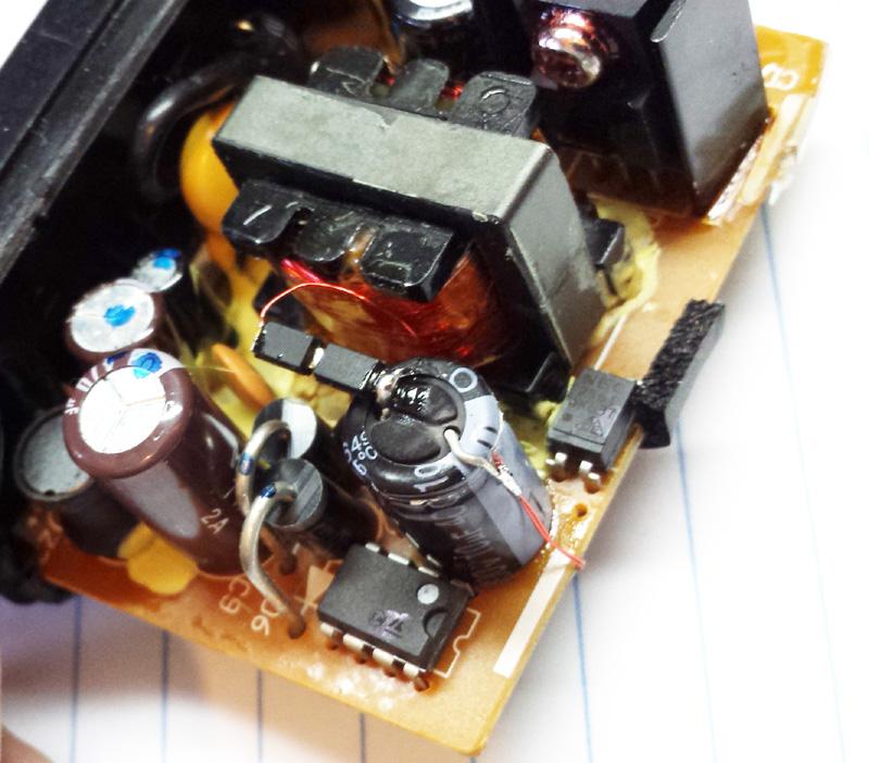
The new winding is 15T #32 to replace the original winding followed by 268T #32 in series with the first winding. The 15T winding goes back into the holes for the old winding and the new fly lead connects to a couple of high speed diodes that feed a high voltage electrolytic cap.
The main output is regulated to 9V with the original feedback circuits and the new winding puts out a voltage that is turns ratio related to the first.
One big advantage is that you don't get the double efficiency hit of an AC-DC feeding a DC-DC boost since all of the power is converted in a single step off the mains. Also, you get the same mains isolation as the original design because you never have to touch the primary... most flyback converters sandwich the secondary between two halves of the primary for better coupling.
jt

gregebert
taylorjpt
Running a long time test: 185V at 75mA plus 9V at 100mA. Diode temperature rise is 8C and ripple on HV is 78mV RMS. Going to let it run til Saturday morning (When I need my bench back).
taylorjpt
Anybody want this unit? On to the next project...
jt

David Forbes
That's a clever hack!
Once thing... you had to saw apart the ultrasonic weld to get it apart,
right? Any good ideas on gluing it back together?
Also, this is not strictly still UL recognized since you modified it,
but it's close enough. Do you consider it to be as safe as the original
unmodified supply?
On 10/13/15 5:35 PM, taylorjpt wrote:
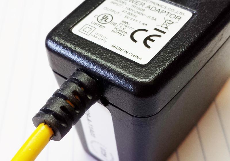
> Just for fun I modified a Cincon TR1509 wall adapter (9V at 1.4A rated) so
> that now it puts out the original 9V plus a regulated 170V at 75mA (13W
> total for both outputs). This requires re-winding the transformer and then
> adding 2 diodes and a capacitor.
>
>
--
David Forbes, Tucson AZ
gregebert
taylorjpt
Once thing... you had to saw apart the ultrasonic weld to get it apart,
right? Any good ideas on gluing it back together?
Never contended that this was still UL recognized after the fact... My statement was simply that the mains isolation was maintained because of the construction of the transformer. For transformers that have split primaries above and below the secondary, I would be reluctant to use them after modification in any case. Where the split primary linear power thread uses transformers outside of their intended application, this modification mantains all of the original creapage distances.
taylorjpt
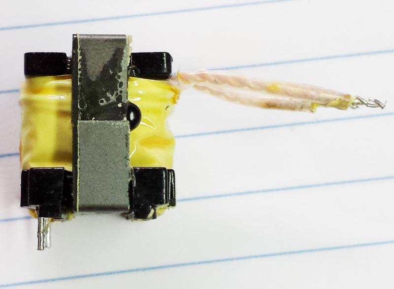
1. Cut the epoxy drops off the outer legs.
2. Heat the cores with a heat gut until the varnish is softened (an exacto knife pokes it easily).
3. Carefully pry the core on the top away from the bobbin.
4. Push out the bottom core with the center post
5. Clean up the excess varnish and polish the legs in preparation for re-assembly.
6. After re-winding the transformer, use a couple of drops of super glue on the outer legs to glue them back together.
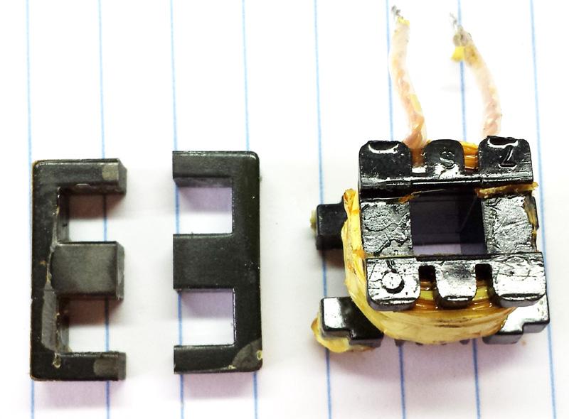
David Forbes
laminations to deal with. They are called E cores because they look like
the letter E.
John said that after he removed the transformer from the board, he
separated the ferrite core halves by heating the glued joints with a Bic
lighter, then pulling the cores out. Then you unwind the tape form the
bobbin and remove the outer winding.
taylorjpt
taylorjpt
This is so much easier than the way I tried to do it years ago by trying to redesign the feedback circuits to make the switcher regulate the high voltage directly: I still needed a low voltage rail to generate the logic bias for the opto-coupled feedback circuits which meant adding a linear post regulator or a separate winding and output rectifier/filter. By allowing the switcher to run at its designed output voltage and putting up with sloppier load regulation I am getting the job done with no board modifications.

John Rehwinkel
- John

Dekatron42

gregebert
taylorjpt
1. The winding area (Not core area) for the secondary of these transformers is designed to support the output POWER for which the power supplies are rated so there is ALWAYS enough winding area, regardless of the voltage that is output. Few thick wire turns for high current == Many thin wire turns for low current.
2. The Cincon TR1509 is a perfect platform for this modification as the secondary is the outermost winding and the cores are glued in a very easy way with regard to separation. The varnish used in the industry has a relatively low transition temperature: I am using a Saike hot air reflow station set to 425F and I heat the core uniformly until the varnish between the core and bobbin yields with gentle pressure. Avoid applying heat to the entire transformer vs just the cores.
3. What ever the power supply is rated for in watts, that is the power that can be delivered before and after the modification. Note that most power supplies have two current limit mechanisms; Primary side and secondary side. Adding a second winding will still use the primary side limits as the current to deliver a particular power output remains constant but since the currents are much lower at higher output voltages for a given power level, any secondary current sensing will never come into play. However, any secondary over voltage protection will still be active since the regulated output voltage has not changed. The 9V output of the Cincon TR1509 is just right as it gives plenty of headroom for a 5V regulator while maintaining a reasonable primary to secondary turns ratio.
It would be possible to feed the high voltage into the feedback network while using the low voltage rail to bias the opto-coupler circuits. This would result in a tightly regulated high voltage output which sloppy low voltage regulation but with sufficient overhead for a 5V regulator the application circuit would not see the variations. Although this goes a bit further than most people are comfortable with, this would have the added benefit of preventing load variation or multiplex scan induced brightness variation in the circuit. I am getting a PWB made that mounts on the HV capacitor to hold the HV diodes and a voltage divider just for this improved scenario.
gregebert

Steven Donaldson
--
You received this message because you are subscribed to the Google Groups "neonixie-l" group.
To unsubscribe from this group and stop receiving emails from it, send an email to neonixie-l+...@googlegroups.com.
To post to this group, send email to neoni...@googlegroups.com.
To view this discussion on the web, visit https://groups.google.com/d/msgid/neonixie-l/6d72ff6d-d737-4316-a26f-f7012f999f70%40googlegroups.com.
For more options, visit https://groups.google.com/d/optout.
taylorjpt
Current sinks are the easiest thing to build so long as you have some reference voltage to start with. The PDF shows a simple saturated cathode drive for well regulated HV and two variations of current sinks (Actually a current sink and current source!) where the first needs to be attached to every cathode and the second can be shared between cathodes in a multi cathode display such as a 1-of-10 nixie. The current sinks have the advantage that they are relatively immune to variations in the high voltage rail as well as variations in cathode conduction voltage.
taylorjpt
taylorjpt
1. No boost converter heating in the target circuit as all the conversion is done in the wall adapter.
2. Super quiet operation, audio and electrical since the switcher operates exactly the same whether it outputs 9V or 170V.
3. Putting the feedback on the high voltage serves as a bleeder current to discharge the output capacitor.
4. Scalable to other voltages: I did a test with another turns ratio and am getting a clean 14W at 300V.
5. Scalable to higher power levels: I did the same mod on a 24W unit and got 140mA at 170V.
6. Failure of the high voltage supply can be fixed by swapping the adapter instead of opening the target circuit.

A. Nonamus
taylorjpt
taylorjpt
How many people would be interested in an AC adapter that puts out 9V and 170V at 15W total? These could also be done in a 9V/300V output version.
jt

Dylan Distasio
I would probably be interested in both, thanks.
--
You received this message because you are subscribed to the Google Groups "neonixie-l" group.
To unsubscribe from this group and stop receiving emails from it, send an email to neonixie-l+...@googlegroups.com.
To post to this group, send email to neoni...@googlegroups.com.
To view this discussion on the web, visit https://groups.google.com/d/msgid/neonixie-l/6aa437e0-28a9-472b-8cb4-3127f4d80d27%40googlegroups.com.

Jon D.
John Rehwinkel
I'd be interested in buying a few. You could maybe even offer a variant with 6.3V for tube heaters and B+ as well. Granted, the tube heater would
probably eat most of your wattage, but for a headphone amp or phono preamp, it would be a nice fit.
- John
taylorjpt
Jt
Dekatron42

Donald Stramock
Sent from my iPad
--
You received this message because you are subscribed to the Google Groups "neonixie-l" group.
To unsubscribe from this group and stop receiving emails from it, send an email to neonixie-l+...@googlegroups.com.
To post to this group, send email to neoni...@googlegroups.com.
To view this discussion on the web, visit https://groups.google.com/d/msgid/neonixie-l/3aa8f2bd-e477-4737-9382-dc39f4ececf7%40googlegroups.com.

GeckospotNixie
taylorjpt
Model 9V 170V
TR1509 15T 250T
TRG1509 11T 184T
The TRG1509 adds a faraday shield to the outside of the transformer but it does not impact the rewinding of the secondary which is the outermost winding in both models.
Dekatron42
Dekatron42
taylorjpt
taylorjpt

croftj
-------- Original message --------
From: taylorjpt <j...@tayloredge.com>
Date: 23/10/2015 6:42 PM (GMT-06:00)
To: neonixie-l <neoni...@googlegroups.com>
Subject: Re: [neonixie-l] Super easy wall adapter mod: 9V plus 170V at 80mA
How many people would be interested in an AC adapter that puts out 9V and 170V at 15W total? These could also be done in a 9V/300V output version.
jt
You received this message because you are subscribed to the Google Groups "neonixie-l" group.
To unsubscribe from this group and stop receiving emails from it, send an email to neonixie-l+...@googlegroups.com.
To post to this group, send email to neoni...@googlegroups.com.

Charles MacDonald
> You may want to make it configurable or be willing to sell them so that
> we can make them what we want. I personally think a 90 - 100v version
> would be sweet!
switcher would handle the inrush current of a Vacuum tube filament but
something that gave enough power to light up a couple of 12AX7 tubes or
something similar with several ma at 170 volts would be quite
interesting for both the audio and Guitar camps.
(12AX7 Draws 12.6 volts at 150ma or 6.3 volts at 300ma.) and likes
anywhere from 100 to 250 volts on it's plate.
--
Charles MacDonald Stittsville Ontario
cm...@zeusprune.ca Just Beyond the Fringe
No Microsoft Products were used in sending this e-mail.
taylorjpt
Since the output voltage is turns ratio dependent, it would be easier to wind them as required for specific output vonfigurations. For adjustability of the HV output, the low voltage output would be variable within a useful range. For instance, for a 100V to 200V output range, the the HV winding is calculated for the highest voltage and then the low voltage winding would be calculated to give the minimum usable voltage for the minimum HV output.
taylorjpt
Every other switcher I've pulled apart splits the primary. The main reason to do this is to limit the leakage inductance: Magnetic field of the primary curcuit that is not part of the secondary curcuit. Leakage inductance shows up as a voltage spike on top of the primary winding added to the turns ratio voltage when the primary transistor turns off, kind of like an ignition coil. You either have to way over rate the transistor or add an energy wasting snubber to keep the transistor from dying.
Dekatron42

Bill van Dijk
Although tempting, you may want to rethink that. Especially in a pre-amp the switching noise may be a problem.
Bill
-----Original Message-----
From: neoni...@googlegroups.com [mailto:neoni...@googlegroups.com] On Behalf Of John Rehwinkel
Sent: Friday, October 23, 2015 9:59 PM
To: neoni...@googlegroups.com
Subject: Re: [neonixie-l] Super easy wall adapter mod: 9V plus 170V at 80mA
You received this message because you are subscribed to the Google Groups "neonixie-l" group.
To unsubscribe from this group and stop receiving emails from it, send an email to neonixie-l+...@googlegroups.com.
To view this discussion on the web, visit https://groups.google.com/d/msgid/neonixie-l/B57A82A7-FB1C-4CDB-9663-98D972C8886D%40mac.com.
---
This email has been checked for viruses by Avast antivirus software.
https://www.avast.com/antivirus
taylorjpt
John Rehwinkel
Since JT is offering to let people try units out, I may be able to test this directly.
- John
taylorjpt
To maintain tight regulation of the HV output I am dividing down the HV to 2.5V and injecting this into the feedback network, where the LV output is used to power the feedback comparator, opto-coupler and any user circuits. The main advantage of this arrangement is that changes in the HV load do not show up as display tube brightness fluctuations (Or punch through in the case of audio amps). An issue that arises however is that by using the high voltage as the feedback source with no preload, when the HV load abruptly goes to zero the switcher will skip cycles until the HV output capacitor is discharged to the regulation threshold resulting in the LV output momentarily collapsing. Once the HV output recovers from the load step, the LV output will stabilize. Although this is not a problem for the switcher itself, any circuit that uses the LV output may brown out during the recovery time.
The test condition for the AC adapter with this circuit is that the LV output maintains sufficient head room for the users LV regulator for an instantaneous step change in HV current from maximum (In this case 170V at 75mA) to zero.
Dekatron42
taylorjpt
Shorting the HV to ground however has the same effect of shorting the LV output to ground: The switcher primary current sense circuit will turn the unit off. These power supplies are designed to handle this type of failure indefinitely.
My choice of a 5 pin keyed connector is with the ground at the center left was made to prevent the HV from accidentally being connected to the LV output even if forced in backwards and give extra isolation from HV to GND.
1 NC
2 LV
3 GND
4 NC
5 HV
Dekatron42
Dekatron42
On Sunday, 1 November 2015 12:09:13 UTC+1, taylorjpt wrote:
Bill van Dijk
1 HV
2 LV
3 GND
4 LV
5 HV
Bill
-----Original Message-----
From: neoni...@googlegroups.com [mailto:neoni...@googlegroups.com] On Behalf Of taylorjpt
Sent: Sunday, November 01, 2015 6:09 AM
To: neonixie-l
Subject: Re: [neonixie-l] Super easy wall adapter mod: 9V plus 170V at 80mA
You received this message because you are subscribed to the Google Groups "neonixie-l" group.
To unsubscribe from this group and stop receiving emails from it, send an email to neonixie-l+...@googlegroups.com.
To post to this group, send an email to neoni...@googlegroups.com.
Dekatron42
taylorjpt
Plot on first page of 0214 PDF is voltage at the end of the new 2 meter cable 3 conductor cable with a 100mA 9V load and 0-82mA 170V load step.
Plot on the second page is the input to the HV rectifier showing the reverse bias stress: As is with the 2 x 600V diodes in series there is 300V of margin at 240VAC input so for 240VAC in, the 800V or 1KV diodes of the same family would result in increased reliability and transient margin. The switching speed of the converter is only 31kHz (32uS period) so that the increase in Trr of the higher voltage devices will not be a problem.
The next step is to back the preload current off to its minimum while maintaining the 9V output cross regulation performance.
Dekatron42
taylorjpt
The forward bias efficiency impact will be minimal for two vs three diodes as the forard voltage at these low currents is so much smaller than the output voltage.
It may even be a wash as the 600V parts are faster and energy is dissipated as the devices switch from on to off during those Trr nano seconds. A faster part is less energy. In either case, it's not worth the energy to calculate it!
Dekatron42
taylorjpt
The probe was connected right at the new HV winding where it enters the rectifier pair.
taylorjpt
taylorjpt
Jt
Jon D.

Greg Jeziorski
Thank You!
Greg

Jon

Jonathan Peakall
Jonathan

Billy Watson
--
You received this message because you are subscribed to the Google Groups "neonixie-l" group.
To unsubscribe from this group and stop receiving emails from it, send an email to neonixie-l+...@googlegroups.com.
To post to this group, send an email to neoni...@googlegroups.com.
To view this discussion on the web, visit https://groups.google.com/d/msgid/neonixie-l/5664B362.1060003%40madlabs.info.

Marcin Adamski
Cheers, Marcin
taylorjpt
Jt

