6M Support

John Williams
Is this undersampling support also valid for TX? Should we now be
considering support for 6M? The PA will support 6M if we redesign the
roofing filter signal path on the PA and the RX filter on the 1.2 and
1.3 frontends.
What happens to the TX reconstruction filter?
John

Alan Hopper
Alan Hopper

Takashi K
Takashi K
Alan Hopper
Takashi K

Steve Haynal
Takashi K
Yes, I needed to disable interporlation. I use the modified 20151018 firmware. In the latest firmware, use initarray_nointerpolation that is replaced the value of Address(0x7) with 8'h20 for Rx LPF off, I think.
I'm not aware of the limitation, thanks. Now my interest about undersampling Tx is whether IMD can be improved or not by using TxDAC. Does anybody have any good ideas (circuits) ?
73, Takashi JI1UDD
Steve Haynal
Takashi K
Steve Haynal
Takashi K
Alan Hopper
Steve Haynal
Takashi K
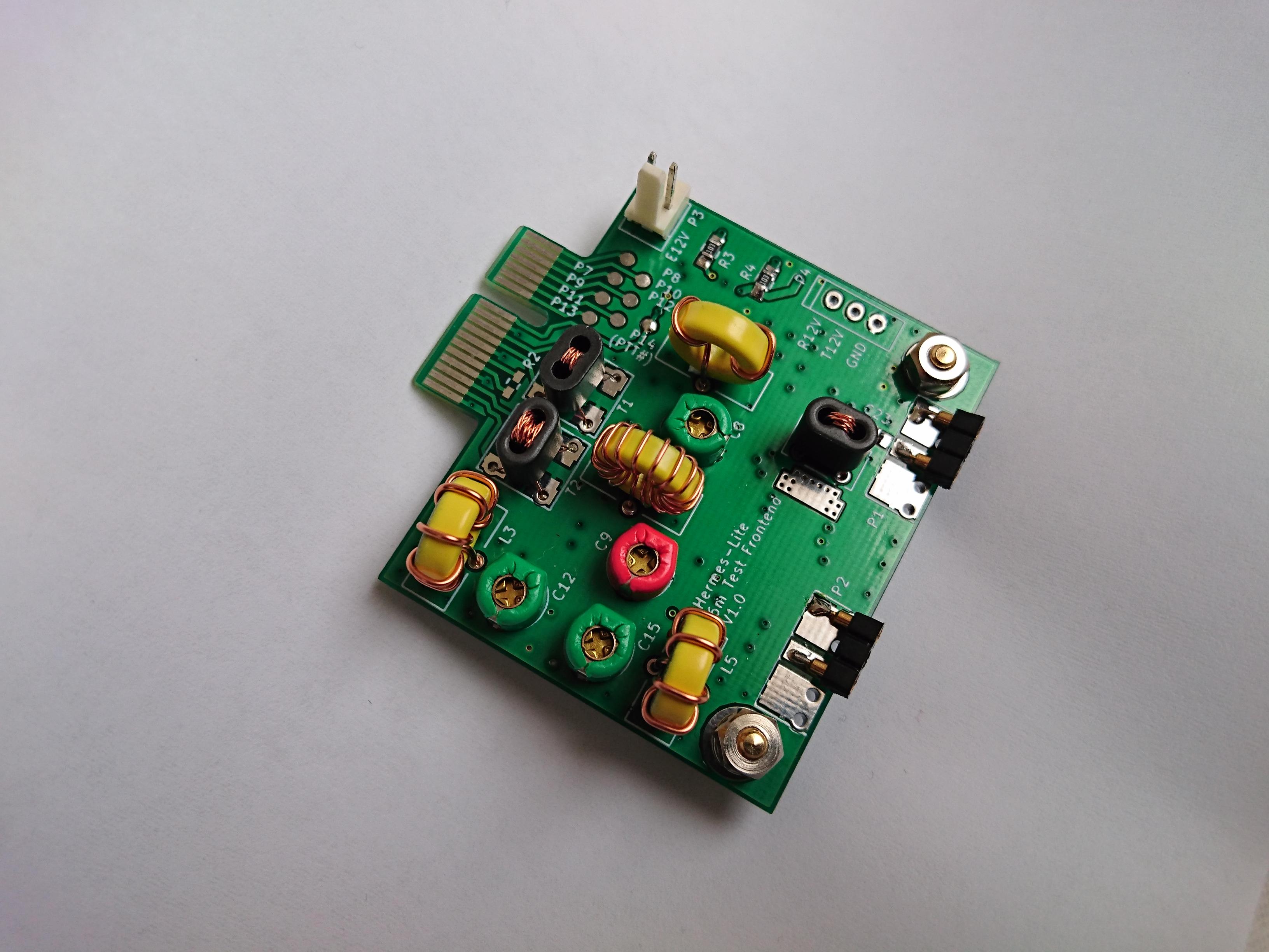
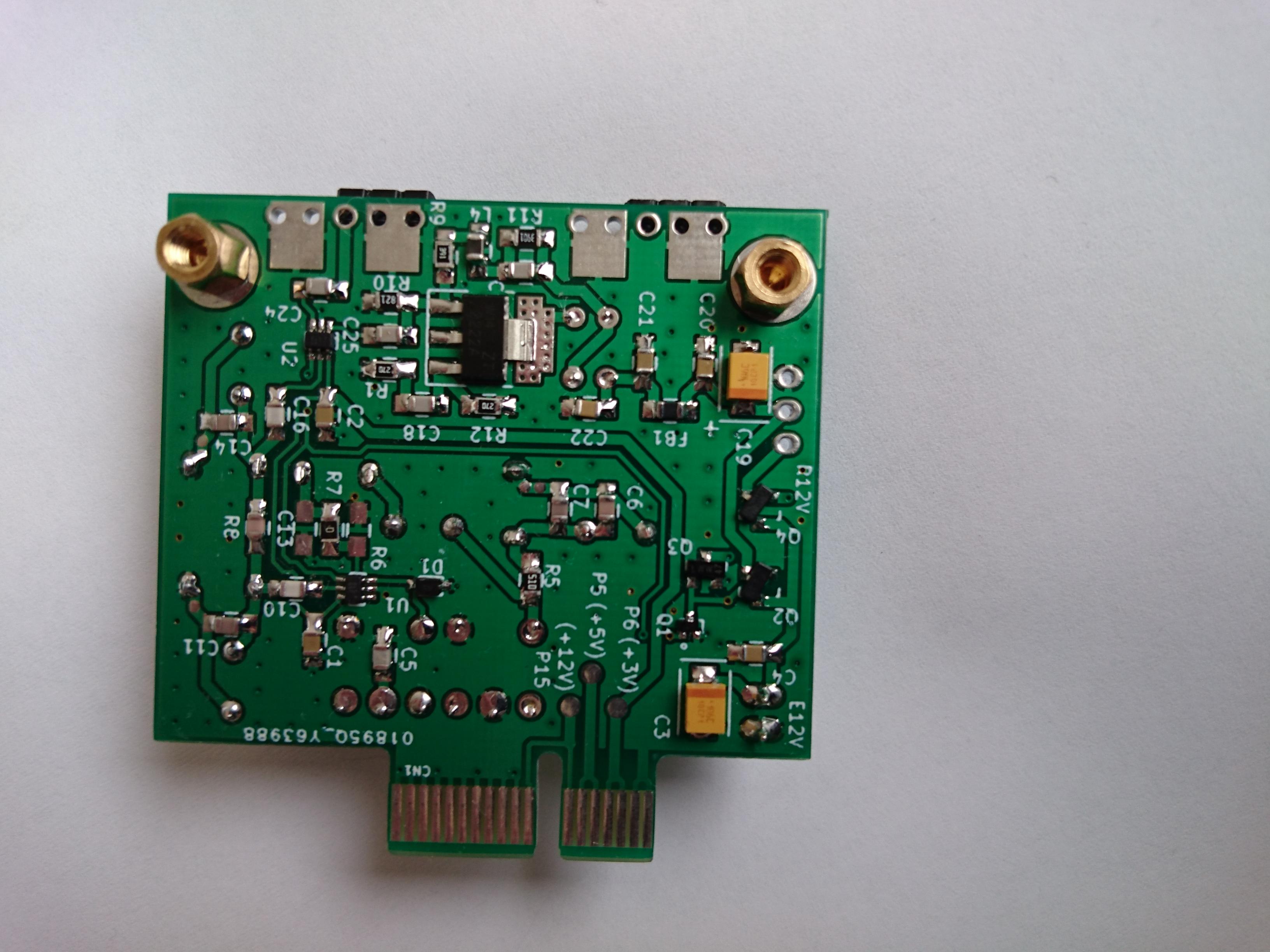
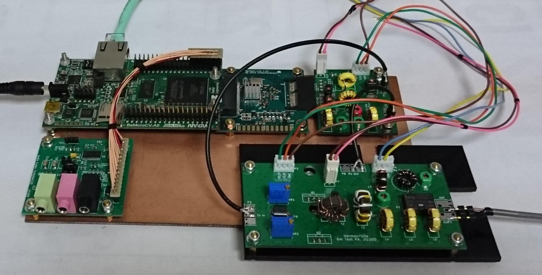
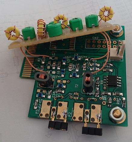
I designed 6m frontend using KiCad, and ordered the board to FusionPCB two weeks ago.
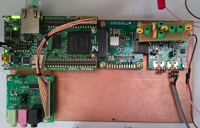
Yesterday, I received it. I assembled immediately.
Now, the first assembled board works well.
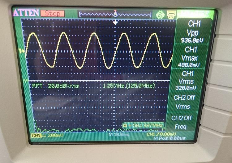
Tx power is about 1dBm, less (-4dB) than my previous experiment.
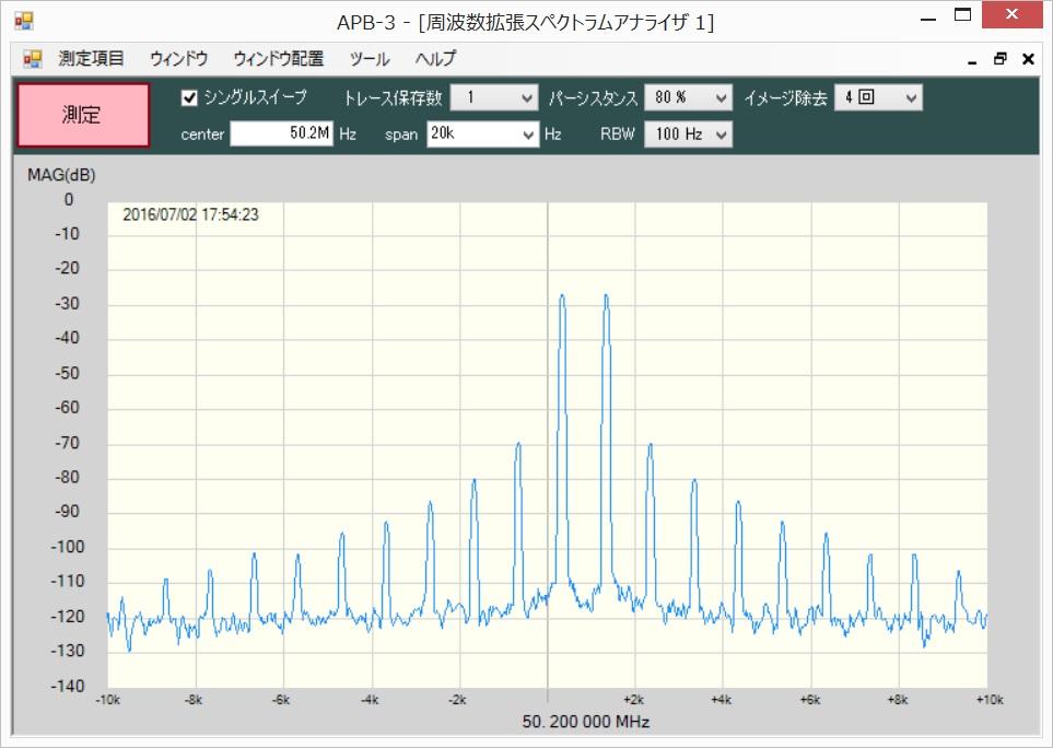
Spurious except harmonics of 50MHz(100MHz, 150MHz,...) seems to be less than 60dBc, including the original 23.528MHz.
Q2 and Q4 are power switch for Tx and Rx circuit. T12V for Tx buffer amp can be supplied from external power circuit.
So, It's not serious.
( My counter measure is, bend the lead of FET reversely and install with rotation. refer to photo)
I attached the schematic v1.1, the bug is fixed.
Steve Haynal
Alan Hopper
Takashi K
Takashi K
Is the 1dBm a typo?
John Williams
Takashi-san,
I happen to have an extra board for one of Claudio's other amps. I am willing to send it to you at my cost if you want to experiment with it. I was going to build it but decided to go in another direction. One other ham on this list built one but I do not recall his name at this time. He made some interesting heat sinks out of 10 or 12ga copper wire.
Here is the link to Claudio's page - http://www.qsl.net/in3otd/ham_radio/PD85004_PP_PA_II/PD85004_PP_PA_II.html
Let me know. It is worth it for me to see how you progress on this undertaking. I have a second Hermes Lite 1.22 that could be re-purposed for a 6M rig.
John - W9JSW
--
You received this message because you are subscribed to the Google Groups "Hermes-Lite" group.
To unsubscribe from this group and stop receiving emails from it, send an email to hermes-lite...@googlegroups.com.
For more options, visit https://groups.google.com/d/optout.

in3otd
FYI, I have recently measured the driver you use in your nice 6 m frontend using a better (but still low-cost) transistor, see http://www.qsl.net/in3otd/ham_radio/driver13/driver13.html#2sc5551a ; it should work a bit better better at 50 MHz than the one using the PZT2222A (it does not need the 680 nH inductor to flatten its gain). By the way, the driver could probably be further improved by tuning it to 50 MHz, the original design was intended to be wideband and cover the HF to 30 MHz only.
73 de Claudio, IN3OTD / DK1CG
Takashi K
Takashi K
Hi Claudio,
The result is, the output decreased about 1dB, so 0dBm now.
Therefore the output power seems to be changed a little even if I use 2SC5551A.
You mean, re-design feedback parameters?
How do you design resistive feed back amplifier always? about Bipolar Tr case and MOS FET case.
John Williams
Takashi-san,
I would very much like one of your boards.
OPA2677 is used in the Hermes design and that design supports 6M
so this should be viable. Perhaps you can take one of the 1.42
boards and modify/remove the filters and give it a try? I will
send you a board.
John
Takashi K
Thank you for your information.
Takashi K
Steve Haynal
Takashi K
Takashi K
Steve Haynal
Takashi K
Steve Haynal
Hi Takashi,
Takashi K
Steve Haynal
Takashi K
So I will try your suggestion. Also I will check the difference ad9866_drive_level setting between your new FW and Claudio's.
Steve Haynal
Takashi K
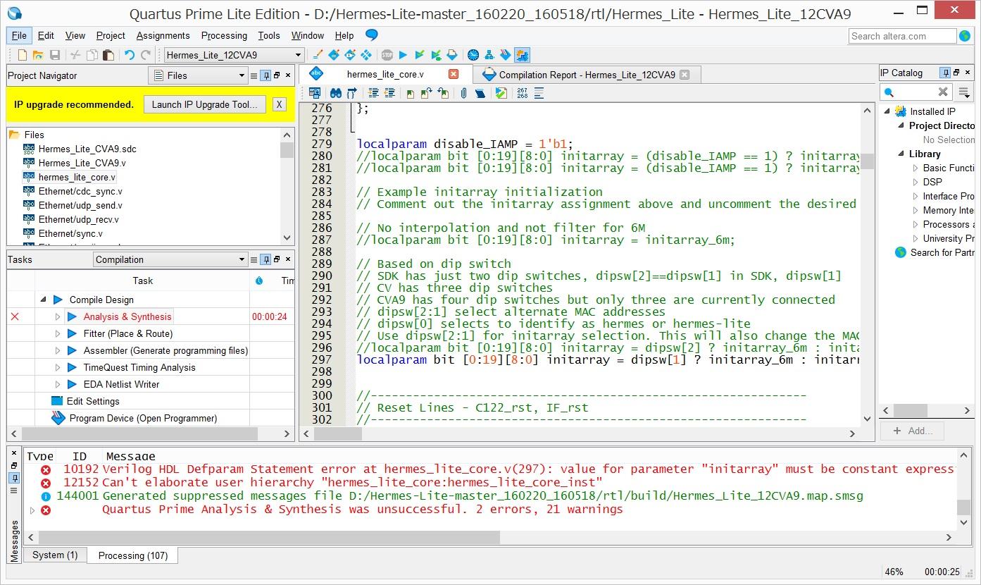
Takashi K
So I use dipsw[1] in hermes_lite_core.v instead.
Steve Haynal
Takashi K
Takashi K
John Williams
Takashi-san,
Perhaps I am confused - is R12 and R13 truly DNI? On my single stage amplifier using the RD16HHF1 instead of the RD06HHF1, I use a 270 ohm R in that position. Also, I use a 100nH inductor instead of the 2.2 ohm gate resistor. We just measured the amp and it is stable well past the 50MHz band.
John - W9JSW

Joe
Takashi K
John Williams
Takashi-san,
How much gain are you achieving? Attached is my design, but I
have not yet tested it. However it is derived from the PA-2008
design that is also attached. They both use 150pf mica cap on the
output transformer.
John
Takashi K
Takashi K
John Williams
Takashi-san,
We are seeing around 20db gain on the single mosfet design. I
expect a few more DB on the PP one but have not tested it yet. The
reason we were considering it was to have less harmonics.
On your amp, why not add a norton preamp stage to gain 8-10db? We
did that on the 1.0 version of my PA when we were seeing 10dbm
output on earlier versions of the frontend. I think Claudio's page
shows some data and would indicate if it can run at 54MHz.
Our current plan uses opa2677 and get a solid 20dbm, thus the 1.1
PA no longer has the norton preamp. Perhaps you should consider
that as well. It can provide differential output and simplify the
input circutry of your PA. The design is from hermes, that
supported 6M band.
John
Takashi K
> I expect a few more DB on the PP one but have not tested it yet.
> The reason we were considering it was to have less harmonics.
> We did that on the 1.0 version of my PA when we were seeing 10dbm output on earlier versions of the frontend.
> I think Claudio's page shows some data and would indicate if it can run at 54MHz.
They didn't get 1 watt output power in my test condition (frontend 6m drives them), needs final amp or driver amp.
I considered that which is better IMD totally, two stages amp? or one stage amp?
And I chose one stage amp. That's the reason.
I need to study how to improve IMD around output transformer at first.
When using input transformer without center tap,
Just my experience. please check it if you have a chance.
It's extremely good characteristics. IMD doesn't get worse at all in my test.
But It is expensive and has high power consumption(= hot).
See SV1AFN homepage.
Takashi K
If apply this firmware,
in3otd
you can find all the theory about the compensation of the transformers response using some parallel capacitance in the old Philips Application Notes
http://www.radio-kits.co.uk/radio-related/Linear_PA/ECO6907.pdf
and in particular
http://www.radio-kits.co.uk/radio-related/Linear_PA/ECO7213.pdf
but I'll say that in practice you just determine the best value experimentally, hi.
73 de Claudio, IN3OTD / DK1CG
On Sunday, June 26, 2016 at 11:04:32 PM UTC+2, Takashi K wrote:
[snip]
in3otd
in theory you should be able to get about 4 W CW from that amp and a figure of 4 W PEP (which are really 2 W read on a power meter, 1 W per tone) in SSB sounds reasonable. The 1 W you get in SSB is "per tone" or the total output power?
Feedback could improve a little the IMD3, but you'll have less gain... Is the PA intended to cover also the HF or only the 6 m band?
73 de Claudio, IN3OTD / DK1CG
Takashi K
Takashi K
John Williams
It would be good to try the 1.42 board at 6M with appropriate Tx
differential filter for that band. Perhaps Jim Ahlstrom can
refresh our memory on what spurs occur between 10M and 6M that are
problematic? If we allow a spur in that space on a 1.42 frontend
that has a 6M filter, perhaps the PA TX LPF filter can remove it
for 10M and lower freq's. I am not proposing that we change the
160M to 10M design point per se, but wondering if there are
alternate build options for those that desire to operate on 6m?
Takashi K
John Williams
I believe so, or one can have two build options on one board.
Build for 160M to 10M or build for 6M.
Steve Haynal
Takashi K
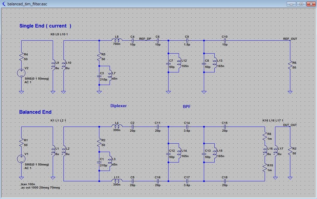
But, In both cases the important point is whether we can design good Tx differential BPF for 6m or not.
As 6m signal is image signal and less than fundamental signal, I think we need high Q circuit and to care VSWR at TxDAC output.
Takashi K
Thank you for your information. I will try to use Elsie later.
For Rx PreAmp, when I used my frontend 6m with PowerSDR to hear some QSOs, I felt the sensitivity was lower than my ICOM IC-703.
Dither: ON
Random: ON
Attenuator: Enable, value: 0
S-ATT : 0
AGC : Med
AGC Gain: 90-100
Takashi K

James Ahlstrom
It would be good to try the 1.42 board at 6M with appropriate Tx differential filter for that band. Perhaps Jim Ahlstrom can refresh our memory on what spurs occur between 10M and 6M that are problematic?
John Williams
Takashi-san,
The Power 2 board implements 2 hermes features. VFWD which is
sensing of the opa2674 output, max of 500mW. The FWD/REV lines are
for remote sensing. In my implementation, I sense the output of my
50W hardrock type amp (actually a ARRLHBC Run 2 amp). The circuit
was derived from a K3 sensing design. I chose it because the
inductors are trivial to wind. You can see both of these (in
earlier configurations) on my qrz.com page. It also derives 5V
and 3.3V for my HL 1.22 board.
To use the boards, if you do not enable Alex support in PowerSDR, it senses VFWD. If you enable Alex, you see Fwd/Rev function, depending on the setting of the meter pulldown. On the PA tab, you can expose some more data fields and actually see forward reverse and vfwd all on one screen. Very handy.
They also have opto-isolated signals for CW in, CW out and PTT
in.
John
Steve Haynal
Takashi K
I understood that VFWD can be monitored on PowerSDR and currently you use the sensing circuit derived from K3.
Takashi K
Takashi K
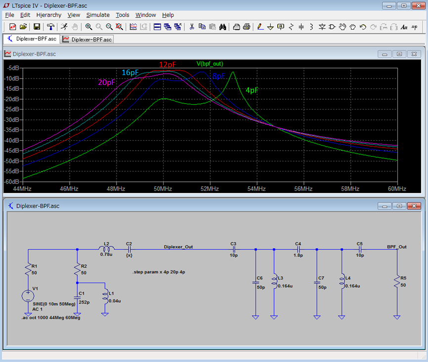
I have simulated and compared each other by using LT-Spice.
Takashi K
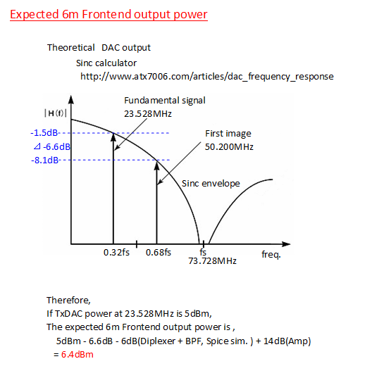
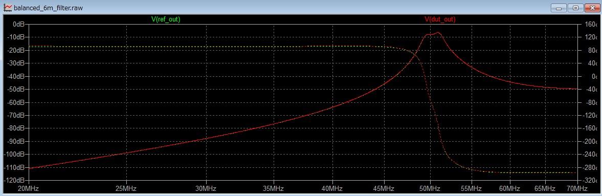
The result is,