Assessing the need for front-end bandpass filters

irbsu...@yahoo.co.uk
I now have a selection of bandpass filters including a nice Dunestar set (now I have fixed it!), and would like to carry out some on-air tests to help determine what difference bandpass filters will make to the receiver.
Here in the south of the UK I have very strong local MW transmitters that are a real test of IP2 performance with IMD products falling in the 160m amateur band.
What I would like to do is make a note of the ADC dBFS level with and without various filters. This will help define the number and specs.
If I could extract wideband adc data I could do it mathematically but it would be better to actually do a live test.
So my question is: do we have any software that can display the ADC dBFS level accurately?
Could QUISK or Spark be easily modified?
Thanks,
Andrew
G4XZL

Alan Hopper

in3otd
I had in mind to do something similar, recording the noise floor every second or so with and without a bandpass filter switched in, should not be too difficult to have all this automated and record the noise floor over the day to see if and when the bandpass filter makes a difference. I thought that in general the IMD will appear as an increased noise floor, if caused by several strong signals over a large bandwidth.
Quisk currently does not handle the wideband ADC data, I did a quick hack to extract and show them on the time-domain scope some time ago but we should probably convince Jim to add the proper code to Quisk, hi.
Alan, I saw that the ADC DC offset can change a lot between gain steps, IMHO if you show the ADC "dBFS" reading this should include also the DC offset, otherwise if you remove it from the data one could wonder why the ADC clips at less than the maximum code.
73 de Claudio, IN3OTD / DK1CG
Alan Hopper
Alan Hopper

James Ahlstrom
On Wednesday, June 21, 2017 at 5:18:07 PM UTC-4, irbsu...@yahoo.co.uk wrote:
What I would like to do is make a note of the ADC dBFS level with and without various filters. This will help define the number and specs.
in3otd
or even 20log(max(abs(adc)/2048))
yep, this is what I think gives the right "dBFS" reading. As you said, this would be an "ADC level meter" not an "input signal level meter", due to the DC offset.

Graeme Jury
73, Graeme zl2apv
irbsu...@yahoo.co.uk
Regarding the dc offset - yes it must be included, I would have thought that the effect would be small compared to full scale, do you have an idea of the difference it will make by including it?
Basically what I am trying to do here is get a metric on the highest LNA gain that can be tolerated before ADC clipping with and without various filters. I'm not specifically looking at IP2 although we know the receiver is not particularly good in that respect. I only mentioned it really as a comment about the strong local broadcast and what it does to poor receivers, or actually even good receivers!
Having the dBFS value allows other measurements like rising of noise floor to be referenced back also.
HDSDR has one now and I find it quite useful.
Graeme, thanks for the link, very interesting, here too if you had a dBFS value would have been useful as it would give you a figure for the improvement the filter gives.
One last comment, I do realise that every QTH will be different depending on antenna and local transmitters but I still think the information would be useful guide for people, and perhaps others could do similar tests.
Andrew
G4XZL
G4XZL
Alan Hopper
irbsu...@yahoo.co.uk
I have tried the new version with my Hermes-lite and works very well, I like the dBFS display, its response time is a little long though, could it be sped up a bit?
Steve is obviously doing some clipping calculations in the FPGA which outputs to the string of leds, maybe that could be accessed?
By the way it doesn't work very well with my Hermes board, is this expected?
Thanks,
Andrew
G4XZL

Steve Haynal
Alan Hopper
in3otd
Hello,
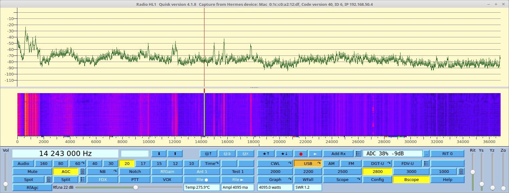
I've added an external BPF which can be switched in and out
via USB and recorded the RX signals levels in the 20 m band with and
without it over a few hours; the idea was that the strong signals from the
broadcasting stations in the 41 m band could cause some second-order
intermodulation at 14 MHz. The antenna here is a good ol' 14AVQ trap
vertical in a noisy urban environment.
The filter passband goes from
about 12 MHz to 17 MHz and the 41 m band is attenuated by more than 30
dB; the losses in the passband are very small, about 0.3 dB or so. The
filter was switched by two mechanical relays to avoid adding any
intermodulation and also because using the PE4259 would have needed
doing another PCB, prototyping dead-bug style with SC-70 components is
no fun, hi.
A python script extracted the min, median and max values from every 48 kHz spectrum centered around 14.2 MHz computed by the Quisk routines, averaged these values over 30 seconds, saved them to a file then switched the BPF and started over again.
I was quite convinced that some of the noise floor was caused by the IM2 but this does not actually seems to be the case:

the difference in the levels with and without the BPF is quite constant at around 0.5 dB, especially for the min and median values; there is some more variation in the max values but this is likely due to the signals levels variation in the 30 second periods.
The relays USB control interface got stuck in the early morning for some reason, so I had to restart the capture and I'll try to do a recording over a whole day.
Note that there are some periodic increases in the noise floor here, didn't notice this before and I don't know where that comes from.
73 de Claudio, IN3OTD / DK1CG
James Ahlstrom
irbsu...@yahoo.co.uk
Great on the meter, fantastic about displaying the wideband data!! Don't like to push my luck, but any chance of a waterfall too:)
Thanks,
Andrew
G4XZL
irbsu...@yahoo.co.uk
Great work!
I am dubious also that IM2 would raise the noise floor these days anyway. Some years ago there were many suggestions that noise floor raising due to IP3 was happening. I'm not convinced its a problem these days.
Even if many stations are causing IMD that resembles noise, its probably below the many other noise sources we have to deal with these days. Maybe you would notice it if you are in the countryside with low noise levels and a big antenna. A switched attenuator would easily reveal if it is IMD.
Your script would be really useful for general noise monitoring as you have already found. Is it something that can be easily run?
Andrew
G4XZL
Steve Haynal
Steve Haynal
James Ahlstrom
in3otd
Hello Steve,
I tried to run the spectrum measurements for a longer
time but got some issues with one of the relays, that started to show
high losses in the "normally closed" position. Its behavior was quite
strange, just after switching it showed a loss greater than 10 dB then,
over a few seconds, it recovered to the usual practically zero losses.
Had to add some "wetting current", a few mA immediately restored the
normal functionality - maybe those surplus RF relays had switched
thousands of times already and needed come cleaning, hi.
I'm wondering if we should do this too with the relay on the H-Lv2b3? It's a completely different relay but likely not immune to this kind of problems.
Here is an updated noise floor graph, covering a whole day:

not much difference w.r.t. the previous one, maybe between midnight and 6:00 AM a slightly higher difference between with and without filter can be seen but not that much really.
So, based on these measurements, a BPF seems not really necessary on 20 m here... For the other bands some more measurements would be needed to draw some conclusions, which would be of course valid only for my QTH and current antenna, but I start wondering if we could have just a couple of HPF to cut the broadcast stations in the lower HF.
I can surely increase the gain significantly before clipping when using the bandpass filter, right now (11:00 pm local time) I can go until 18 dB without BPF and until 37 dB with the BPF (at 14.2 MHz, with the BPF described above). BTW, I'm using 10 dB of gain for the measurements above, IIRC that is more than enough to bring the external noise quite above the H-L noise floor.
73 de Claudio, IN3OTD / DK1CG
Alan Hopper
James Ahlstrom
On Monday, June 26, 2017 at 5:05:12 PM UTC-4, in3otd wrote:
I can surely increase the gain significantly before clipping when using the bandpass filter, right now (11:00 pm local time) I can go until 18 dB without BPF and until 37 dB with the BPF
James Ahlstrom

Jack Generaux
James Ahlstrom
in3otd
also here with my H-Lv2b2 the bandscope is not showing anything. It could be that the data are not properly sent by the H-Lv2, I tried to dump the EP4 data as received and they are all zero. Due to this I also get an error
Traceback (most recent call last):
File "/usr/lib64/python2.7/site-packages/wx-2.8-gtk2-unicode/wx/_core.py", line 14665, in <lambda>
lambda event: event.callable(*event.args, **event.kw) )
File "quisk.py", line 5199, in OnReadSound
self.smeter.SetLabel(" ADC %.0f%% %.0fdB" % (d / 20.48, 20 * math.log10(d / 2048)))
ValueError: math domain error
73 de Claudio, IN3OTD / DK1CG

Dani EA4GPZ
I'm running Quisk 4.1.8 with the latest HL2 firmware. This firmware has
the newer protocol for the HL2, which includes a different way to set
LNA gain. Quisk has to be patched as below.
The bandscope doesn't work (nothing displayed in the spectrum or
waterfall). The following traceback occurs continuously when bandscope
is selected:
Traceback (most recent call last):
line 16762, in <lambda>
math.log10(d / 2048)))
ValueError: math domain error
the wideband data with gr-hermeslite2 (with the HL2 and older firmware),
and it worked well. I've just checked and it doesn't work now, perhaps
because of changes in the new firmware.
I'll try to look at this more carefully in the next few days.
73,
Dani.
------------------------
diff -ur a/hermes/quisk_hardware.py b/hermes/quisk_hardware.py
--- a/hermes/quisk_hardware.py 2017-06-06 19:33:11.000000000 +0200
+++ b/hermes/quisk_hardware.py 2017-06-30 22:35:24.027703667 +0200
@@ -244,13 +244,7 @@
QS.pc_to_hermes(self.pc2hermes)
if DEBUG: print ("Change AGC to", value)
def ChangeLNA(self, value):
- # value is -12 to +48
- if value < 20:
- self.pc2hermes[2] |= 0x08 # C0 index == 0, C3[3]: LNA +32 dB
disable == 1
- value = 19 - value
- else:
- self.pc2hermes[2] &= ~0x08 # C0 index == 0, C3[3]: LNA +32 dB
enable == 0
- value = 51 - value
+ value = ((value + 12) & 0x3f) | 0x40
self.pc2hermes[4 * 10 + 3] = value # C0 index == 0x1010, C4[4:0]
LNA 0-32 dB gain
QS.pc_to_hermes(self.pc2hermes)
if DEBUG: print ("Change LNA to", value)
irbsu...@yahoo.co.uk
Appears to be working on my H-L v1 with the original clock at 61.44MHz, but the bandscope starts at 1.5MHz not 0MHz?? Is there a way to adjust this please?
(does not quite work correctly with real Hermes, I get a display but the dBFS meter is not correct, presumably that's due to it being 16 bit?)
Thanks,
Andrew
G4XZL
Steve Haynal
James Ahlstrom
On Friday, June 30, 2017 at 7:51:01 PM UTC-4, Steve Haynal wrote:
but will try to debug this on Monday or Tuesday.
James Ahlstrom
Graeme Jury
This is such a useful addition to quisk and is an excellent tool to evaluate what filters are needed. You may be interested to know that the spectrum in New Zealand is very similar to that shown in your bandsccope attachment except that the absolute levels were higher in the first 3 MHz. It appears that in ZL it is not necessary to have a high pass filter after the 30/20 M one although in my test bed I will continue to add the 17/15/12/10 M HPF as originally planned if I can fit it on the 100x100 board as it may be useful in transverter service or as an experimental tool. It would be useful to capture the bandscope at intervals to get a picture of signal levels over a 24 hour period and of course when there is a band opening although that is near impossible in the present state of the sunspot cycle. My observations on the upper HPF not being so valuable may not apply at the peak of the cycle.
Jim I hate to call on your time but it would be a great feature for HiQSDR please. I use this radio as my main rig and test bed but having said that I feel the Hermes-Lite will occupy an equal place as it matures.
73, Graeme zl2apv
Dani EA4GPZ
> However, this may not be completely Quisk's fault. I have used before
> the wideband data with gr-hermeslite2 (with the HL2 and older firmware),
> and it worked well. I've just checked and it doesn't work now, perhaps
> because of changes in the new firmware.
>
> I'll try to look at this more carefully in the next few days.
I've just been looking into the issue with the HL2 wideband data.
Firmware 20170226 works fine with Quisk.
Firmwares 20170228 though 20170510 only send zeros as wideband data.
This produces the problems I was experiencing with Quisk and gr-hermeslite2.
I don't know what were the changes between 20170226 and 20170228, but it
seems that they introduced a bug which broke wideband data.
73,
Dani.
in3otd
if I read the H-Lv2 git repository history correctly, the only change between these two releases was this commit. There were quite a few changes in hermeslite.v but I don't understand the code well enough to see where the problem is.
73 de Claudio, IN3OTD / DK1CG
James Ahlstrom
On Saturday, July 1, 2017 at 12:45:21 AM UTC-4, Graeme Jury wrote:
Jim I hate to call on your time but it would be a great feature for HiQSDR please. I use this radio as my main rig and test bed but having said that I feel the Hermes-Lite will occupy an equal place as it matures.
irbsu...@yahoo.co.uk
My bandscope starts at 1.5MHz, it doesn't start at zero like your plot.
Is there a trick I'm missing??
Thanks,
Andrew
G4XZL
James Ahlstrom
irbsu...@yahoo.co.uk
Its 61.44MHz.
Andrew
G4XZL
James Ahlstrom
irbsu...@yahoo.co.uk
Here's a screenshot. It shows my off-air spectrum received via my antenna plus a 5MHz signal from my signal generator at a level of -30dBm coupled in with a combiner. Also noticed the top frequency is limited to ~29MHz.
Could it be something in my config file?
Loads of interference at my QTH due to broadband and PLT as you can see between 10 and 25MHz.
Andrew
G4XZL
James Ahlstrom
irbsu...@yahoo.co.uk
That's it! I had it set to 0.9 because I don't like seeing the roll-off you normally see.
Maybe for the Bandscope this could be automatically switched to 1.0 then switched back to whatever the user has selected before?
Working well, shame there can't be more resolution, maybe in the new protocol?
Thanks,
Andrew
G4XZL
pic attached, mediumwave broadcast can now be seen!
James Ahlstrom
On Saturday, July 15, 2017 at 5:05:44 PM UTC-4, irbsu...@yahoo.co.uk wrote:
Maybe for the Bandscope this could be automatically switched to 1.0 then switched back to whatever the user has selected before?
James Ahlstrom
Graeme Jury
I am following your project with great interest and your results are in line with what I would have expected from my own experiments. Unfortunately I can't provide the exact numbers at present due to having partially dismantling my unit pending a partial rebuild. I used a 1.7 MHz HP filter permanently in circuit and then HP filters for 80, 40, 30/20. 17/15. I would agree with your findings that the filters above 80M don't help a lot but I can see a little improvement with the 40M on 40M vs the 80M one on 40M one but can't at present tell you by how many dB. My filter system looks good on the quiskVNA with the broadcast band being down by 80 dB and 1.7 to 3.4 MHz being down 40 dB with the 80M HP filter switched in. I guess you are going to have an LP filter set for TX set up to cover 2 bands where appropriate like 30/20 etc.
I am wondering if you are making plans to to be able to operate on say 30M but skim from maybe 80M to 15M. This is going to mean having the 80M HP filter (always in circuit in your case) and 15M LP filter in circuit while on receive for the skimming receiver but when you go to transmit you will need to switch in the 30/20M LP filter and then restore the previous configuration when back on receive. Maybe to keep things simple you don't intend to support skimming or other wideband operation. I know that I am getting very complex with my own filter set but it is meant to be a general purpose set which has the dimensions and inputs to match Hermes-Lite.
I don't know if you have looked at this yet but I also got a very worthwhile improvement from having a roofing filter on RX. Currently it is a 6M one but for the HL a 30 MHz filter would have been even better. The breakthrough from FM broadcasting is possibly an alias issue rather than filter breakthrough but anyway the filter eliminated it.
73, Graeme zl2apv
Steve Haynal
James Ahlstrom
Graeme Jury
Like yourself Jim I am learning hugely from this discussion and also from the work that John W9JSW and Glenn VK3PE have done. I have attached a picture of my PCB to date which has a full Tx and Rx set of filters which look likely to be able to fit on the 100mm x 100mm PCB but there are still more components to go. I think you will have little problems Steve with relay capacitance affecting the filter values and just a small amount of tweaking on the higher frequency filters will be needed. In my own case with the diode switches there is a magnitude more capacity and I was able to cope with that on my test board but of course the final higher density PCB may be another story.
Regarding the roofing and floor filters. Yes I did take into account that the HL has the 30 MHz LP filter on board (and it works brilliantly with my huge FM signals) but due to the configuration of my TX and RX filter switching it was easier to just leave it in on RX. I am paying an 0.3 dB penalty for this and it has little effect on RX as the noise goes down with this too. On TX the total filter loss (Band cascaded with Roofing) is 1.2 dB and at least 50% of this is diode switching loss and the chokes feeding the switching current to them. I am still working on better chokes and may gain a bit there.
My out of band isolation is around 42 dB going down to 58 dB at 40M band or lower. I expect with relays it would be a lot better and I recall measuring the QRP Labs filters and getting a pleasant surprise but I forget where I posted the result. I have provided a bypass for the filters which is 0.6 dB on Rx and 0.3 dB on Tx which again is inferior to what relays could provide. I am not sure what the physical size of your relays are Jim but the HK-4100 relays John Williams used were small and cheap but not as small as the relays in the QRP Labs filters..
With the skimming I intended to have extra buttons to provide a skim 1, 2, 3 etc. output or any other GPIO functions and let the smart filter board make the filter decision on transmit based on the band selected. John Melton already provides output to GPIO pins on the RaspberryPi so my writing in some buttons as a widget on Quisk would not deviate too much.
73, Graeme zl2apv

Takashi K
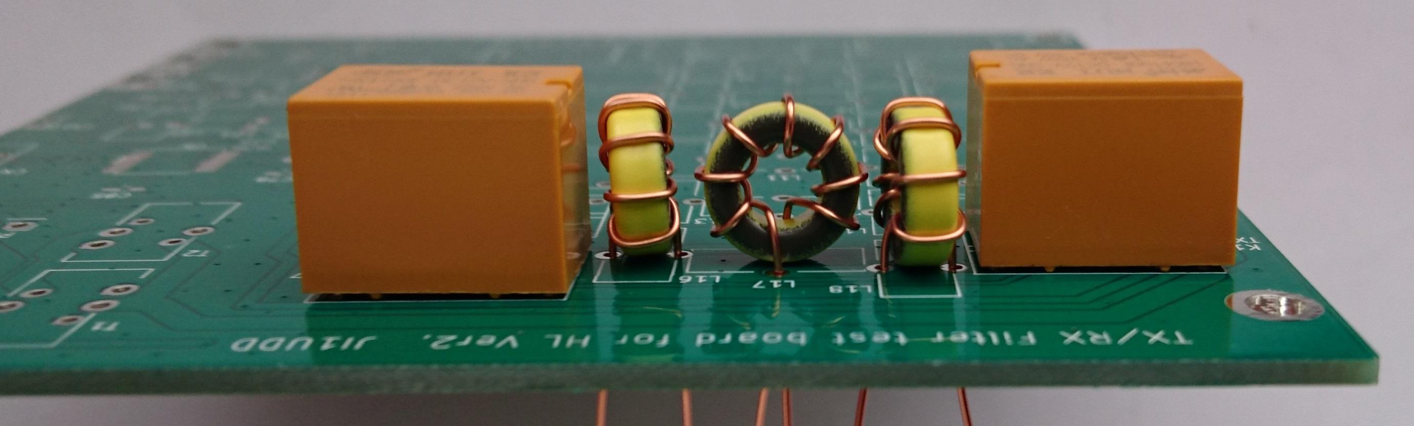
I attached the schematic and photos. The circuit configuration is based on the Pre-V2 amplifier's LPF, John's FR-Sense board and Graeme designed HPF circuit.
I have not assembled and tested it yet. But It should be able to directly connect with HLv2 by pin-header and pin-socket. I chose toroidal coil for LPF in order to minimize filter loss because I want to make a standalone tranceiver without post linear amplifier. As toroidal coils need around 10mm height, I decided to use the same chinese cheap relay that is on hand as Pre-V2 amp instead of diode switch. I'm thinking two MCP23008 are used for Tx and Rx filter switch and chose TPL7407 as a relay driver because it is inexpensive and has small package; TSSOP-16.
The optional tsv filter circuit is for 2m or 6m transverter interface but I don't have the detail plan now. I'm thinking vaguely that it can be realized by low power output from RF1 and local frequency from CL2.

f6itu
Hi group
FYI
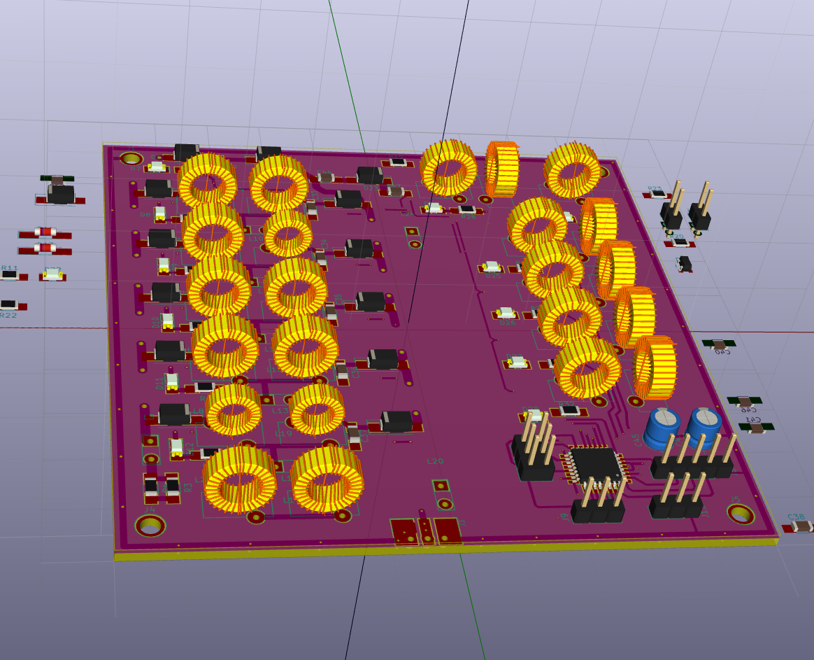
I used Taka’s same 10x10cm format but with a different approach
- Absolutely NO “on board” logic, to accommodate any kind of switching command set : original J16 Hermes SPI protocol, I2C, bcd, decimal etc. Decoding will be located on another board to remain compatible with any kind of rig control
- Separate lpf and hpf board to fit any RF power in the TX / lpf path (50 W or 100W max ? not yet decided. So far, everything has been sized for a 20 W amp). Each filter, lpf and hpf, are located on different boards using same dimensions. Theses boards are mounted “piggy back way” to offer minimal crossband coupling
- T50 Toroids at least and 2 amps relays are used to limit losses on higher bands
In other words, a kind of Alexiares-like filter with a set of different control board to accommodate any kind of transceiver or any future evolution of the H.L.
I’ve not yet decided what kind of topology to use. So far, the M derived gives me the best impedance and phase and a nice frequency rejection on F2 and F3, but less overall rejection compared to a classical elliptic filter.
It’s a heavier and space consuming approach compared to an H.L. dedicated filter. But it’s the simplest way to stay compatible with the whole “hermes” family (H.L., Red Pitaya, Hermes/Angelia/Orion mk1..) or any other SDR, even an old "softrock/mobo" combination


the first "3D" brd is the lpf, the next is a simple hermes SPI decoder handling all the filter/antenna TX/RX and swr security switching.
I hope the final design will be tested before end of August.
73' Marc f6itu

John Williams
Taka-san,
Well done! I was thinking of using some of my prior work as a
basis for a similar layout. Alas, I have been too busy lately to
do much more than follow the progress of this filter work. This
looks excellent!
I will be anxious to see how this performs operationally.
John W9JSW
--
You received this message because you are subscribed to the Google Groups "Hermes-Lite" group.
To unsubscribe from this group and stop receiving emails from it, send an email to hermes-lite...@googlegroups.com.
For more options, visit https://groups.google.com/d/optout.
James Ahlstrom
Steve Haynal
Steve Haynal
Graeme Jury
If you want to improve the VSWR you could try these values. 310p 1.31538u || 47p 600p 894.922n || 220p 220p
The usual tradeoff of bandstop attenuation has had to be made but given the figures posted by Claudio (thanks Claudio) the performance would still be ok.
73, Graeme
Graeme Jury
Yes it is good to see a range of filter boards as I don't feel that one board will fulfil all needs and also people just like to do their own ideas. As far as I am concerned everything I am doing is in the public domain and I am 100% happy to share around my surplus boards at cost and will give consideration to capacitors that I bulk bought if there is any demand. The design has to be proved to work first :-) My work is on github.
73, Graeme zl2apv
Steve Haynal
Graeme Jury
Great news on the boards shipment and your update to RTL.
73, Graeme
James Ahlstrom
On Saturday, July 29, 2017 at 7:14:46 PM UTC-4, Steve Haynal wrote:
I suspect Jim has to compromise and is picking standard values available from manufacturers he likes. Did you fit your values to those commonly available and still see VSWR improvement
Takashi K
In my case, since the new part is a control circuit, I will check its operation first and consider the value of each part of the filter later.
73, Taka ji1udd
James Ahlstrom
On Saturday, July 29, 2017 at 3:33:53 PM UTC-4, Steve Haynal wrote:
SMD filters can have high losses, but do you expect 1 dB of loss across the whole passband?
Are you using a 2 layer or 4 layer PCB? Given the low price of 4 layer from Elecrow and the benefits of a nice uniform ground plane, I'd go with at least 4 layer for filter boards.
James Ahlstrom
On Saturday, July 29, 2017 at 3:41:49 PM UTC-4, Steve Haynal wrote:
Thanks for all the filter board work! It looks like there will be several good options for the Hermes-Lite2. I want to make sure people can find and use this work.
James Ahlstrom
On Saturday, July 29, 2017 at 8:52:15 AM UTC-4, James Ahlstrom wrote:
Starting from the HL2 board, the first high pass filter is a 820pF series capacitor, a parallel 1.8 uH inductor, a series 470pF, a parallel 1.8uH, and a series 820pF. Then one of these filters consisting of a parallel C1, series L1, parallel C2, series L2 and parallel C3.
f6itu
James Ahlstrom
Steve Haynal
James Ahlstrom
RL1 default off: pass through
RL2 default off: pass through
RL3 default off: pass through
RL4 default off: pass through
RL5 default off: pass through
RL6 default off: High pass filter 3.4 MHz
Steve Haynal
James Ahlstrom
On Friday, September 1, 2017 at 12:00:59 AM UTC-4, Steve Haynal wrote:
This sounds great! Thanks for all your work. For number 3, I was thinking the software would send a different set of relay selects to the I2C bus expander on TX and RX. Do you see a problem with that?
We may be able to move that to FPGA firmware so the software only has to send the RX and TX filter band select settings when the user changes them or changes bands.
The pin compatible 3V DPDT relays I have in my database are: EC2-3NU and NA-3W-K. They cost about a dollar a piece in quantity from aliexpress.com or ebay.com.
Graeme Jury
Thanks for this message which clears up some things I did not properly understand, particularly the action of keying sending the keypress to the PC via UDP and the PC initiating a filter change between Rx and Tx via the J16 output and I2C.
My expectation was that when a band button was clicked the TX filter value was set as was the Rx filter value from the filter table associated with the button on the PC by placing them on the output pins plus sending via I2C to latches on the filter board and would not need to be repeated until another band button click. The receipt of T/R either via I2C or the appropriate output pins would enable the matching filters from the latches associated with Tx or associated with Rx followed a few mSec later by the RF so we would only be looking at the latency from the fpga's Tx/Rx signal to the PC and back to the filter board plus the filter board's switching time of around 10 mSec which would be typical of high speed break-in keying. The latency of RF production after a keying signal is something I have no idea of its timing and of course if it beats the relay then the sloped leading edge would be lost leading to key clicks and the hot switch potential disasters you alluded to.
I envisioned band buttons being able to be set for cross band operation as the Tx and Rx frequencies would be independent of each other. Also maybe two buttons could be assigned to a single band say 80M(a) with 80M for Tx and 80M for Rx to allow narrow single band operation from one button and 80M(b) with 80M for Tx and 40M for Rx so skimming can occur on both bands while still being able to Tx on 80M. I understand with your setup which is sharing filters you would not use it quite in this way.
I can see I was a bit out of touch with reality and had not done my homework well. I am not boxed in by this as my filter is microprocessor controlled and can simply be reprogrammed. I have a switching time of less than a millisecond with the pseudo PIN diode switches (if everything works out) so I will be OK with the latency from a PC initiated filter switch but relays would be a real problem. We can take steps to overcome this but need to keep in mind that we are trying to stay Hermes compatible although our hardware can deviate if we accept that we won't be using devices like the Alex filters etc. from the Hermes stable.
It would be very helpful if we could develop a detailed I2C protocol and some of the things which would be needed are ...
The expected I2C address's of the attached devices
The values which would be sent
(a) for switching filters
(b) the order of signals if that determines how the filters are set. Maybe the Tx value comes before the Rx value
(c) the Tx/Rx identifier (or address if different for filters) e.g 1 for Tx 0 for Rx etc.
(d) identifiers for external devices like swr, temperature, PA output
Does the HL operate as Master only or as master slave?
Probably people can get this from the Hermes protocol but it would be useful in our own wiki protocol.
I have got the boards back for my filter and have started building it up. Too early for results yet but going well so far with through losses via the 30 MHz roofing filter of .3 dB. I have some revelations coming up I hope about Cauer filters and why they don't always have the second notch.
73, Graeme
Steve Haynal
Takashi K
Steve Haynal
Graeme Jury
I am starting to come to the conclusion that for the Hermes-Lite at 5 watts out , less filtering than I am doing is needed however my somewhat Alex filter is for general use in my shack and will be pressed into service in other areas as well. I have constructed the filter as far as the 30 MHz roofing filter and all the switching including the pass through switch and antenna changeover all with M7 diodes in pseudo PIN mode. The roofing filter was less than .15 dB insertion loss at any frequency below 30 MHz when measured on its own and better than that below 28 MHz. I have included sweeps of the setup with the roofing filter in series with the pass through switch and the Rx/Tx changeover switch so you can see the total loss of the diode switched system. BTW I have built another 30 MHz roofing filter with better return loss and around the same pass performance but it is not in the PCB yet only on my test bed. I also feel that it may be better to place the roofing filter in the leg from the PA out to the switched filters so it is only in circuit on TX as there is already a roofing filter in the RX which works very well even in my huge RF environment from FM broadcasting.
73, Graeme zl2apv
Graeme Jury
Thanks for clearing up the points I had missed. You said that the filter switch values would be the only ones sent over I2C but I am wondering if Tx/Rx would be sent also? I can understand that from a noise perspective that you don't want continuous traffic on the I2C line and monitoring swr etc. would not be a good idea until we know if and how much would be generated. I have also included input pins so that J16 signals and Tx/Rx can be received from HL1 boards to keep the filter universal. This also allows me to use the filter with my HiQSDR radio as well.
You and the others are doing a fantastic job.
73, Graeme zl2apv
James Ahlstrom
On Saturday, September 2, 2017 at 2:31:03 PM UTC-4, Steve Haynal wrote:
It bothers me that Jim has found it necessary to remove the HPF for TX to reduce filter losses.
This indicates that the HPF is in the wrong place and we should consider putting it only in the RX chain.
Jim, can you provide measurements for filter losses on all amateur radio bands 80M to 10M with and without the HPF?
Takashi K

John Marvin
I'm not willing to maintain a fork of PowerSDR for HL2, but I'd be willing to make small changes to PowerSDR to support HL2 if Doug was willing to accept those changes into the PowerSDR code base. I might even be willing to continue support/testing in the cases where Doug makes a change to PowerSDR that breaks HL2, since I suspect he also might not want to include HL2 in his release testing.
Regards,
John
AC0ZG
--
You received this message because you are subscribed to the Google Groups "Hermes-Lite" group.
To unsubscribe from this group and stop receiving emails from it, send an email to hermes-lite...@googlegroups.com.
For more options, visit https://groups.google.com/d/optout.
Steve Haynal
Steve Haynal
Steve Haynal
Steve Haynal
Takashi K
PiHPSDR never controlled Alex LPF/HPF bits. In other words, PiHPSDR seems to support only firmware mode.
Steve Haynal
James Ahlstrom
On Saturday, September 2, 2017 at 7:24:51 PM UTC-4, Steve Haynal wrote:
I've been thinking about filters today and wanted to bounce an idea off you and the group. I don't like the idea of having the HPF in the main TX/RX signal chain as it isn't useful for TX, requires a relay and is complicating the design with various filter interactions.
* Convert the current permanent LPF in the RX chain on the HL2 into two filters, selected by PE4259 devices. One selection will be a ~3MHz HPF, either the one you designed or the one Graeme designed and Taka tested. The other selection will be either pass through or the existing 35 MHz LPF, haven't decided yet. These filters can use smaller components than what you must use in TX. I have the room and FPGA line available to implement this.
**10/12M filter always in place, no relay. This would be the reconstruction filter for RX and would have to be good through VHF. The KX2 schematic has such a filter always inline, so I find it hard to believe it would contribute excessive loss.
This would require only 4-5 relays so there would be room on the board for higer quality low loss 10/12M filter.
Graeme Jury
Sorry I did not get back to you yesterday but it was Fathers Day in ZL and all the kids and grandkids arrived so radio stopped for the day. Thanks for the hint on abstract programming :-) and I had already been using this to distinguish between a Tx and Rx filter command but I guess that will become redundant now.
I'm sorry to go on about this but I am still unclear on how the I2C data will be sent. I'm fine with the addressing etc. but it is the data and its order that still eludes me. In Alex the data is on SPI but that is not important but what is, is the fact that the filter word being sent is chosen as Rx or Tx filter by a Tx or Rx strobe line. I guess that for HL we can use the ptt as the strobe line so it is possible to know if the data byte being sent is for the HPF Rx bank or the LPF Tx bank by reading the ptt state (which means it must be stable first). In the case of shared filters for TX and RX they will simply receive the word that tells them to stay on the same setting as we change from TX to RX and vice versa.
The issue of startup needs to be clarified for me too. I am assuming that on boot up HL will send The filter values and probably in the case of TX could raise the ptt without applying any RF followed by the Rx filter value in conjunction with lowered ptt. There is also the possibility of using byte order so that the TX filter is sent first followed by the RX filter and ptt is don't care. For shared TX/RX filters they would simply get their value twice and there would be a glitchless latch.
Once a PC radio has discovered and connected to HL the filter switching would be under control of the radio but HL would need to know if the radio was sending single filter commands or HPF/LPF filter commands and translate them to a consistent output format on I2C. I gather from your recent comments Steve that any band change, frequency excursion beyond a filter edge, CW, external ptt or MOX will cause the ptt line and filter values to be sent. I'm a little unclear if both Tx and Rx (LPF and HPF) will be sent or just the appropriate filter to the ptt state plus the ptt value.
This may have been dealt with previously but due to the sheer volume of information which has been disseminated it is getting harder to wade through it all.
73, Graeme ZL2APV
Steve Haynal
Graeme Jury
Many thanks for the very detailed explanation which you sure went to a lot of trouble to do and I am very grateful. It has also enabled me to see what I have not been making clear to you so here goes again.
I am working on a filter which provides a subset of the Alex filter for hpsdr. In Alex fashion it consists of a bank of LPF's and a bank of HPF's which work in series with each other on receive and just the LPF only on TX. A band select for say 80M would send the value for the 4 MHz LPF and the 3 MHz HPF to form the bandpass. The HPF and LPF combination can be any filters from the set although you would obviously not use an LPF of lower frequency than its HPF partner.
Taking numbers from your example we turn on HL2 and default to 0b00000000 which operates the nominated default HPF and LPF which would be 160M HPF and 10M LPF in my case. We bring the PC software up and select the 20M band which is < 15 MHz so the correct LPF is set and we can decode that we are in RX mode with a Tx filter still at 30 MHz (the default which has not been changed yet) We then Tx and the 30 MHz LPF switches to the 15 MHz LPF and all is well with the receiver having its bandpass with the correct filters and the Tx operating with the correct LPF. Going between TX and Rx won't change any filters, only the series connection on Rx and the LPF only on Tx.
Now we change to 21 Mhz on Rx. A new receive value is sent from HL2 and the > 15 MHz HPF is switched in but the < 15 MHz TX LPF is unchanged and in series with the > 15 MHz HPF so no signal gets to the RX until we transmit and change that LPF.
The other thing that the filter set was going to offer was a band button assignment for skimming. Say we set a band button called SKIM1 for skimming 40, 30 and 20M and assigned the LPF at 14.35 MHz and the HPF at 6.5 MHz them clicking on that bandbutton would set the HPF but we would need to TX to set the LPF and would have to QSY out of RX HPF band to get to the band for the TX LPF.
I really can't see how we can avoid sending both filter values on a band change to make this filter or any other Alex look alike work. After that everything will work exactly as you described and for non cascaded filters sending the Tx filter first on bandchange immediately followed by the Rx filter would give such a tiny blip of High bit ptt that the relays wouldn't even twitch.
73, Graeme ZL2APV
Steve Haynal
Steve Haynal
James Ahlstrom
Steve Haynal
James Ahlstrom
On Monday, September 4, 2017 at 1:08:01 PM UTC-4, Steve Haynal wrote:
* Filters derived from you work included on a single 15x10 cm board. (This has always been my end goal for a radio...)
Graeme Jury
Excellent solutions :-) Yes if you can pack the Tx filter into bits 6..4 and Rx filter into bits 3..0 leaving bit 7 for ptt and bit 4 for any other use it would solve my problem perfectly. For those wanting a single byte of 8 bits they would be able to put the lower order in the RX field 0b0000nnnn and the upper bits in the TX field as 0bnnnn0000 and your software would concatenate them bearing in mind that bit 7 is reserved for ptt info and is duplicated on CN7 pin 1. If they wish to expand separate filters in hardware a pair of 3 of 8 decoders on the appropriate MCP23008 pins would do the trick.
mni tnx 73, Graeme zl2apv
Steve Haynal

Sebastien F4GRX
Do you plan to make an official HL2 release (not beta) before working on
the HL 2.1 beta 1?
Personnaly I have zero interest in a single big board with on board
filters. I want to roll my own (or, precisely, the ones from Marc F6ITU).
Moreover, the more we wait, the less FPGAs are available. At one time,
it will be too late.
I think that all of this filter design is taking all of you a lot of
time, despite filters being external, modular and replaceable, and
meanwhile, the HL2 project does not move forward.
Am I the only one waiting for a project release?
Thanks,
73's
Sebastien de F4GRX
> would contribute excessive loss.
>
>
> I think the reason the KX2 and other designs have a LPF which is
> always in line is to avoid the bleed through around the relays that
> would reduce attenuation at VHF/UHF. They need this because they
> cover 6 meters and the third harmonic is at 150 MHz. Our highest
> third harmonic is at 90 MHz. I measured the attenuation of my Rev D
> board with only the HPF and 12/10 filter in line and got the following:
>
> MHz 30 40 50 60 80 100 160
> Atten dB 01.4 -16 -31 -47 -44 -40 -36
>
> This board is not final, but so far it looks like attenuation is
> sufficient at VHF, and that we do not need a permanent 12/10 filter.
> If we do need it, we would have filter interactions with the lower
> bands again.
>
>
> This would require only 4-5 relays so there would be room on the
> board for higer quality low loss 10/12M filter.
>
>
> Yes, we could use the Coilcraft spring coils
> OK anyway if the 12/10 filter is not always in line.
>
> So I am fine if you want to make this change, and I am fine if you
> decide not to. What do others think?
>
> Jim
> N2ADR
>
> You received this message because you are subscribed to the Google
> Groups "Hermes-Lite" group.
> To unsubscribe from this group and stop receiving emails from it, send
> an email to hermes-lite...@googlegroups.com
Graeme Jury
Yes I got the information 100% and it will work well for me and just as a
cross check here is how I would set up 2 filters for a band.
assuming my 40M LPF is TX filter 3 and my 40M HPF is RX filter 2 the
settings would be as follows for 40M band button
TX = 0b10110010 RX = 0b00110010
On receipt of an I2C byte my decoding software would look at bit 7 to see
if in TX or RX mode and mask off the lower 4 bits for RX filter and the
upper 4 bits for TX filter dropping bit 4 in each case to control up to 8
RX and 8 TX filters which will more than match the Alex board which
switches 6 filters and 1 through pass for both transmit and receive. As you
are doing I will be storing TX filter, RX filter and ptt in a struct and
will only switch on a change. The I2C is on a high priority interrupt.
73, Graeme zl2apv
Graeme Jury
I am one of the ones working on a filter board amongst several others. I don't have the skills to work on fpga firmware so my time is best deployed on peripherals to free Guys like Steve and other developers to get on with HL2. However at some point the protocol to interact with peripherals needs to be established so we can all get on with our tasks. The time on this is 1 off and won't need any more time from Steve as I will document this and add it to the wiki and leave him alone to get on with the HL2. You are being catered for as the filter board is an option and the information on how you can interface the filter of your choice will appear in the documentation. Don't forget this is a hobby and is done for free. Its not like a commercial development with project management and target dates.
73, Graeme zl2apv
> <mailto:hermes-lite+unsub...@googlegroups.com>.