Pre V2 Rx BPF Filters

ZL2APV
I would like to acknowledge John W9JSW who designed the board layout, did a BOM and procured a set of components for us, boxed them up and shipped them. This was a huge commitment in time and a big savings in postal costs to us in the antipodes.
Glenn VK3PE who is leading the construction and testing and has a lovely set of instruments for the job. Glenn has been preparing a set of the filter plots and will be adding them to this thread soon
Andrew G4XZL is overseeing the filter designs.
73, Graeme ZL2APV
ZL2APV
@Glenn: Loss seems to be <1dB with the switches in
circuit compared to a direct sweep of the filters only.
Isolation around 80dB. These numbers are about right according
to the Data sheet.
I see nothing of the 25KHz internal to the
switch devices.
ZL2APV
73, Graeme
On Thursday, July 14, 2016 at 4:10:59 PM UTC+12, ZL2APV wrote:
ZL2APV
It would be good in the future to put this filter onto an operational amplifier and measure the harmonic output of the complete unit as the 2nd harmonic will be somewhat down on the fundamental and the total of this and the filter attenuation may give a perfectly acceptable output as it stands. The advantage of using the one filter for both Rx and Tx is high and I recall from using mesh filters previously they were not as critical in terms of getting the inductance dead right and it was more a case of making the 3 inductors physically identical. I will wind up a toroid and measure its inductance at 12 MHz (midband) and make sure that 19 turns as calculated from formula is in fact correct.
Graeme
ZL2APV
Graeme,
I bread boarded your 30-20M filter this morning using 19turns at about 80-90% coverage on T37-6 cores.
I also built the same filter using AADE measured
inductors which had about 2-3 turns less. As you pointed out,
the AADE measures at a very low frequency which is not condusive
to accuracy when using other than air cored inductors. This was
proven out in the AADE filter, as it was centred rather high.
The 19turns resulted in very close BW and attenuation to your Elsie graph.
Glenn
vk3pe
ZL2APV
The plots are interesting in that I did not get the same difference in the passband as you did although it is still better at the 10 MHz end than the 14 MHz end. The return loss came out good with worst case VSWR being around than 1.1:1 so it would be great in Tx service although the 20.2 MHz 2nd harmonic of 10.1 MHz is only down 25dB but the 28 MHz point is nearly -50dB
ZL2APV
73, Graeme ZL2APV

Glenn P
The conclusions drawn are my own and open to discussion of course.
See attached .DOC file which presents sweeps of all the filters and some variations which occurred, due to measurement methods of the hand wound toroids used in a couple of the filters.
glenn
vk3pe
ZL2APV
Files showing the filter response and return loss plus the physical layout are attached. Looking at the 60 MHz end of the filter response it can be seen that there are peaks in the response although still around the -50 dB mark. Pondering on this I have concluded that it might be series inductance in the shunt capacitors which in this case are leaded polystyrene. I think that the series capacitors will have their inductance largely swallowed up by the series inductors. I expect that if the shunt capacitors were chip caps with minimal lead length the rises in response would shift up to VHF regions.
This table presents through loss readings of 19, bunched 18 and spread 18 turn toroids
MHz 10.109 14.029 14.370 20.210 28.020
19 turns -0.29 -0.57 -0.80 -25.70 -47.54
18t 60% -0.30 -0.52 -0.67 -23.97 -46.07
18t 80% -0.35 -0.51 -0.60 -22.88 -44.50 Lowest insertion loss was -0.32 dB at 11 MHz
Conclusions: The Butterworth mesh filter is much less critical of component variations than Chebyshev or optimized mesh filters but at the expense of out of band performance. Readings obtained very closely match Elsie predictions and filters can be designed using these parameters for other bands with confidence. By being prepared to alter the passband width it is likely that a filter can be designed which fits standard 5% components. The SWR response of the filter is very good and suitable for both transmit and receive and could be used for this dual function but for the 20.2 MHz response which is only -23 dBc and assuming a second harmonic of -15 to -20 dBc from the final there would be an unwanted emission of -40 to -45 dBc which does not meet some countries regulations. The situation could change with pre-distortion or maybe a push pull amplifier but for our current system it looks like separate Tx and Rx filters will be necessary but I would like to be wrong here.
Glenn P
glenn
Graeme Jury
73, Graeme
--
You received this message because you are subscribed to a topic in the Google Groups "Hermes-Lite" group.
To unsubscribe from this topic, visit https://groups.google.com/d/topic/hermes-lite/NULHi5nD9vk/unsubscribe.
To unsubscribe from this group and all its topics, send an email to hermes-lite...@googlegroups.com.
For more options, visit https://groups.google.com/d/optout.
ZL2APV
Oh yes my remark on why would we want to transmit 5 watts out of band. How about driving a varactor multiplier?
73, Graeme
To unsubscribe from this group and all its topics, send an email to hermes-lite+unsubscribe@googlegroups.com.
ZL2APV
This suggests that the band pins (1, 3, 5, 7, 9, 11) should have pullups to 12 volts.
The CD4504 has pin 13 connected to Vcc which puts it into TTL mode but with 12 volt switching signals it should really be in CMOS mode to level translate 12 volts to 3 volts.
Alternatively 5 volts could be picked up from somewhere and applied to pin 10 of the header on the PA board although 5V is not readily available there.
Another possibility is to pick up 5V from the edge connector pins 13 & 14 on the v1.42 frontend board and strap this to pin 10 on the RELAYCNT 14 pin header. The connection to 12 volts would need to be broken on the PA board as well.
Ideally the pull-ups should mount on the V1.42 frontend board so that anything connected sees the logic high if the line is not activated. They could go on the PA and Rx BPF boards and would need to be on both in the event of one or the other boards being unplugged. Another possibility is to replace the ULN2803 with a line driver chip with totem output so there is a logic high or logic low depending on the switching state.
Glenn, what software did you use to draw up the really neat pre V2 interwiring diagram? Was it with Kicad?
73, Graeme zl2apv
ZL2APV
What is still relevant is that the CD4504 should not be operating in TTL mode with 12 volts being applied to its TTL input and instead should be operating in CMOS mode where it can tolerate up to 15 volt CMOS levels.
Sorry about the noise, Graeme
Glenn P
Would you like me to build your new filter also to confirm it? I already have the 1.1uH pre-wound toroids as you know. I don't have 200p or 75pF caps here in my range but have to parallel some up, luckily easy values. Will be Sunday probably, as going to a small hamfest tomorrow.
glenn
vk3pe
ZL2APV
I will take you up on your kind offer to build up the filter as I am going to be tied up for the next couple of days and would like to see a real life plot. It is pretty convenient that I managed to get 1.1uH inductors for both the 30/20 and the 17/15 filters and makes parts easier. 2x100 and 47//27 should be OK.
Enjoy your hamfest and I hope that you manage to score some goodies.
73, Graeme zl2apv

Steve Haynal
Steve Haynal
- For the RX BPFs, what are the pass bands you are designing for? If these filters are only used for RX (I know you are considering TX too), what sort of pass band is necessary to improve the DR2/IP2 numbers in Adam's test report? My thinking is that you want to suppress any combination of two strong signals which might cause interference in the band of interest. This works at to a little less than an octave. For example, a pass band of 5 to 9 MHz would suppress and keep out the distortion at 5+5 MHz or lower components as well as 9-5 and higher components. If this is true, I'd imagine you'd want all filters to be almost an octave wide to support SWL, etc., and you could get by with one filter for 17/15/2/10M. 5 filters should do it.
- In general, I don't understand why there are two filters for 17M and 15M in the current TX filter and RX BPF designs. I've been looking at the RS-HFIQ recently, and this design gets by with simpler TX filters. Note that the signal path after the PA only goes through the TX filters (the BPF filters are before the PA) and the PA is similar to John's. Are we suffering from stray capacitance in the relays? Are the RS-HFIQ stop band results not that good? What am I missing?
- What source are you using for your toroids? Are you seeing large variations due to different manufacturers/sources?
Glenn P
Compare with your numbers/plot. I didn't measure return loss but imagine it will accord with your plot also.
Glenn
vk3pe
On Friday, July 15, 2016 at 10:55:29 AM UTC+10, Graeme Jury wrote:
Here is the design for a 17/15 mesh filter based on a slightly modified Butterworth design to arrive at standard 5% components. As can be seen, in contrast to the 30/20M filter the second harmonics are well down on the skirts and assuming -15 dBc for the linear amp the 2nd harmonic will be down at least to -55 dBc. Again the Butterworth allows for stable non critical components.
73, Graeme
Graeme Jury
I operate a HiQSDR as my main rig with a 60 MHz Lo pass roofing filter and a 1.7 MHz Hi pass broadcast band rejection filter because I get 2 volts of RF from the broadcast stations on 80 to 108 MHz FM and the .5 to 1.6 MHz bands. I still get harmonics and some intermod plus a small rise in the noise floor of the radio even with the filters and it is terrible without them. This station description is to give a background to a subjective listening test I made with the 30/20 band filter. I removed the roofing and floor filters and replaced them with the 30/20 filter and operated the radio on 20 Metres. The noise floor was a tiny bit better and just about all of the little spurs had gone. I worked a few W stations including a W1 which is hard to get from ZL and a TA station and it just felt more alive (not very scientific). I then had a listen on 15M which was nearly dead without the filter and absolutely nothing with the filter. I then moved to 30M band and worked a W1, W5, and W7 station with the spectrum looking flat except where genuine signals existed. Moving down to 40M where the VK,s should have been S9+ nothing was better than S4 and 80M was dead. Going down to the broadcast frequency (1.359MHz) where I get my 2 volt signal it was just rising out of the noise and listening to it I could hear the receiver noise in the signal so that was a huge attenuation. This is a subjective report but run under actual operating conditions and convinced me that it is worthwhile running Rx filters. I previously didn't want them as I felt it restricted wide band operation of the SDR.
73, Graeme zl2apv
Graeme Jury
Glenn and I have had a discussion on how there is a lack of specification and documentation on some of the project. We are mindful of the huge amount of work that John has put into the RF section of the project and the burden of getting something together that can be tested and tweaked and are happy to pick up on that phase for him. Extending out to your point that ~.9 octave filters should do the job, I agree that if the filter design difficulties can be overcome this should do the job. One of the problems is that there was never a specification saying that this should be pursued and John has taken the approach of a Hamband only filters radio with a through link for all out of band operations so the radio will be optimised for Ham service but still general coverage, contrasted against a quasi octave continuous coverage rig so we need to get that sorted before continuing.
As part of getting a specification together we needed to know what worked and what did not hence the further experiments on filters that were already thought to be settled. You will see form Glen's plot of the filter he constructed that 17/15 should be a single filter and John's board can already accommodate that so yes your suggestion that 17/15 be a single filter is already in hand.
My feeling is that the Rx filters should be designed for good SWR i.e. <1.3 and placed in the input to the frontend board with a Peregrine switch changing the Tx and Rx paths as is already there and the other end of the filter has another Peregrine switch to go to either the Tx input or the antenna changeover relay for a loss penalty of 0.6 dB. This may not be an option if the experiments by Jim where we stay with a differential signal all the way to a push pull final proves to be the best way to go (and I feel it will) Due to the higher skirt requirements of the Tx with a single ended final it will need to have its own filter set. I do not know yet if a push pull amplifier will remove that need.
I got my toroids from Toroid King http://www.kitsandparts.com/ and their Al seems to be a little better than quoted but close enough to use the on site calculator to get the turns. We are designing all filters for standard inductors and are getting good results form the Bourns and Murata ones. The toroids are better but not as much as I expected.
At present we are designing for the system as it is now i.e. an SDK or equivalent with a frontend board and an Rx filter board and a 5 watt single ended Tx board. I am constantly reminding myself that my enthusiasm is taking me out of scope and everything learned here should be applied to the MKxx version, not changing this one too far.
73, Graeme zl2apv
Steve Haynal
Steve Haynal
Graeme Jury
Don't apologise, we are all in this together and any one of us could see that there was no spec, loose or otherwise and done something about it. The plain fact in my case is that I am still uncertain about the best direction and am spending a fair bit of time trying things before I make firm suggestions to the group. What I am sure about is that John Williams has made some very nice PCB's which need building up and testing with possibly some tuning and tweaking changes. The end result will be a 5 watt Tx and a good Rx which will be certain to give a good performance with a BeMicro CV or BeMicro SDK. I promised John that I would be one of his testers and will see this job through.
Of course you are doing the V2 board and I am hoping that the experience that I gain from John's board will help me become useful in the design of whatever is finally attached to it while at the same time trying to ensure that John's development is still going to be one of the viable options.
In a skimming or any multiple band situation where part of the signal is in one filter and another in a different filter passband there will be issues. Even a 3 or 400 KHz span going across abutting filters will be a problem. The best way to reduce IMD2 is a super linear front end or if the signals are strong enough put attenuation in the front end as dropping the intermodulation signals drops the IMD products even more depending on their order. Choice 1 is to have an uncrunchable front end with a roofing and footer LP and HP filter but that is a big ask. Next best is as sharp a filter as possible but that introduces tracking difficulties and limits displayable spectrum. Then you have the flavours of band filters and the decisions on just how much bandwidth to utilise.
73, Graeme zl2apv

Alan Hopper
On Sunday, July 17, 2016 at 10:31:07 AM UTC+1, Graeme Jury wrote:
Hi Steve,
Don't apologise, we are all in this together and any one of us could see that there was no spec, loose or otherwise and done something about it. The plain fact in my case is that I am still uncertain about the best direction and am spending a fair bit of time trying things beforeI I make firm suggestions to the group. What I am sure about is that John Williams has made some very nice PCB's which need building up and testing with possibly some tuning and tweaking changes. The end result will be a 5 watt Tx and a good Rx which will be certain to give a good performance with a BeMicro CV or BeMicro SDK. I promised John that I would be one of his testers and will see this job through.

John Williams
The Pre-V2 RX board has an extra filter bank that is spare. It
could be populated with a 30MHz LPF for skimming use. That would
allow one to either select a band pass filter for normal band
operation or the skimmer filter for wide spectrum use.
John
--
You received this message because you are subscribed to the Google Groups "Hermes-Lite" group.
To unsubscribe from this group and stop receiving emails from it, send an email to hermes-lite...@googlegroups.com.

in3otd
I'll try an explanation for the IMD origin, may not be entirely correct, so any comments/questions/corrections will be welcome.
I think that in a direct-sampling RX there are two main sources of non-linearity. One is the quantization done by the ADC; due to its transfer function, a series of steps around the decision thresholds, its "transfer function" contains many (in theory infinite) non-negligible power terms, which contribute to the appearance of IMD of all orders also at relatively low input levels. The related IMD2 (or 3) products level do not follow the usual power law, i.e. they do not increase as the 2nd (or 3rd) power of the input level, being the contribution of a large number of power terms, but remain relatively constant or appear to increase somewhat linearly with the input power. The exact behavior may also depend on the ADC INL or DNL or other details.
As the input power is increased, the classic "analog" non linearities are seen, where just one power term is largely responsible for the IMD2 (or 3), until the input level becomes so high that the other terms start to contribute (but this usually well above the normal operating region).
Ten year ago, SM5BSZ published an interesting article about the IMD in digital receivers and had shown that some smart dithering at the input of the ADC could be used to "randomize" the ADC IMD and effectively reduce the ADC generated products below the noise. This could be a great application for the full-duplex mode in the H-L, where during RX the TX path is used to inject some known (or out-of-band) dithering on the RX side.
(BTW, in the article SM5BSZ attributes most of the IMD to crosstalk with the digital output lines, I'm not sure it this always actually the case).
It may well be that in the actual usage, with lot of uncorrelated signals at the input, the IMD generated by the ADC are automatically "randomized" and spread out over a large bandwidth, making the receiver appear better than when testing with only two main signals at the input.
In any case the IMD can be of course be reduced by filtering out the unwanted input signals. Not easy to do for IMD3, since the unwanted signal is always close to the wanted one, but for the IMD2 the two signals are at least an octave apart so filtering is easier.
How much filtering is needed for the IMD2? As usually "it depends". If I'm not mistaken, For a classic analog amplifier, the second-order sum or difference product are proportional to the product of the input tones levels, so if the input filter attenuates by N dB tones which are an octave apart the corresponding product will be reduced by N dB and so the input IP2 will appear to improve by N dB. As said, for the ADC intermodulation the behavior is different and the intermodulation products may not appear to change much at low input levels.
73 de Claudio, IN3OTD / DK1CG
Alan Hopper
Alan Hopper
John Williams
The spare can be used for any purpose. I can add extra part
locations to make it more versitile. One would need to propose a
high-pass for me to use as an example. I do not know the answer to
your other question.
Graeme Jury
I am glad that I did not try to answer your IMD question as you would have got a classic analog misinformation. Thanks Claudio for the nutshell description and the valuable link. Back to the area where I am more comfortable, I would strongly recommend building a 30MHz LPF with enough power capability to handle your transmitter and placing it permanently in the aerial line external to the radio. Buy good quality mica capacitors and use air wound coils. A design straight from Elsie works well and I use a Cauer LP 7 stage filter which gives me a through loss of around -0.2 dB and an SWR of around 1.1:1. At 100 watts out from my Tx there is no noticeable change in power on my power meter on either side of the filter. This improves all preceding filters in the radio both on Rx and Tx and is one of the best things I have added to my station.
I think that when we have finished with the filters there will be one additional filter space due to 17/15 being combined and I would be more than happy to design and test a 20 metre HP filter for you. If you are using Quisk you will be able to switch on more than one filter at once so it would be possible to switch an installed series 30 MHz LP or a 2 MHz HP in or out of circuit while allowing the normal bandpass filters to be selected. I guess you will be using your own radio so I suggest that you allow binary selection of the user outputs for similar filter switching.
Before giving an unqualified yes to using a succession of High pass/Low pass filters I would like to try seeing if there is any unwanted interaction when they series up. In theory it would be possible to build a filter band with a group of high pass filters for the start of each ham band and a group of low pass filters for the end of each ham band and you simply select the start and finish filters to give the bandwidth you want to skim. There would be no need for a filter for every band as a HP for 17M could mate with a LP for 15M and there would be no need for a filter in between. Might not be the way everyone would want to go but would be the most versatile and certainly cater for skimming and other wideband requirements.
73, Graeme zl2apv
Steve Haynal
Steve Haynal
Alan Hopper
Graeme Jury
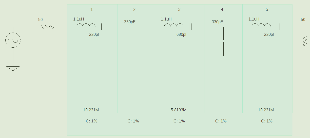
It has been a wet and windy winter's day here so I thought I would take a look at the most problematic filter which is the 30/20M band filter. Staying with the 1.5uH inductors I spent several hours running a number of optimisations and finally came up with ...
1.5uH - 160pF - 300pF - 1.5uH -330pF - 300pF - 1.5uH - 160pF
These values give a definite improvement and takes out the bandpass ripple but unfortunately only one of the original caps can be used (330pF) and it is necessary to find 2 x 160pF and 2 x 300pF. I prefer where possible to stay with the original inductor values and up to this point they seem to be the best choice anyway.
73, Graeme zl2apv
in3otd
Hello,
out of curiosity I have measured the IMD2 of my Hermes-Lite
when, in addition to the two test tones, also additional noise was presented to the ADC. The test signals were at 6.1 MHz
and 8.1 MHz and the IM2 product measured was the sum frequency at 14.2
MHz; the noise added came from my vertical antenna, where the signals in
the 20 meter band were removed using a notch filter to avoid masking
the intermodulation product.
_________
generator_1 o-----| |
| |
|combiner |----.
| | | _________
generator_2 o-----|_________| '----| |
| |
|combiner |----o to Hermes-Lite input
_________ | |
| 20 m | .----|_________|
| band | |
antenna o-----| notch |----'
| filter |
|_________|
The intermodulation product was measured also without any external noise added, connecting a dummy load instead of the antenna.
The results were quite interesting:

with the external noise, the IM2 product is greatly reduced in amplitude, likely spread out over the whole ADC bandwidth by the "dithering" introduced by all the signals present.
So maybe a direct-sampling RX works better (or appears to) when no input filters are used, hi.
73 de Claudio, IN3OTD / DK1CG
Graeme Jury
73, Graeme zl2apv
John Williams
Do you need a RX filter board to test with? I do not recall if I
sent you one. I am a fan of no RX filters on input. I see little
need for it at my QTH.
John -
--
Steve Haynal
Graeme Jury
No thanks, I got one of your original ones and have done all the mods to the filter switching and Peregrine switch inputs as per Glenn.
Thank you for thinking of me.
Cheers, Graeme
John Williams
Sorry Graeme, I should have addressed this to Claudio. So sorry...
John
Graeme Jury
I think I need to make some diagrams etc. to fully answer your questions so this is a brief response to be followed up later.
Your first point. Basically the Rx filters are Ham Band only and the through filter is to be switched in for all other frequencies. i.e. if a ham band filter is selected the through filter is deselected and vice versa. In cases where the second harmonic of the lowest band of a pair can be kept 25 dB or so down the filter is made to cover 2 bands e.g. 60/40, 30/20, 17/15 and 12/10. I am also looking at a roofing filter at 32 MHz amd a flooring filter at 1.7 MHz
Your second point. Yes 17/15 is a pair and we have already got this filter built. The separate filters are old information which has remained but obsolete. I need to make a diagram of what I use for Rx filtering to get things really clear. For Tx filters John W9JSW has a perfectly good set as are the filters on the RS-HFIQ Tx. I have not done any testing to see the effect of the PIN diode switching on harmonic output but of course the relay switching by John is tried and true. The relays have around 1 pF from armature to coil which is the worst case capacitance and reinforces the need to RF ground both sides of the coil with capacitors.
Third point. I got all my toroids from "Toroid King" except for some that Glenn sent me but I have not used them yet.
73, Graeme
On Saturday, July 16, 2016 at 5:39:36 PM UTC+12, Steve Haynal wrote:
Steve Haynal
Alan Hopper

va7...@gmail.com
Hi Claudio,
Steve asked me to provide some input to this discussion, as I tested the Hermes Lite about a year ago.
http://www.ab4oj.com/sdr/hermes_lite/hl_notes.pdf
I agree with your description of the sources of IMD in an ADC. Odd- and even-order products generated by the quantisation process are very likely the main source of IMD until the input power to the ADC is sufficient to drive on-chip analogue stages in the ADC into odd-order non-linearity. This can be seen in the IFSS curve (Fig. 4 on p. 4 of my report). IMD products and reciprocal mixing noise (the latter normally very low in an ADC) are the main components of the idle-channel noise in the Noise Power Ratio (NPR) test.
Dithering and randomisation performed by an on-chip dither generator and randomiser reduce odd-order IMD by de-correlating the IMD products into noise which can degrade the ADC noise floor. The output randomiser may be more useful for offsetting the defect of "hash" from the digital side of the ADC than the dither generator. I have found in the course of testing some SDR's (e.g. the Perseus) that whilst dither reduces the impact of IMD3, it has virtually no effect on DR2 (IMD2 dynamic range). As for "incidental" or "external" dither, I feel that the jury is still out on this. I recently set up a test in which I applied a 2-tone test signal to a Perseus with dither off, measured the IMD amplitude, then injected white noise from my NPR noise generator (with all bandstop filters out) into the third input port on the combiner. As I varied the noise loading, I saw the noise floor increase and decrease with the applied noise level, but the level of the IMD products did not change. When I removed the noise loading and activated internal (on-chip) dither in the Perseus, the IMD product amplitude decreased markedly. This leads me to question the concept of incidental dither, unless my test procedure is in error. I would value your comments.
The main source of severe IMD2 in an on-air receiving environment is a mix between two strong stations outside an amateur band which throws a 2nd-order product into the amateur band. My test plan specifies test signals at 6.1 and 8.1 MHz, which will throw a product at 14.2 MHz. I have found that an RF preselector (either an amateur-band BPF or a suitable 1/2-octave BPF encompassing the amateur band) is required to reduce IMD2 to an acceptable level in these scenarios. Hence the comment in Section C.1 of my report.
I conduct IMD3 and IMD2 with the same test fixture: two signal generators, each driving a 1W MCL amplifier with 30 dB gain. Each amplifier in turn feeds a combiner input via a 15 MHz LPF (for IMD3 tests at 14 MHz) and a 20 dB pad. This configuration assures good isolation between the generators.For IMD2 testing, I use a pair of test frequencies < 15 MHz. If required, LPF's cutting off at lower frequencies can be substituted.
Although I always use the IFSS method for testing IMD3 in SDR's, I still take a single-point measurement for IMD2 testing. This is discussed in a paper i presented at the SDR Academy at Friedrichshafen this year.
http://www.ab4oj.com/sdr/sdrtest2.pdf
If it is desired to use the same receiver for wideband signal analysis, skimming etc. and for narrow-band single-signal reception, a means of bypassing the preselector will be needed. In an RF environment where even-order IMD interference is likely, the preselector will need to be switched in..
73, Adam VA7OJ/AB4OJ
On Sunday, July 17, 2016 at 6:57:07 AM UTC-7, in3otd wrote:
in3otd
I do not have a RX filter board, but I think I won't have much time to experiment with that also, as I'll soon have the PA boards from Steve to test...
73 de Claudio, IN3OTD / DK1CG
in3otd
interesting that the one without the band pass was ahead I would have thought that nevertheless the one with the filter should see a (slightly) lower noise floor caused by any IMD and be slightly better then.
The two radio have the same sensitivity, i.e. the filter losses are negligible (or an equivalent loss is inserted for the radio without filters)?
Do you have the wspr logs to compare the SNRs for the spots received on the two radios?
73 de Claudio, IN3OTD / DK1CG
in3otd
thanks for your detailed comments; I agree with your analysis below about the origin of the intermodulation products.
There are not many details on how the "internal dither" is implemented in the ADC used by Perseus, it may be that it uses a small dither amplitude that is only partially effective, but this is just a wild guess.
Regarding the result of the "incidental dithering" test you did with Perseus, I think that if the origin of the IM2 was "analog", so due to the preamplifier stage where the lower order distortion terms are dominant, you may not see any improvement due to the added noise. I would expect some improvement only in the portion where the IMD is due to the ADC (imperfect) quantization, so at low input levels.
73 de Claudio, IN3OTD / DK1CG
Alan Hopper
in3otd
Hello Steve,
I would say that IMD2 RX products at low interfering
levels are often not a problem in practice, since these are spread out
by the "incidental dithering" caused by the other signals entering the
ADC. This would also explains why users did not notice any particular
issues with RX IMD even without any input filtering, except when the
signals were so strong to drive the ADC into clipping. It is likely that
the RX IMD in practice manifests itself just as an increase in
the noise floor, which can just be mistaken for the noise floor picked
up by the antenna.
In any case, sub-octave filters will improve
the IMD2 performances, also at stronger input levels, where the RxPGA
distortion becomes relevant. The best case would probably be with
sub-octave filters and explicit out-of-band dithering applied, since in this case
we will spread out the ADC IMD and protect the RxPGA from strong
signals. This will also guarantee a predictable dithering: I measured
again the IMD2 with the "incidental dithering" this morning and the
results were of course a little different that those of yesterday
evening, since the signals in the lower bands were not so strong this
time:

Note that the IMD2 at higher input tones levels was not reduced with the lower signals levels present this morning.
Similarly for clipping, as you saw, some limited clipping can probably be tolerated, it will likely just increase a bit the noise floor, which may already be high due to the external noise.
Regarding the combiners, I have used a couple of Mini Circuits ZFSC-2-4 since I had them around but homemade ones will work just as well in the HF bands; some 6 dB hybrids that can be used as splitters/combiners are described on my website (http://www.qsl.net/in3otd/ham_radio/6dB_hybrid_couplers.html) but 3 dB couplers (like the Mini Circuits I used) are nicer because of the lower losses.
73 de Claudio, IN3OTD / DK1CG

James Ahlstrom
Graeme Jury
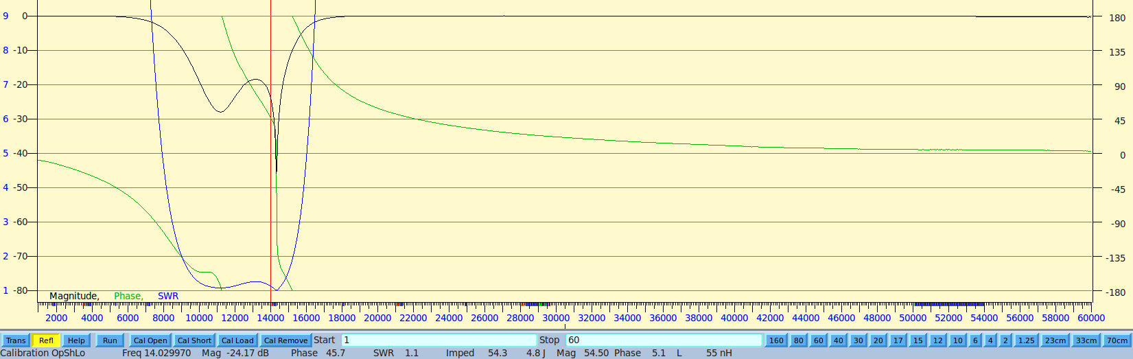
Have been doing some more filter testing on the receive filters and have altered the proposed 30/20 receive filter as it had a funny dip in the passband (see plot from Glenn here). I tried to use as many of the original components as possible so it is not the best that can be done but is not too far. I have attached a plot of the response which includes the loss in the PE4259 switches and a plot with the switches turned off to show the isolation. As can be see there is some spill over in the board and the filter plot takes the general form of the isolated plot in the upper frequency regions. In my past experience it is very difficult to get more than 40 dB isolation across any device without resorting to shielded compartments. When building attenuators I never try for more than 20 dB for any one section.
I replicated this filter with T37-6 toroids and simply used the calculator on the Toroid King site for the turns without bothering to measure them. The filter had an identical response but the passband loss was much better, more than a dB improvement. I am becoming happier with the Peregrine PE4259 switches but am less happy with low Q inductors and want to build a board up with toroids, probably in the T30 size where I do not measure anything but simply construct from calculated turns. It might be a failure but at least I will know if it is possible and if it is worth it. With all the chit chat going on over filters I am starting to wonder if they are worth it at all. I certainly have had outstanding results with my 1.7MHz hi pass and 60 MHz lo pass filters with nothing else except perhaps the lo Q filtering from my antenna tuner. I decided after 50 years of being a tinkerer I would learn CW and go for a DXCC this last sunspot cycle using my SDR. With that filtering it was easily done and so convenient to be able to look anywhere on the bands. This is taking a long time and getting convoluted I am taking on board Jim's N2ADR comment "We should add Rx filters but not over-think it".
73, Graeme ZL2APV
Alan Hopper
in3otd
ah, didn't know of that limitation, maybe it was done to limit the possibility of crosstalk??
Regarding the "incidental dithering", it makes sense that the dithering signal has to be at least comparable to the interfering signals, so all the ADC codes are "swept" by the dithering signal.
This may also be the reason why VA7OJ did not see any effect when using wideband noise: seeing the noise floor increase from the added noise is likely not enough, the added noise amplitude (not the power!) should be at least comparable to the interfering tones amplitude, so much higher than the noise floor. So if noise is used for dithering I think it should not be (too) broadband and most important not in the band of interest.
73 de Claudio, IN3OTD / DK1CG
Steve Haynal
On Sunday, August 7, 2016 at 1:02:23 AM UTC-7, wrote:
Hi Claudio,
Steve asked me to provide some input to this discussion, as I tested the I think there are (at least) 3 differences:
Hermes Lite about a year ago.
http://www.ab4oj.com/sdr/hermes_lite/hl_notes.pdf
I agree with your description of the sources of IMD in an ADC. Odd- and even-order products generated by the quantisation process are very likely the main source of IMD until the input power to the ADC is sufficient to drive on-chip analogue stages in the ADC into odd-order non-linearity. This can be seen in the IFSS curve (Fig. 4 on p. 4 of my report). IMD products and reciprocal mixing noise (the latter normally very low in an ADC) are the main components of the idle-channel noise in the Noise Power Ratio (NPR) test.
Dithering and randomisation performed by an on-chip dither generator and randomiser reduce odd-order IMD by de-correlating the IMD products into noise which can degrade the ADC noise floor. The output randomiser may be more useful for offsetting the defect of "hash" from the digital side of the ADC than the dither generator. I have found in the course of testing some SDR's (e.g. the Perseus) that whilst dither reduces the impact of IMD3, it has virtually no effect on DR2 (IMD2 dynamic range). As for "incidental" or "external" dither, I feel that the jury is still out on this. I recently set up a test in which I applied a 2-tone test signal to a Perseus with dither off, measured the IMD amplitude, then injected white noise from my NPR noise generator (with all bandstop filters out) into the third input port on the combiner. As I varied the noise loading, I saw the noise floor increase and decrease with the applied noise level, but the level of the IMD products did not change. When I removed the noise loading and activated internal (on-chip) dither in the Perseus, the IMD product amplitude decreased markedly. This leads me to question the concept of incidental dither, unless my test procedure is in error. I would value your comments.
The main source of severe IMD2 in an on-air receiving environment is a mix between two strong stations outside an amateur band which throws a 2nd-order product into the amateur band. My test plan specifies test signals at 6.1 and 8.1 MHz, which will throw a product at 14.2 MHz. I have found that an RF preselector (either an amateur-band BPF or a suitable 1/2-octave BPF encompassing the amateur band) is required to reduce IMD2 to an acceptable level in these scenarios. Hence the comment in Section C.1 of my report.
I conduct IMD3 and IMD2 with the same test fixture: two signal generators, each driving a 1W MCL amplifier with 30 dB gain. Each amplifier in turn feeds a combiner input via a 15 MHz LPF (for IMD3 tests at 14 MHz) and a 20 dB pad. This configuration assures good isolation between the generators.For IMD2 testing, I use a pair of test frequencies < 15 MHz. If required, LPF's cutting off at lower frequencies can be substituted.
I think there are (at least) 3 differences: