HLv2 Beta3 PA Mode test result

3,920 views
Skip to first unread message

Takashi K

unread,
Aug 14, 2017, 1:27:32 AM8/14/17
to Hermes-Lite
Hi all,

FYI,
I installed T3 PA transformer and measured PA output spur and IMD.
T3, B62152A4X30 became hot. Is it normal ?

73, Taka  ji1udd
170814_PA_Mode_Spur_IMD.pdf

Steve Haynal

unread,
Aug 14, 2017, 2:00:11 AM8/14/17
to Hermes-Lite
Hi Taka,

Thanks for all the nice .pdf plots. We will have to put these in a place for people to find easily.

T3 becomes warm for me with the new B62152A4X30 on my beta3 and the BN43-202 on my beta2. The temperature rise feels similar to me but I have not made good measurements. Claudio, does your B62152A4X30 heat up too?

I think for the current measurements software can display "<35 mA" if the current reading is low, and only display real measurements if the value is more than ~35 mA. Also, the software can display "PA off" when in receive mode. This will hopefully make it less confusing for a user.

Regarding pure signal, the openhpsdr radios just rely on proximity feedback (no direct connection) from TX to RX. I think there is enough of that happening with the HL2 too. In Quisk, enable the FDX button in the configuration menu. Then when you turn on FDX from the main screen and transmit, you will see the TX signal on the receiver. Sometimes you must lower the LNA gain to prevent clipping.

73,

Steve
KF7O

in3otd

unread,
Aug 14, 2017, 2:00:38 AM8/14/17
to Hermes-Lite
Hello Taka,
thanks for the detailed measurements; at a first glance the PA seems to work as expected.
Regarding T3, I remember checking the transformer temperature when transmitting at 1.8 MHz and 30 MHz for 1 minute or so and while it was certainly warm it didn't seem particularly hot. At which frequency and power level did you test the transformer temperature?

Takashi K

unread,
Aug 14, 2017, 4:05:30 AM8/14/17
to Hermes-Lite
Hi Claudio,

I checked T3 temperature again now.
The test frequency is 14.025MHz and PA output power is around 5W at full power setting (PowerSDR Drive Level 100).
T3 temperture became 55C from 30C when transmitting for 1 minute.
I think there is a possibility that heat is conducted from the transistor.
My beta3 seems less PA output power than Steve's . this is reason ??

73, Taka  ji1udd

Takashi K

unread,
Aug 14, 2017, 4:24:55 AM8/14/17
to Hermes-Lite
Hi Steve,

> We will have to put these in a place for people to find easily.
I made a mistake of  header in the document. so please use revised pdf if you need.
 
> Regarding pure signal, the openhpsdr radios just rely on proximity feedback
> (no direct connection) from TX to RX. I think there is enough of that
> happening with the HL2 too.
Thank you for your explaining. I understood pure signal needs no additional circuit. that's good.

73, Taka  ji1udd
170814_PA_Mode_Spur_IMD_rev1.1.pdf

Steve Haynal

unread,
Aug 14, 2017, 11:23:07 AM8/14/17
to Hermes-Lite
Hi Taka,

Regarding your power output, just to double check, do you have the power limit for each band set to maximum? In Quisk, go to Config--> <Active Radio Name> -> Bands and then set all bands TX level to 255. PowerSDR has a similar configuration screen.

Also, what is the current reading from Quisk when doing spot at full power into a dummy load? I see ~1340mA.

Finally, how are you heat sinking your unit?

73,

Steve
KF7O

Takashi K

unread,
Aug 14, 2017, 10:13:10 PM8/14/17
to Hermes-Lite
Hi Steve,

Thank you for your advice.

> do you have the power limit for each band set to maximum?
I checked that drive level setting. Both are OK.
  Quisk : 255 is set for all bands.
  PowerSDR :  38.8dB is set for all bands in PA setting tab.

> what is the current reading from Quisk when doing spot at full power into a dummy load?
It's 1339mA in my case. and HLv2 total current is 1.92A at 13.8V.

> how are you heat sinking your unit?
Please see the attached photo.
My heat sink is not so good. so I will transmit for a short time under my current evaluation environment.

I forgot to say... I measured T3 (B62152A4X30) inductance by LC-Meter (MARC type) before installed.
 1pin-CT(2pin) and 3pin-CT(2pin) : 11.5uH
 4pin-5pin : 194.8uH
Are these suitable value ?

And I tested by using two different dummy  loads.
If I used 51 ohms dummy load, the voltage was 14.0 Vrms accrding to scope readout, so RF power is 3.8 W. 
If I used 54.7 ohms dummy load, the voltage was 16.4 Vrms, so RF power is 4.9W

73, Taka  ji1udd
test_setup.JPG

Steve Haynal

unread,
Aug 14, 2017, 11:01:39 PM8/14/17
to Hermes-Lite
Hi Taka,

Your lower power output is very puzzling. In Quisk, is the spot level at 100%? You adjust this with the small meter icon to the right of the spot button. Is Quisk set to DGT-U? Is Config->(Your Radio)->Hardware Digital TX Power % set to 100? Is Config->Config TX level and Digital TX level set to 100%? I haven't measured the inductance of T3. But did you build with one loop (inverted U) for each connection from Vpa LDMOS device, and then 4 turns for the antenna side?

73,

Steve
KF7O

Takashi K

unread,
Aug 14, 2017, 11:40:32 PM8/14/17
to Hermes-Lite
Hi Steve,

> In Quisk, is the spot level at 100%?
Yes, it's set to maximum "1.000"

> Is Quisk set to DGT-U?
No, USB mode.

> Is Config->(Your Radio)->Hardware Digital TX Power % set to 100?
It's 20%, but I use USB mode.

> Is Config->Config TX level and Digital TX level set to 100%?
Tx level is 100% and Digital TX level is 20%, but both slider are set to maximum position (fully right).

> But did you build with one loop (inverted U) for each connection from Vpa LDMOS device,
> and then 4 turns for the antenna side?
Yes, I did.

Now, I select DGT-U, Digital TX Power is set to 100%. Digital TX level becomes 100% automatically,
and press "Spot", then no RF output. It seems that I need more setting.

73, Taka  ji1udd

Steve Haynal

unread,
Aug 15, 2017, 12:21:25 AM8/15/17
to Hermes-Lite
Hi Taka,

Even though spot does not need an audio input signal, there must be a good audio input device specified under Config->(Your Radio)->Sound->Digital Input for DGT mode to work. But I tried as you did with USB and see the same power output as DGT, just under 39 dBm on 20M. What is the power output range of your low power RF? By adjusting the Quisk slider, my output will vary from 9.5 dBm to 17 dBm. 

73,

Steve
KF7O

Takashi K

unread,
Aug 15, 2017, 1:01:10 AM8/15/17
to Hermes-Lite
Hi Steve,

> there must be a good audio input device specified under
> Config->(Your Radio)->Sound->Digital Input for DGT mode to work.
I will try later.

> What is the power output range of your low power RF?
I measured my low power RF output using 51 ohms dummy load and scope.
The result is almost same as yours.
 Tx level 0% : Scope shows 1.60Vrms -> 50mW -> arout 17dBm 
 Tx level 100% : 640mV -> 8mW -> 9dBm

Therefore, I think that dirive circuit and mesurement method are no problem.

73, Taka  ji1udd

Steve Haynal

unread,
Aug 15, 2017, 1:08:59 AM8/15/17
to Hermes-Lite
Hi Taka,

Since your low power output looks the same as mine, there is probably no difference in the software setup. Both my beta2 and beta3 produce almost 39 dBm into a dummy load. I guess we will have to see what PA power other beta3 testers see.

73,

Steve
KF7O

Takashi K

unread,
Aug 15, 2017, 1:41:00 AM8/15/17
to Hermes-Lite
Hi Steve,

> I guess we will have to see what PA power other beta3 testers see.
I think so, too.

I took out my old manual antenna coupler from my closet and put it between HLv2 and 51 ohms dummy load.
However, I could not get more output power than 15.2Vrms (4.5W).
PA output transformer setting seems almost best.


73, Taka  ji1udd

in3otd

unread,
Aug 16, 2017, 4:08:12 PM8/16/17
to Hermes-Lite

Hello Taka,
the spectra in the pdf file you enclosed above show a carrier at around -10 dBm on the spectrum analyzer (e.g in the 20 m band), which taking into account the 20 dB + 30 dB of attenuation you had would mean an output of 40 dBm so more than you reported later - not sure which numbers are the right ones, hi.
The inductance values you measured for the transformer look reasonable, at low frequency that core gives about 10 uH/turn^2, with nominally a 30 % tolerance.

I did not yet test the PA here, for the moment I have some measurements on the driver - modified with R55 at 120 ohm:

here is the output power at the fundamental over frequency,  for different drive levels in Quisk:


Flatness is a bit worse than the H-Lv2b2 here, maybe due to the different transformer used - even if also the current one should have enough bandwidth.

Here are the fundamental and harmonics over frequency at max output:


which are comparable to the v2b2, taking into account the lower output.

Out of curiosity, I checked also the driver output after enabling/disabling the PA path and also my H-Lv2b3 did have very little or no output at the beginning, which then increased over time - applying 5.6 kohm resistors to ground to U10 pin5 and U11 pin 5 as suggested solved this issue. A bit puzzling that the H-Lv2b2 here works fine without the additional resistors.

73 de Claudio, IN3OTD / DK1CG

Takashi K

unread,
Aug 16, 2017, 6:19:48 PM8/16/17
to Hermes-Lite
Hi Claudio,

Thank you for sharing your data as always.

> the spectra in the pdf file you enclosed above show a carrier at around -10
> dBm on the spectrum analyzer (e.g in the 20 m band), which taking into
> account the 20 dB + 30 dB of attenuation you had would mean an output of 40
> dBm so more than you reported later
I am aware of it. My test equipments (20dB coupler, ATT, SA) are not commercial products.
So they are not suitable to measure absolute power value.

> - not sure which numbers are the right ones, hi.
Dummy load resistance is measured by D.V.M.
The voltage at dummy is measured by Scope.
DVM and Scope are commercial products, but cheap.
So, I don't know which is right exactly.
If we testers have  a common inexpensive power measurement method,
It would be nice to be able to make a relative comparison.
Do you have any good idea?

> The inductance values you measured for the transformer look reasonable, at
> low frequency that core gives about 10 uH/turn^2, with nominally a 30 %
> tolerance.
Thanks.

> here is the output power at the fundamental over frequency, 
> Here are the fundamental and harmonics over frequency at max output:
I think Low Power Tx is extremely clean.

73, Taka  ji1udd


Message has been deleted

in3otd

unread,
Aug 17, 2017, 5:00:55 PM8/17/17
to Hermes-Lite

Hello,
here are some measurements on the H-Lv2b3 TX IMD; the results look quite good, similar to what measured previously on the H-Lv2b2, taking into account that the drive level to the PA is now lower and its supply is also lower.


The usual ripples in the IMD due to the DC/DC converter behavior can clearly be seen there but should not cause any issue.

I saw once that the TX output was a few dB lower than expected, not sure if because I did not stop the measurement script properly and left the H-L in some "undefined state" but after turning the board off and on again everything was fine. Not sure if this is similar to what Taka saw.


73 de Claudio, IN3OTD / DK1CG


Steve Haynal

unread,
Aug 18, 2017, 1:54:28 AM8/18/17
to Hermes-Lite
Hi Claudio and Taka,

Was your peak output about 39 dBm? If your unit drops by a few dBm again, please check if the TxDAC level adjustment is still working. Once or twice this has stopped for me and I suspect the SPI communication to the AD9866 is not 100% and needs to be improved a bit.

Taka, where did you source your core for T3? You have mentioned heat and lower power. Perhaps there is some difference with your core.

73,

Steve
KF7O

Takashi K

unread,
Aug 18, 2017, 4:22:53 AM8/18/17
to Hermes-Lite
Hi Steve,

> where did you source your core for T3?

I bought TDK B62152A4X30 at Arrow Electronics Inc.

73, Taka  ji1udd

in3otd

unread,
Aug 18, 2017, 4:14:08 PM8/18/17
to Hermes-Lite
Hello,

here is the H-Lv2b3 PA output vs frequency for the various TxPGA settings:


and here are the harmonics at maximum output (TxPGA 15):


the output is not as flat as in the H-Lv2b2, likely die to the driver, as said in the other post.
Harmonics are relatively low, maybe a little better than seen previously.


73 de Claudio, IN3OTD / DK1CG

in3otd

unread,
Aug 18, 2017, 4:33:23 PM8/18/17
to Hermes-Lite
Hello Taka,
I've checked again the T3 transformer temperature: at 14.2 MHz and full PA output (about 8.3 W) after about 2 minutes of transmission it actually gets quite warm: I did not measure it yet but it feels to the touch at least as warm as the AD9866, so maybe around 45 C.


73 de Claudio, IN3OTD / DK1CG

Takashi K

unread,
Aug 19, 2017, 3:51:26 PM8/19/17
to Hermes-Lite
Hi Steve, Claudio and all,

I have found that Vrms readout on my scope depends on horizontal range selection (not
vertical). like this,
horizontal range : Vrms readout : calcurated power
  5ns : 18.4V : 6.6W
 25ns: 17.2V : 5.8W
250ns : 16.0V : 5.0W
freq. is 14.2MHz. maybe digital sampling issue.

Also I made RF probe that I found Fig2 and Fig3 on AB4OJ website. I used 1N34A diode and 51 ohms load.
I got 1.62V as DMM readout. so RF power was 6.4W. Of course, this RF probe also has some errors.
But it seems that my RF full power on 20M is around 6.5W.

73, Taka  ji1udd

Alan Hopper

unread,
Aug 21, 2017, 4:30:26 PM8/21/17
to Hermes-Lite
Hi beta3 testers,
I'm back on solid ground and ready to test the pa, I'm aware there are some mods todo, in terms of moving to a release version what mods can I most usefully test?
73 Alan M0NNB

Steve Haynal

unread,
Aug 21, 2017, 6:59:41 PM8/21/17
to Hermes-Lite
Hi Alan and Group,

Glad you are back! Sorry I've been silent the last few days. The solar eclipse path of totality was only ~45 miles from my house, so we had to go to a relative's house, camp and watch the event. The 1 minute 56 seconds of totality was probably a once in a lifetime event for me. Quite spectacular. I brought my Hermes-Lite 2beta3 and had it running WSPR automatically during the eclipse. 40M felt more like evening than mid morning. I also had my Hermes-Lite 2beta2 running WSPR receive at home.

There are 3 modifications recommended for beta3 so far:

* Change resistor in op amp from 75 to 120 Ohms to reduce gain and better batch PA.
* Add 5K resistors to shared port of both PE4259 to ground for proper switching.
* Bypass opamp for temperature and current channels.

I will document these later today or this week. You can search the list for discussion.

73,

Steve
KF7O

Takashi K

unread,
Aug 25, 2017, 8:17:57 AM8/25/17
to Hermes-Lite
Hi Steve, Claudio and all,

My PA issue (a bit lower RF power) has been solved.
The cause was that T3 2nd coil is shorted to T3 core.
T3 core, B62152A4X30 is conductor, not same as BN43-202.
I was using UEW wire but shorted with core.

Now I use FEP wire for T3. See the attached photo.
I measured PA output power by AB4OJ method that I mentioned before.
80M : 1.65V -> 7.9W
20M : 1.66V -> 8.0W
15M : 1.53V -> 6.9W
10M : 1.45V -> 6.3W

73, Taka  ji1udd
T3.jpg

in3otd

unread,
Aug 25, 2017, 11:06:58 AM8/25/17
to Hermes-Lite
Hello Taka,
glad to know that your PA is working fine now - you actually get a little more power than I here now, hi.
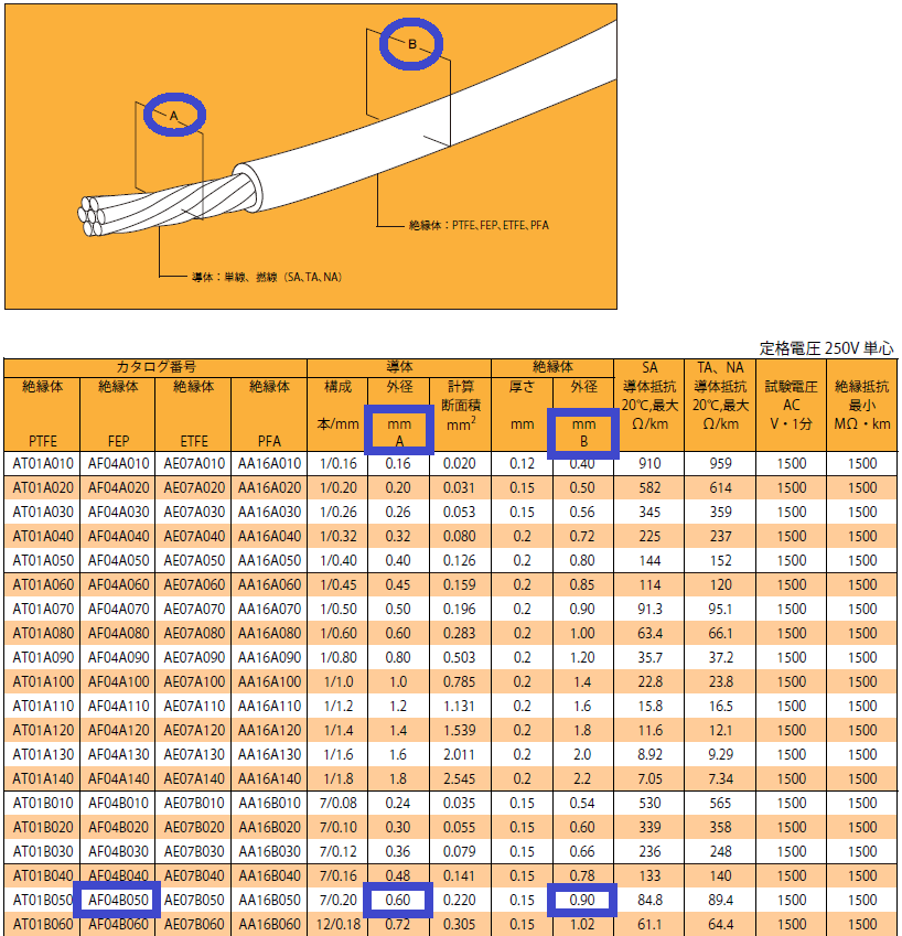
It's true that the core has a very low resistivity and a wire touching the core could cause issues. Using FEP wire will be the best solution (and it's always silver plated, AFAIK), maybe we could ask the manufacturer to include a short length of wire with the H-L.

Out of curiosity, is the new transformer getting hot as the old one during your tests?


73 de Claudio, IN3OTD / DK1CG

Takashi K

unread,
Aug 25, 2017, 8:00:00 PM8/25/17
to Hermes-Lite
Hi Claudio,

> maybe we could ask the manufacturer to include a short length of wire with the H-L.
I use FEP wire Junkosha AF04B050 (SA). I attaced the specification.

> is the new transformer getting hot as the old one during your tests?
The core tempreture increaces only 10C when transmitting for 1 minute.
Before fixed, it was 25C. so improved !

73, Taka  ji1udd

Takashi K

unread,
Aug 25, 2017, 8:01:44 PM8/25/17
to Hermes-Lite
I forgot to attache the file.

2017年8月26日土曜日 9時00分00秒 UTC+9 Takashi K:
junkosha_af04b050.png

Graeme Jury

unread,
Aug 25, 2017, 9:32:23 PM8/25/17
to Hermes-Lite
I have been using wire wrap wire with good results. It is single strand silvered wire and for bigger cores I parallel 4 or 5 strands.

73, Graeme zl2apv

Takashi K

unread,
Aug 26, 2017, 5:13:37 AM8/26/17
to Hermes-Lite
Hello Graeme-san,

> I have been using wire wrap wire with good results. It is single strand silvered wire
> and for bigger cores I parallel 4 or 5 strands.

That's good idea! but this time, it seems difficult for amateurs because the core B62152A4X30 is small.
High skill is needed :)

73, Taka  ji1udd

Steve Haynal

unread,
Aug 28, 2017, 12:55:02 AM8/28/17
to Hermes-Lite
Hi Taka,

Thanks for solving this issue. I'm sure someone else in the future will run into the same problem so it is very good to know the solution. I will ask Elecrow about including some FEP wire in the next run where I'd like Elecrow to ship directly to buyers.

73,

Steve
KF7O 

Steve Haynal

unread,
Aug 28, 2017, 1:22:18 AM8/28/17
to Hermes-Lite
Hi Claudio,

At the end of this post you say, "the output is not as flat as in the H-Lv2b2, likely die to the driver, as said in the other post"

I couldn't find the other post. Can you please provide more details?

73,

Steve
KF7O

in3otd

unread,
Aug 28, 2017, 4:06:50 AM8/28/17
to Hermes-Lite

Hello,
I was referring to the post just above where the driver output is plotted vs. frequency; in the H-Lv2b3 the driver output peaks at about 17 dBm at 14 MHz and goes down to 15 dBm at 30 MHz. In the previously measured drivers the drop at high frequency was quite less; a summary of the measured PA drivers outputs for the various versions is in the graph below


note that I have added 3.57 dB to the H-Lv2b3 driver output to account for the lower gain due to the R55 change. I'm somewhat surprised by the close agreement at low frequency, hi. But at the upper end the H-Lv2b3 driver output is about 1 dB less than previously seen, starting from about 25 MHz.
I tried restoring R55 to the old 75 ohm value but the output vs. frequency curve shape did not change at all, just shifted up as expected. I've also changed the MABAES0060 transformer with the BN43-2402 one I've used previously but again the output stayed the same - so this confirms that this transformer is working well. At this point I do not know why the H-Lv2b3 driver output drops above 25 MHz, it could be that the components in the filter ahead of the driver have too much tolerance or a value is wrong but I did not yet try to desolder and measure them.

Alan Hopper

unread,
Aug 29, 2017, 6:57:38 AM8/29/17
to Hermes-Lite
Hi List,
I've just done a better test on my beta3 pa.It appears I have too much drive in spite of changing r55. With everything at max in Spark
I get
80m 10.1W
20m 10.2W
15m 10.2W
10m 9.8W

T3 get very hot at these powers and the output is not very clean, I only tested for seconds.  If I limit the drive to give 6W T3 is still rather hot (hotter than anything else). The temp sensor is at 49C after 5 minutes of tx.  I've used the peak to peak reading from the scope to measure power, I also found the scope rms reading to give different results.  In winding T3 I noticed it had rather sharp burs that stripped the enamel so I debured it and did it again before any of my tests. I shall try and track down why I have too much drive.
73 Alan M0NNB

Alan Hopper

unread,
Aug 29, 2017, 8:44:58 AM8/29/17
to Hermes-Lite
Hi List,
I appear to have 0.22W from the low power output into a 50ohm load. If I measure at the input and output of one half of the op amp I get 0.83Vpp in and 5.2vpp out, if I'm reading the data sheet correctly (a big if) this looks like the right amount of gain.  The gain setting resistors all have the correct values printed on them.  Maybe I'm doing something silly measuring power but the behavior at 6W (clean) and 10W makes me think I'm in the right ballpark.
73 Alan M0NNB

Steve Haynal

unread,
Aug 30, 2017, 12:05:08 AM8/30/17
to Hermes-Lite
Hi Alan,

It sounds as if there is something wrong with your preamp to make it run with higher output. Even though the resistors have the correct values on them, what do you measure with a Ohm meter? These values are low enough that you should see something close or maybe uncover a short. I'd verify the following:

R55 == 120
R56,R59 = 330
R52,R62 = 12
B75,B70,B77 = open to DC

73,

Steve
KF7O

Alan Hopper

unread,
Aug 30, 2017, 1:32:30 AM8/30/17
to Hermes-Lite
Hi Steve,
thanks, I checked all those with an Ohm meter and they appear correct, I also checked both op amps had the same signals and gain.  Is my measured voltage gain of 6 what you would expect or is it too high?  Could I possibly be getting a higher output from the dac due to software issues?  Would it be useful to document a set of expected signals at various points across the board.

73 Alan M0NNB

Alan Hopper

unread,
Aug 30, 2017, 5:17:16 AM8/30/17
to Hermes-Lite
Hi Steve,
I just installed Quisk and got the same high output once the spot level and tx level were set to max.
73 Alan M0NNB

in3otd

unread,
Aug 30, 2017, 5:47:49 AM8/30/17
to Hermes-Lite
Hello Alan,
can you measure the output power vs frequency and compare with the graphs I posted previously, to check if the filter is working fine or some components there is wrong? The driver output will saturate at about 23 dBm and the distortion will increase rapidly near that level.


73 de Claudio, IN3OTD / DK1CG

Takashi K

unread,
Aug 30, 2017, 6:49:18 AM8/30/17
to Hermes-Lite
Hi Alan,

Could you check R69 and R102 (1.6k ohms) that Elecrow reworked this time ?
Are they soldered correctly ?

73, Taka  ji1udd

Alan Hopper

unread,
Aug 31, 2017, 5:16:09 AM8/31/17
to Hermes-Lite
Hi Taka, Claudio and Steve,
thanks for all the help, the mystery is solved, my dummy load had gone open circuit which I think explains everything. 
Thanks again (I'm feeling rather the dummy right now).
73 Alan M0NNB  

Steve Haynal

unread,
Aug 31, 2017, 11:33:09 PM8/31/17
to Hermes-Lite
Hi Alan,

Thanks for providing a PA test with no load! I've been hesitant to do open/short tests as they may be destructive and I want the firmware guards in place first. Do you want to try a shorted test? :)

73,

Steve
KF7O

Alan Hopper

unread,
Sep 1, 2017, 1:58:08 AM9/1/17
to Hermes-Lite
Steve,
I'm happy to volunteer to be a fault condition tester as I appear to have a natural aptitude for it:)  
73 Alan M0NNB 

Alan Hopper

unread,
Sep 1, 2017, 7:07:31 AM9/1/17
to Hermes-Lite
Hi list,
I just tested T3 after my unplanned open circuit testing and the coils are now shorted to the core so it obviously got hot enough for the enamel to soften, I had tested before and they were ok.

Taka, do you have a spec or part number for your wire? 

73 Alan M0NNB

p.s. an easy way to unsolder T3 is to snip the coils at the top of the core, remove the core and unsolder the wires 1 at a time.

Takashi K

unread,
Sep 1, 2017, 7:28:16 AM9/1/17
to Hermes-Lite
Hi Alan,

I have already posted my T3 wire information on this thread.
I'm using Junkosha AF04B050 (SA).
Maybe Junkosha is not popular out side of Japan.
For more detail, please check my attached file on my previous post.

73, Taka  ji1udd

Alan Hopper

unread,
Sep 3, 2017, 10:27:12 AM9/3/17
to Hermes-Lite
Taka,
thanks, sorry I was lazy and did not look properly.

With a new dummy load and T3 wound with ptfe wire of the same size as Taka's I get
80m 6.3W
20m 7.3W
15m 6.3W
10m 5.9W

After 5 minutes on full power the temp sensor reads 40C, and nothing is over hot.

73 Alan M0NNB

Steve Haynal

unread,
Sep 4, 2017, 12:27:50 PM9/4/17
to Hermes-Lite
Hi Alan,

Great to hear your problems are solved. My HL2 developed the hot T3 issue and I measure resistance from the core body to one of the pins now. I am looking for some small enough guage wire with high temperature insulation that is available locally. I don't want to wait for a DigiKey order. What did you end up using?

I see you have some roll-off on 10M too. We didn't see that much with the beta2. Claudio isolated it to the preamp before the low power transformer. I've been comparing with my beta2 and haven't found a single reason yet. The output from the AD9866 looks a little lower and the gain of the OP2677 looks a little less too.

73,

Steve
KF7O

Alan Hopper

unread,
Sep 4, 2017, 12:33:25 PM9/4/17
to Hermes-Lite
Steve,
I used the 7*0.2 ptfe wire from here https://www.wires.co.uk/acatalog/cu_sp_ptfe.html it is a good fit.
73 Alan M0NNB 

Steve Haynal

unread,
Sep 8, 2017, 12:51:26 AM9/8/17
to Hermes-Lite
Hi Claudio and Group,

This lower power output in beta3 for 10M and 12M appears to caused by poor RF specs of the resistors used in the Elecrow assembly. Initially my beta3 low power RF output on 10M was 15.2dBm. I replaced R56 and R59 with 330Ohm Yageo resistors I used in my beta2 build. The output went up to 16dBm. Then I replaced R57 and R58 with Yageo 1K and the output went up to 16.6dBm. This is closer to the 17.4dBm I see on my beta2. There may be a few more resistors (R50 and R64?) affecting output. We will have to specify resistors with better RF performance on RF paths in future assemblies.

73,

Steve
KF7O

Steve Haynal

unread,
Sep 8, 2017, 1:17:34 AM9/8/17
to Hermes-Lite
The 330Ohm part number used by Elecrow is 0603WAF3300T5E. It is from their free components list. I only got a few hits for this part number, none on www.octopart.com. The one datasheet I looked at didn't list any RF characteristics. I suspect their is significant parallel capacitance which degrades the resistance as frequency increases.

73,

Steve
KF7O

Takashi K

unread,
Sep 8, 2017, 5:30:07 PM9/8/17
to Hermes-Lite
Hi Steve and all,

 I replaced R56, R59, R57 and R58 with KOA RK73B Series, but nothing changed at all.
KOA resistor characteristics is here.
I don't have another 0603 resistor, so I waiting for reports from other testers.

73, Taka  ji1udd

in3otd

unread,
Sep 8, 2017, 6:23:39 PM9/8/17
to Hermes-Lite
Hello,
I replaced just R56 and R59 for the moment,  I still get the same power output over frequency. Measuring the resistors with a VNA, the ones originally mounted and the Yageo used as replacements look practically identical - with just a parallel parasitic capacitance around 0.5 pF.


73 de Claudio, IN3OTD / DK1CG

Steve Haynal

unread,
Sep 9, 2017, 12:11:38 AM9/9/17
to Hermes-Lite
Hi Claudio and Taka,

I went back and remeasured with two different dummy loads, two different scope probes and also  compared again with my beta2. I am still seeing more power now on 10M with my beta3. Maybe I deformed the PCB when I was replacing resistors. I also replaced B75 and resoldered the thermal pad of U9 but noticed no power increase after those steps. Maybe I overheated the inductors, but I replaced resistors R56 and R59 first, which are not near the inductors, and saw a power increase just from that. 

When I removed R57 and R58, I measured output with those resistors gone. Power output was definitely higher. I think Claudio helped with that filter design and the resistors were to balance output across the spectrum. Maybe we need to revisit this filter design?

The OP2677 looks authentic. The lettering is identical to the one on my beta2. I may have an extra one and try replacing it.

T1 is not suspect as Claudio eliminated it. Also, I see reduced power on the PA path for 10M which does not include T1.

The PE4259s definitely behaved differently from beta2. Maybe there is attenuation here are both paths.

I considered putting a capacitor in parallel with R55 (or series resistor-capacitor in parallel with R55) such that the gain is increased for higher frequencies. This will not be good for harmonics though.


73,

Steve
KF7O

Steve Haynal

unread,
Sep 9, 2017, 1:08:33 AM9/9/17
to Hermes-Lite
Hi,

Just to experiment I reheated and applied a bit more solder to all U9 pins and the surrounding RF components. I thought there might be some bad solder connects, etc. in the area. I saw no increased output after this.

73,

Steve
KF7O

Steve Haynal

unread,
Sep 9, 2017, 2:16:24 AM9/9/17
to Hermes-Lite
Hi Alan,

I had a hard time finding sources for this type of wire. I ended up ordering from ebay: https://www.ebay.com/p/solid-silver-wire-22-awg-fpe-insulation-teflon-dielectric-500-feet/1740729388?_trksid=p2047675.l2644

Pretty expensive at $4.50 per foot. I didn't understand if your site offered a full spool or some short length per the price listed.

My beta3 PA is now operational again.

73,

Steve
KF7O

Steve Haynal

unread,
Sep 9, 2017, 2:22:21 AM9/9/17
to Hermes-Lite
Hi,

My replacement of R56 and R59 was pretty sloppy. One filled the via near pin 2 of U9 with solder. The via drill sizes look smaller on the beta3 boards vs the beta2 boards. I wonder if there is some inductance there. This inductace may matter as these vias go to R55 and B75.  Can you try filling the vias near pin 2 and 6 of U9 with solder to see if this makes a difference? You may have to access one of the vias from the bottom side.

73,

Steve
KF7O

Takashi K

unread,
Sep 9, 2017, 4:26:07 AM9/9/17
to Hermes-Lite
Hi Steve,

I filled the vias near pin 2 and 6 of U9 with solder, but nothing changed.
Also I added a 0.01uF 100V G0G/NP0 capacitor in parallel to B75, but it did not have any effect.

73, Taka  ji1udd

Alan Hopper

unread,
Sep 9, 2017, 9:59:42 AM9/9/17
to Hermes-Lite
Steve,
yes I also had problems finding something at a reasonable price that would be delivered quickly.  I could not find fep insulation and am not clear as to how it is different to ptfe. My roll was 10m for £6.58 . http://wires.co.uk are handy in the UK for small rolls of all sorts of wire.
73 Alan M0NNB


On Saturday, September 9, 2017 at 7:16:24 AM UTC+1, Steve Haynal wrote:
Hi Alan,

Steve Haynal

unread,
Sep 9, 2017, 1:43:54 PM9/9/17
to Hermes-Lite
Hi Alan,

That is a much better price than I found. I will have to do some more looking for a better supply here and in China.

73,

Steve
KF7O

Steve Haynal

unread,
Sep 9, 2017, 1:47:55 PM9/9/17
to Hermes-Lite
Hi Taka,

Thanks for trying. Now that my beta3 PA is operational again, I actually don't see improvement through the PA path on 10M. I still see the improvement on the low power path though. On the low power path, what do you and others measure into a dummy load when running Quisk spot at full (low power) output on 28.076 MHz? Now I measure 4.35V peak to peak or 16.7 dBm. In the past it was 3.65V peak to peak, or 15.2 dBm. The past reading agrees with data Claudio posted earlier.

73,

Steve
KF7O

in3otd

unread,
Sep 9, 2017, 4:41:26 PM9/9/17
to Hermes-Lite

Hello,
today I removed all the PA driver input filter components and measured them on a VNA; from what I could see they looked ok and quite similar to the ones I used for the H-Lv2b2 - except maybe the capacitors, for which it was difficult to precisely measure the losses/Q.
Since I suspected that some/all of the capacitors might not have a very high Q, I changed them all (C49, C50, C51 and C52) with the spares I had from the previous build. Besides R56 and R59, which were changed previously with no measurable effect, I didn't change anything else.
This made quite a difference on the PA output level flatness:


and here is a comparison with the H-Lv2b2 output (here have added 3.57 dB to the H-Lv2b3 driver output to account for the lower gain)


so now the PA driver output flatness is practically the same as on the H-Lv2b2.

Since I changed all the caps together I do not know if there were just 1 or 2 caps which caused the high-frequency level drop. If you would like to experiment changing the driver filter caps on your H-Lv2b3, you may use the RX at minimum gain and an additional 30 dB or 40 dB of attenuation to check the PA driver level; the absolute values may be off due to the RX response being not completely flat but you should be able to compare the effect on the PA driver output when changing some component.

I'll later check how the PA output flatness looks like after these changes.


73 de Claudio, IN3OTD / DK1CG


Steve Haynal

unread,
Sep 9, 2017, 7:20:38 PM9/9/17
to Hermes-Lite
Hi Claudio,

Very interesting. I exchanged the capacitors on my beta3 and saw improvement too. In my measurements below, I am reporting Volts peak to peak across the same dummy load connected to the low power RF output. I am using Quisk spot at 28.076MHz with spot at 100% and the TX DAC output at 100%. 

* 4.35Vpp before any changes. My initial measurement several days ago before changing resistors was 3.65Vpp.

* 4.45Vpp after changing C49. I measured the removed capacitor and it was close to 70pF, in range of 5% tolerance, although my meter is not the best.

* 4.3Vpp after changing C50. I was surprised by this drop. The removed capacitor was 143pF, again within tolerance.

* 4.65Vpp after changing C51. The removed capacitor was also 143pF. This is just outside of tolerance. The measurement was exactly the same as C50. I measured several times and the meter gave a stable reading. I suspect the assembly house may have substituted 150pF here as it is so close to 160pF. There appears to be sensitivity between C50 and C51.

* 4.65Vpp after changing C53. The removed capacitor was 100pF. 


If someone is to do this experiment again, it would be interesting to start with C51. My beta3 board has seen about as much rework in this area of the PCB as it can tolerate.

I see higher output from the PA on 10M now, ~6.5W or 38.2dBm.

It is possible given the 5% tolerance of the capacitors that C51 may be as low as 152pF and C50 as high as 157.5pF. For the filter designers, how will this affect the filter? Should we specify some slightly different values here? I don't really want to go to 1% capacitors if possible as the price is 5x, but 5x of $0.10 is not too much. 160pF. 160pF is a little harder to find.

The Elecrow free parts list has 0805B151K500NT for the 150pF 0805 capacitor 10%, which hopefully they didn't use. In the BOM I specified:

150pF 0805 NP0>=50V<=5%  CC0805JRNPO0BN151 C50 805 2 http://www.octopart.com/search?q=CC0805JRNPO0BN151
160pF 0805NP0>=50V<=5% GRM2165C2A161JA01D Y C51 805 2 1 http://www.octopart.com/search?q=GRM2165C2A161JA01D

but with substitutions okay. We can at least tighten up the BOM here to no substitutions.


73,

Steve
KF7O

Takashi K

unread,
Sep 10, 2017, 1:19:49 AM9/10/17
to Hermes-Lite
Thanks for your investigation, Claudio.

RF output power on higher frequency was improved by replacing C50 and C51.
The mounted C50 and C51 look like 150pF 10% capacitor.

73, Taka  ji1udd
170910_TxLPF_capacitors_replacement.pdf

Steve Haynal

unread,
Sep 10, 2017, 2:35:18 AM9/10/17
to Hermes-Lite
Hi Taka,

Thanks for your data. From you experience and mine, it makes me think that the problem is more about C50 and C51 both being 150pF with wide tolerance rather than low Q of the capacitors used. This can be fixed by not allowing substitutions in the BOM for these parts, or insisting that the substituted parts meet value and tolerance specifications. Elecrow was very good for parts with no substitutions allowed such as the inductors used in this filter. What do others think?

73,

Steve
KF7O

in3otd

unread,
Sep 10, 2017, 7:10:20 AM9/10/17
to Hermes-Lite

Hello Steve,

as you said, the issue very likely comes from the actual capacitor values; I did too many measurements yesterday and overlooked the actual measured values for the filter components I removed:
C49 : 72.5 pF, -3.4 % w.r.t. the 75 pF nominal
C50 : 153 pF, +2 % w.r.t. the 150 pF nominal
C51 : 143 pF, -10,6 % w.r.t. the 160 pF nominal
C52 : 99.5 pF, -0.5 % w.r.t. the 100 pF nominal

so the measured C51 value is way out of tolerance.

The PA driver simulations done some time ago never matched exactly the measurements but out of curiosity I re-simulated the driver filter response with the nominal and the actual C51 value.
This is the response with the filter nominal values


the simulation results have less ripple and drop at the high end but the peaks and valleys are more or less at the right position.

Here is a comparison between a simulation with C51 set to 143 pF and the H-Lv2b3 driver output before reworking the filter:


again, the response is a bit different but the general trend is the same.
So I'll say that very likely the issue, at least on my board, came from the wrong C51 value and is not related to the capacitors quality/losses.
Maybe they mistakenly installed a 140 pF capacitor on all the boards for C51, instead of 160 pF or even mixed up more values in the filter area in the other boards.
I wonder if it makes sense to use 150 pF in parallel with 10 pF, as these values are already in the BOM to avoid the non-standard 160 pF.


73 de Claudio, IN3OTD / DK1CG

Alan Hopper

unread,
Sep 11, 2017, 8:05:04 AM9/11/17
to Hermes-Lite
Hi list,
At maximum drive my HL2_b3 is just starting to clip which explains why my power is a little down compared to Taka's ( especially on 80m).  Vpa is 7.8v, what vpa do others have?
73 Alan M0NNB

Steve Haynal

unread,
Sep 11, 2017, 12:10:25 PM9/11/17
to Hermes-Lite
Hi Alan,

7.8V should be fine. My early tests were at 7.5V. How are you detecting clipping? The HL2 firmware was set for maximum output when Quisk is set to spot at 100%. I am starting to suspect that Quisk 100% spot is not maximum audio input. Recently with WSJTX I also see clipping unless I lower the output by a few ticks with the slider at the right. If Spark SDR is setup to "spot" at max audio, I will adjust the firmware FIR filter to treat that as maximum possible audio input.

73,

Steve
KF7O

Alan Hopper

unread,
Sep 11, 2017, 1:36:37 PM9/11/17
to Hermes-Lite
Steve,
Thanks, I see clipping/ flat topping on the scope on 80m and other distortion starting to appear on other bands, it is not there on the output of the op amp. I see the same with Quisk, the distortion starts with the spot level at about 0.9 and the same in Spark with the Sig screen so I think they produce near identical levels.  

73 Alan M0NNB

Steve Haynal

unread,
Sep 12, 2017, 12:43:53 AM9/12/17
to Hermes-Lite
Hi Alan,

In full-duplex do you see the TX distortion with RX monitoring too? Is your scope clipping? I haven't seen this. Even with 7.8V you should have enough headroom for 38-39 dBm output provided you have a fairly well matched load. If you want to try raising the voltage, you can refer to the datasheet and compute new resistor values for voltage setting.

73,

Steve
KF7O

Alan Hopper

unread,
Sep 12, 2017, 3:11:57 PM9/12/17
to Hermes-Lite
Steve,
thanks, I'm pretty sure it is not the scope ( no prob with the higher voltages from my open circuit test:)) but I'll check  . It's useful to know it is not normal and it is good rf education trying to track down the cause.  I shall persevere.
73 Alan M0NNB

On Tuesday, September 12, 2017 at 5:43:53 AM UTC+1, Steve Haynal wrote:
Hi Alan,

Alan Hopper

unread,
Sep 15, 2017, 7:44:15 AM9/15/17
to Hermes-Lite
Steve,
I've not really got to the bottom of this and why it is different to others. I changed r19 to 18k to give me 8.8v vpa and this improved things
80m 7.03W
20m 8.33W
15m 6.72W
10m 6.22W (no filter cap mod yet)
I still see a tiny bit of clipping just starting. I've tried two dummy loads and sets of leads.  Before the mod the centre tap of t3 had about 400mv ripple on at full drive and was dropping to 7.6v at the peaks of the output waveform, I assume my transformer core is the same as yours.  Could my relay or sma be faulty?

73 Alan M0NNB 

Steve Haynal

unread,
Sep 15, 2017, 10:57:20 AM9/15/17
to Hermes-Lite
Hi Alan,

Can you provide one frequency and set of software settings where clipping is the worse for you? I will test the same here, including Vpa, and maybe Taka and Claudio will do the same. 

Maybe there is something broken with your 8.0V supply. Have you inspected all the components associated with that supply?

73,

Steve
KF7O

Alan Hopper

unread,
Sep 15, 2017, 11:48:43 AM9/15/17
to Hermes-Lite
Steve,
thanks, it is most obvious at 3.8MHz, vpa measured at t3 centre tap has 400mvpp ripple and a minimum of 7.6V, this is with 100% spot in Quisk or max level in Spark Sig mode.  This weekend I'll lift of T3 and put the load directly on it in case something else is adding a load. I did wonder if there was something wrong with my current measurement and bias settings but it does seem to agree with other peoples values. Reducing the bias does slightly reduce the clipping, I guess I'm swapping foot room for head room, I'll double check the current with T3 lifted. Everything looks ok around the vpa supply.

73 Alan M0NNB

Steve Haynal

unread,
Sep 15, 2017, 11:52:42 AM9/15/17
to Hermes-Lite
Hi Alan,

I will measure this in a few days as I am away form my setup currently. The 400mvpp ripple sounds very suspicious. I think Claudio measured this power supply carefully at one point in the past and found it clean. Is you main power supply dropping under load? Are all the filter capacitors for Vpa installed in your build?

Yes, I am using the same T3 core as you, from the same Digi-Key order.

73,

Steve
KF7O

in3otd

unread,
Sep 15, 2017, 12:05:11 PM9/15/17
to Hermes-Lite
Hello,
I remember measuring on the H-Lv2b2 and there the supply was quite clean - actually a bit cleaner at high current than at low current, due to the DC/DC pulse skipping, IIRC.

Alan, can you try to simply load the DC/DC with a resistor, there should be no need to remove T3, if you set the bias to zero; the current monitor is quite precise down to 10 mA or less, once you remove the opamp in the path, so you can also use that to double check the load the DC/DC is seeing.


73 de Claudio, IN3OTD / DK1CG

Takashi K

unread,
Sep 15, 2017, 4:52:03 PM9/15/17
to Hermes-Lite
Hi Alan,

Have you checked the resistance of R123 using Ohm meter?
Was it 0.04 ohms or lower ?

73, Taka  ji1udd

in3otd

unread,
Sep 16, 2017, 3:25:48 AM9/16/17
to Hermes-Lite
Hello Alan,
I've measured the PA output and the Vpa level on my H-Lv2b3 and at a first glance they seem fine:


Vpa above was measured on the vias near T3 and B100; with no load it measures 8.0 V.
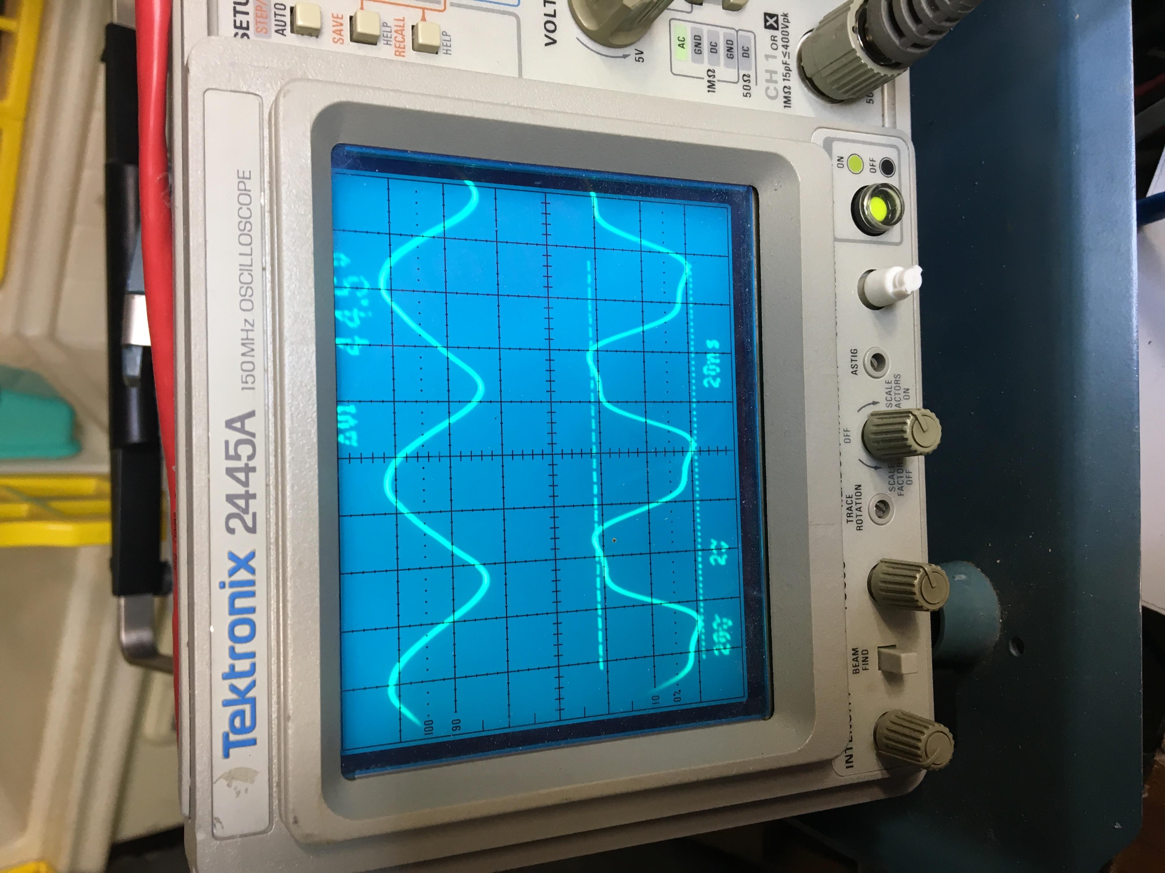
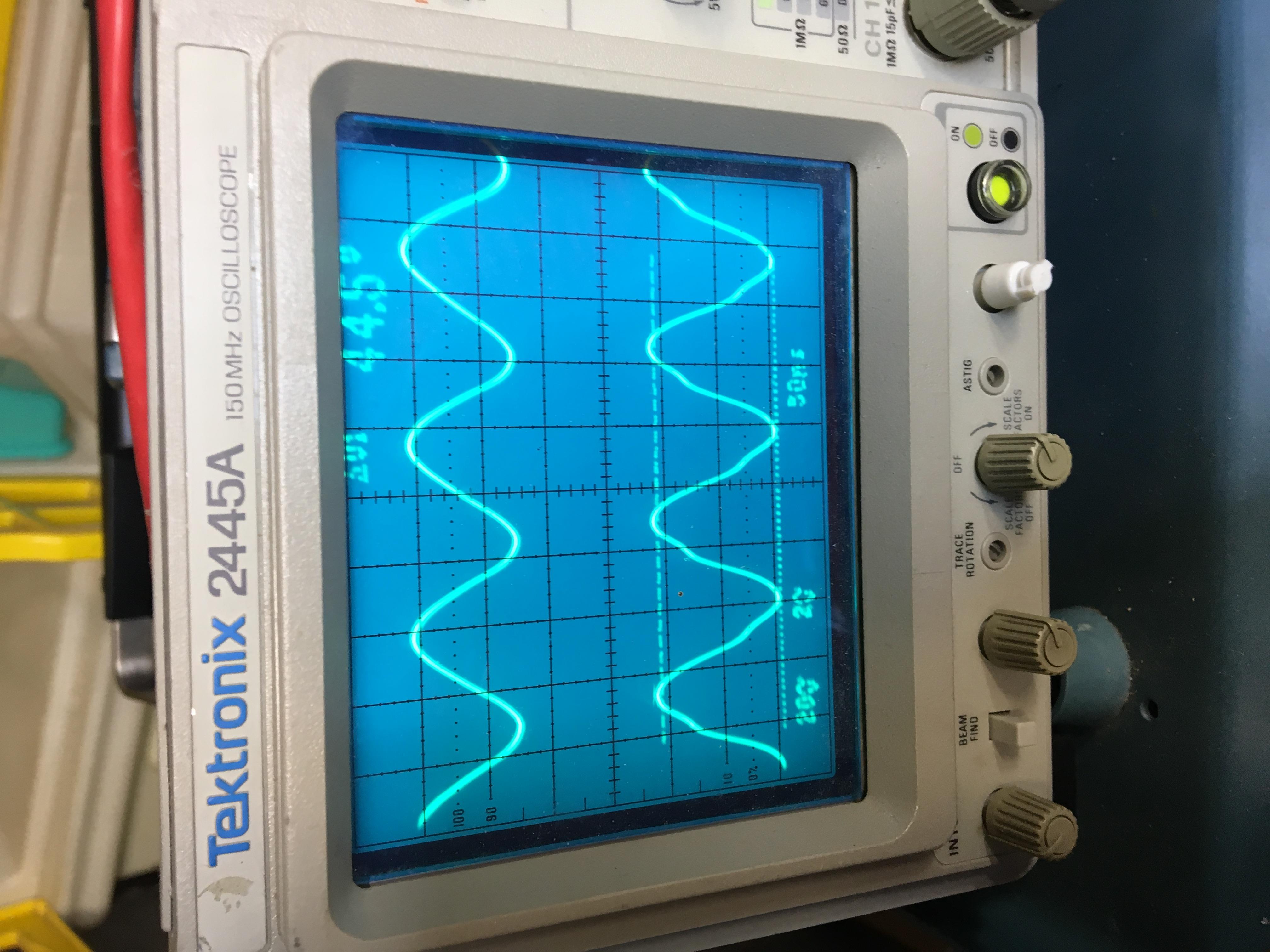
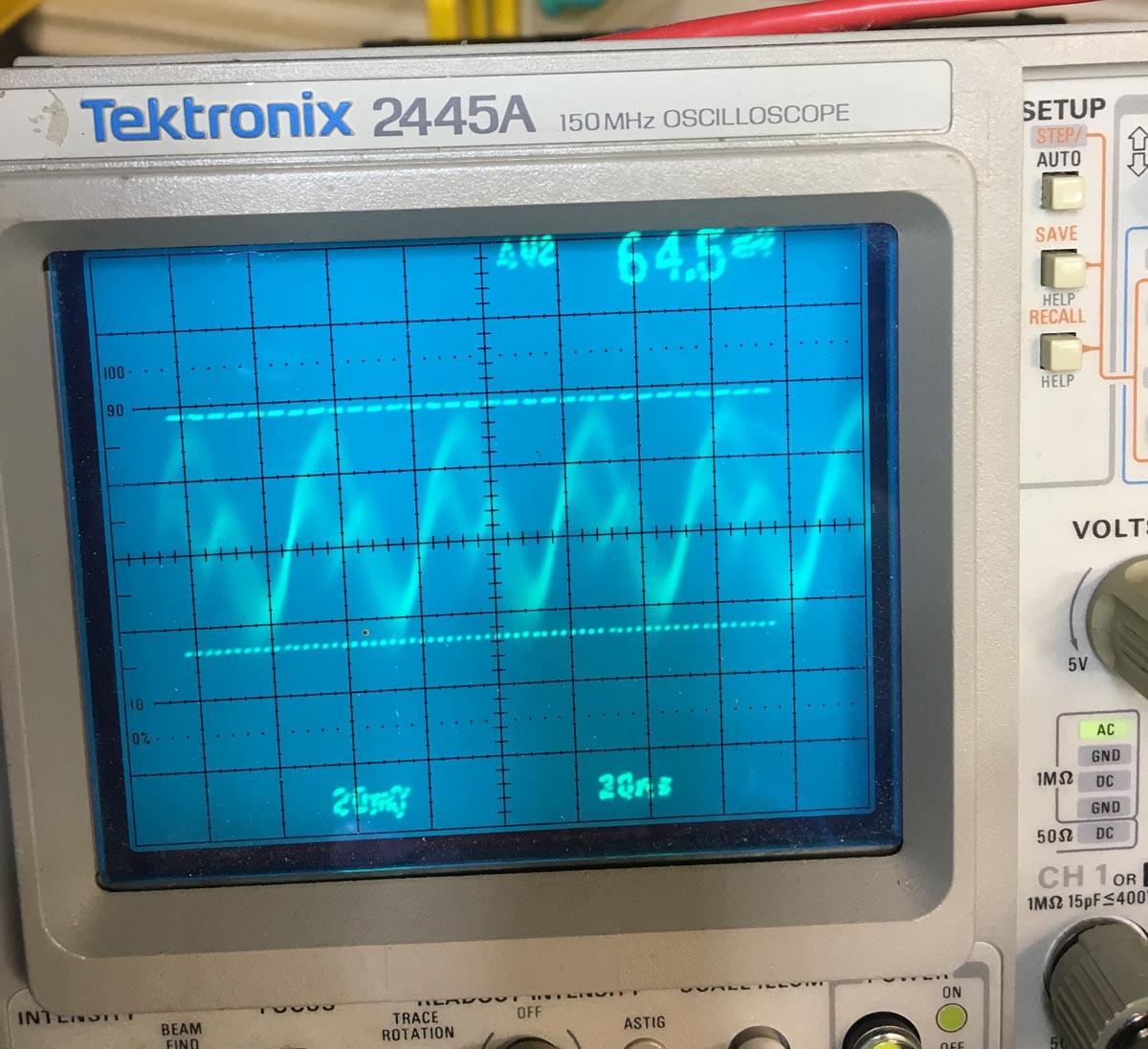
The measured ripple depends a bit on the time scale used; here at 1.8 MHz and full power, still near B100, I see this


but at a slower time base also this


the reading depends anyway on the probe position, I think there is some RF noise picked up there.


Measuring near the DC/DC converter, on DB14, I sometimes see some jumps in the voltage, at low power and at full power, does not make much difference:


but a similar behavior I see also on the other DC/DC converters, so I guess it might be a "feature" of the converter.

Finally, the regulation seen with a two-tone test, still at full power at 1.8 MHz on DB14, seems not too bad


73 de Claudio, IN3OTD / DK1CG


in3otd

unread,
Sep 16, 2017, 7:50:32 AM9/16/17
to Hermes-Lite
On Saturday, September 16, 2017 at 9:25:48 AM UTC+2, in3otd wrote:
Measuring near the DC/DC converter, on DB14, I sometimes see some jumps in the voltage, at low power and at full power, does not make much difference:

I've checked on the H-Lv2b2, I see the same voltage jumps on the 1.2 V and 3.3 V outputs only just after power up with a "cold" board, they disappear after a few seconds. Powering down and up again I no longer see them.
On the VPA supply they are always present instead, I don't remembering having noticed that before.
I'm wondering whether the converter control loop is somewhat unstable and changing the 4.7 nF cap on the voltage divider could help.

Alan Hopper

unread,
Sep 17, 2017, 3:29:10 AM9/17/17
to Hermes-Lite
Claudio, Taka, Steve,
thanks for all the help, my multimeter won't measure r123 but I've confirmed the current measurement is fine with a resistor from t3 centre tap to ground.  The main power supply is fine.  I removed t3 and made one with the output connected direct to the load, this made no difference.  So I guess the vpa supply is faulty.  I think I noticed the distortion in my very first tests before my dummy load broke so I don't think the open circuit testing can be blamed.  Hopefully I'll get some time today to look further.

73 Alan M0NNB 

Steve Haynal

unread,
Sep 19, 2017, 12:49:27 AM9/19/17
to Hermes-Lite
Hi Alan,

I've just measured full power output at 3.8 MHz on my beta3. When I look at the signal into a dummy load with my scope, I see what you might be calling distortion or a bit of "flat topping" of the sine wave. But this is just the presence of harmonics. Since 3.8 MHz is a relatively low frequency, my scope will pick up more harmonics and push the sine wave towards a square wave. If I put a QRP Labs 80M LPF between the HL2 and the dummy load, the signal on my scope now looks like a pure sine wave. I've include spectrum plots for with and without a filter and you can see the difference in the harmonics. Sorry, no easy screen capture of my scope, but I think your Vpa is fine and the distortion you see is expected.

When I measure Vpa I do see a ~330mvpp signal on my scope. It is the second harmonic at 7.6MHz. I see this on both my beta2 and beta3. As Claudio said, there may just be some RF pickup from the scope probes. I am not very worried about this given the spectrum output is clean after filtering.

73,

Steve
KF7O

No filter:


With Filter:

Steve Haynal

unread,
Sep 19, 2017, 12:50:32 AM9/19/17
to Hermes-Lite
Hi Claudio,

I noticed these same jumps on the 8V supply of my beta3. I will experiment with the converter control loop. Please let me know if you discover anything.

73,

Steve
KF7O

Alan Hopper

unread,
Sep 19, 2017, 3:29:51 AM9/19/17
to Hermes-Lite
Steve, 
thanks for that, I was mainly concerned that my board appeared to be behaving differently to others. 

It is still odd that Claudio does not see the same. If I measure at db14 with a sprung earth probe I see a good clean vpa  there, if I use a normal earth clip I see a big ripple.  At b100 I see the same as you however I arrange the earth.  As I go up in frequency the ripple reaches a peak at 3.8MHz , drops off then increases again.  It makes sense to me that it is at 2f as that is the demand on vpa. At 3.8MHz it is in anti phase with the pa output, at higher frequencies it starts to lag, this ties up with the distortion I see on the output.

I did add 2 1.0uf caps on top of  which ever of c144-c147 are closest to t3 just in case the wrong value had been fitted, this made only a marginal improvement so I guess they are correct.  Whilst I'm able to get a clean enough 5W+ output, I'm still suspicious something is not quite right by the fact that increasing vpa improved things.  Equally I'm happy to believe it is all just naive rf expectation and measurement on my behalf:)

73 Alan M0NNB

in3otd

unread,
Sep 19, 2017, 4:13:41 PM9/19/17
to Hermes-Lite
Hello Alan,
I also used a spring ground clip for the measurements, place like this


I've remeasured the ripple/noise there to double check and I get the same results, maybe even a little less.

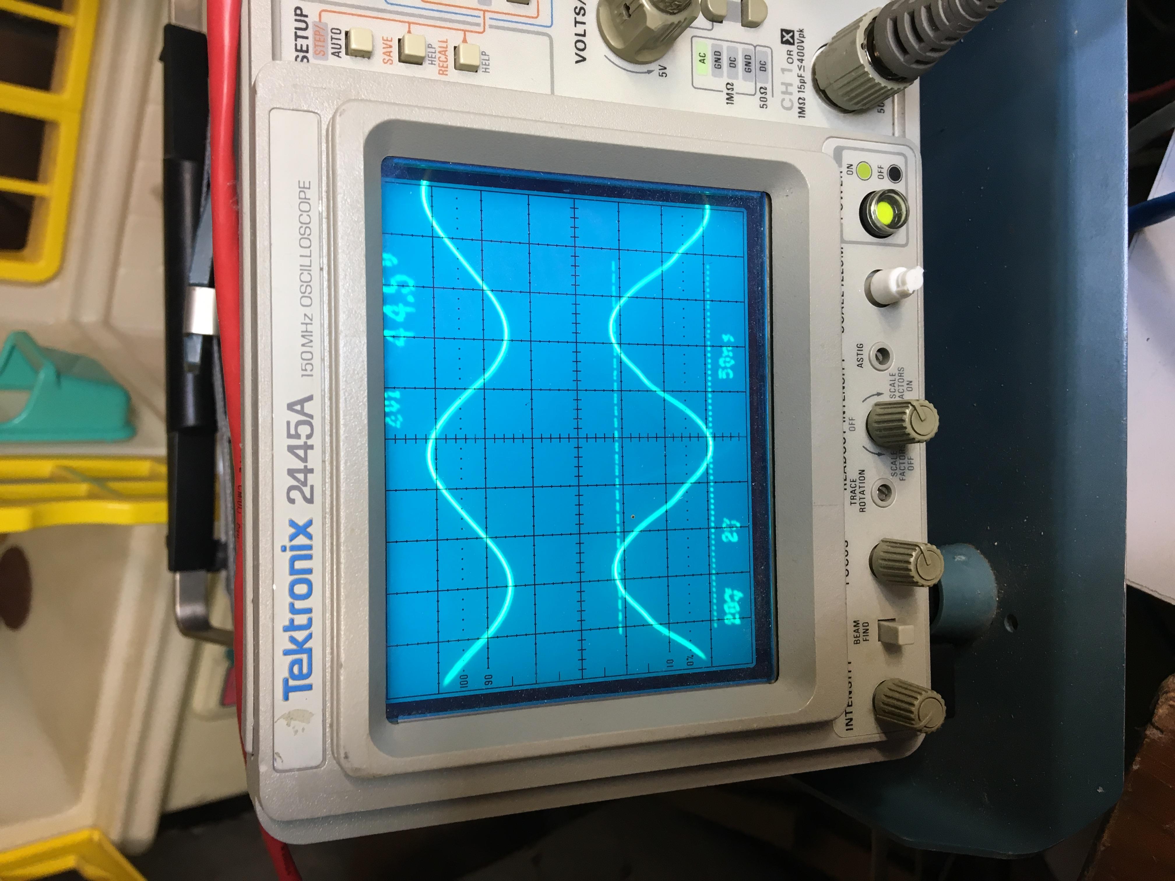
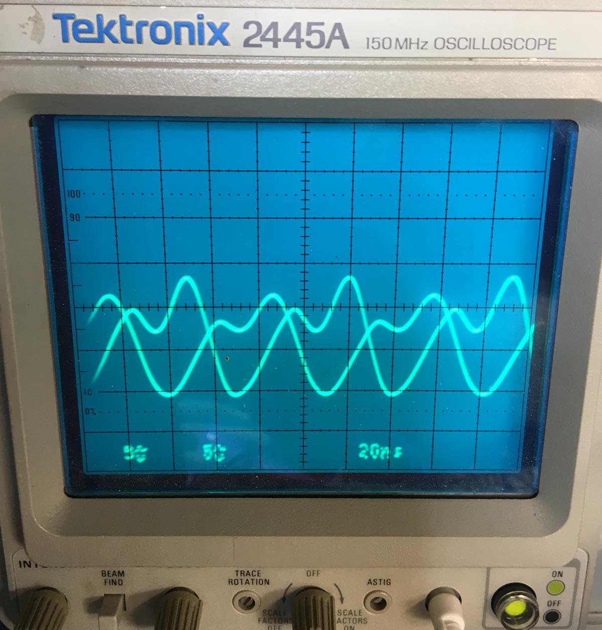
The measurements above were done at 1.8 MHz; as you saw, at 3.8 MHz the ripple on the Vpa supply increases and with the TX at this frequency, I see about 200 mV peak-to-peak near B100:


Note that 3.8 MHz is more or less where the 2nd harmonic has a maximum also(see bottom graph here); it was roughly the same also in the H-Lv2b2.


The waveform on the LDMOS drains looks slightly flattened at the top, so this may be similar to what you see also:


73 de Claudio, IN3OTD / DK1CG

Alan Hopper

unread,
Sep 19, 2017, 4:55:20 PM9/19/17
to Hermes-Lite
Claudio,
thanks for that, I'm now happy that what I see is normal and hence my attempts to fix are allowed to fail.  It has been fun trying to understand this,  out of interest do you have an explanation for the 3.8Mhz peak, is the vpa ripple the cause or  just a side effect of something else?
73 Alan M0NNB

in3otd

unread,
Sep 20, 2017, 2:24:17 AM9/20/17
to Hermes-Lite
Hello Alan,
I'm not sure but I think the ripple peak at 3.8 MHz could be due to the power supply decoupling network having an impedance peak there, due to interactions of the bypass caps with the inductive output impedance of the DC/DC or the inductance of the supply trace. If this is the case moving one of the 22 uF filtering caps near T3 could help moving the peak and reducing its magnitude.


73 de Claudio, IN3OTD / DK1CG

Alan Hopper

unread,
Sep 20, 2017, 4:13:17 AM9/20/17
to Hermes-Lite
Hi Claudio,
out of curiosity I put a 10uf cap directly across t3 pins 2&4, this greatly reduced the ripple measured at b100 and it does not vary significantly with frequency. Once I have the correct value resistor I'll put vpa back to 8V and see if it has helped. From memory the output looks a little cleaner but I would not swear to it.
73 Alan M0NNB

Steve Haynal

unread,
Sep 20, 2017, 11:36:20 PM9/20/17
to Hermes-Lite
Hi Alan and Claudio,

I will try to move one of the 22uF capacitors close to T3. Thanks!

73,

Steve
KF7O

Jack Generaux

unread,
Sep 22, 2017, 4:32:37 PM9/22/17
to Hermes-Lite
I am still chasing residuals of my lightning strike issues.   I have replaced the finals, rewound T3 with teflon, and replaced the caps, but the wave forms are not as clean as before the lightning.  The attached 4 photos show DB20 and the output at 5 watts on 80, 40, 20, and 15 meters.  10 meters was fairly clean but I didn't get a photo.  The bias setting were originally both at the same value (229 if I remember right) but are now different bias 0 is 238 and bias 1 is 231 for 100 mA on each transistor measures at the center tap of T3.  The waveforms look OK after LPF filters.  Any thoughts or suggestions?   Receive and low power seems about the same as before the lightning.

Jack (W0FNQ)
15meter.JPG
20meter.JPG
40meter.JPG
80meter.JPG

Takashi K

unread,
Sep 23, 2017, 5:24:58 AM9/23/17
to Hermes-Lite
Hi Alan,

I have checked the effect of additional 10uF between T3 Pin2 and Pin4.

73, Taka  ji1udd
Effect of additional 10uF between T3 Pin2 and Pin4.pdf

Alan Hopper

unread,
Sep 23, 2017, 6:35:24 AM9/23/17
to Hermes-Lite
Hi Taka,
thanks, that looks very similar to the result I see. The only reason for the 10uf value is that it was all I had!
73 Alan M0NNB

Steve Haynal

unread,
Sep 24, 2017, 2:03:10 AM9/24/17
to Hermes-Lite
Hi Jack,

How clean does Vpa look now? Is one of the PA transistors runing any hotter than the other? Do the input signals for both PA transistors measured at B99 and B106 look roughly the same shape and amplitude? (I am wondering if one of the PE4259 devices is damaged.) Do the signals on the drain of each transistor look roughly the same shape and amplitude too?

The bias values and difference in settings is okay. Mine are like that.

73,

Steve
KF7O

Steve Haynal

unread,
Sep 24, 2017, 2:05:02 AM9/24/17
to Hermes-Lite
Hi Taka and Alan,

What capacitors did you test with? Were they small package (0805) surface mount? Other capacitors may have lower ESR and I want to be sure the situation is improved with a 0805 device. I may switch to a 10uF 1206 device that is used elsewhere in the power supply.

73,

Steve
KF7O

Alan Hopper

unread,
Sep 24, 2017, 2:20:39 AM9/24/17
to Hermes-Lite
Hi Steve,
I used a 1206 Y5V capacitor, as I said, I have no reason the believe 10uF is optimal.
73 Alan M0NNB

Takashi K

unread,
Sep 24, 2017, 4:28:39 AM9/24/17
to Hermes-Lite
Hi Steve,

I used GRM219R61E106KA12D that was on hand. but 50V grade one might be better. 

73, Taka  ji1udd

Jack Generaux

unread,
Sep 24, 2017, 11:42:46 AM9/24/17
to Hermes-Lite
Steve,  

I followed through with your suggestions.  The attached photos show the various waveforms on 20 meters (the worst case.)  Vpa shows a little over 60 mV noise whick doesn't seem too excessive to me.  The PA transistors are both running quite cool -- I can hold my finger on them just detecting a slight warmth at 5 watts.  The input signals to each transistor look very close ( I forgot to take that photo) and the waveforms before and after the PE4259 show a slight loss and a little phase shift.  Both PE4259 show the same. The drains look similar but one magnitude is slightly higher -- I played with the bias a bit but could improve the waveform.  I double checked the values of R92 and R99 and had previously replaced b97 and b105.  I may be chasing a wil-o-wisp in that putting the LPF cleans up the signal.

Jack
BfrAftPE4259.jpg
Vpa.jpg
With LPF.jpg
Drains.jpg

Steve Haynal

unread,
Sep 27, 2017, 12:05:41 AM9/27/17
to Hermes-Lite
Hi Jack,

If you have a spectrum analyzer, you can check your unfiltered emissions to see how close they are to those reported by Claudio here. If they are similar, than I wouldn't worry about them.

73,

Steve
KF7O

Steve Haynal

unread,
Sep 27, 2017, 12:06:43 AM9/27/17
to Hermes-Lite
Hi Taka and Alan,

Thanks for the feedback. I will see about using the larger 1206 package. We already have 10uF high voltage in that package used in the power supply.

73,

Steve
KF7O
Reply all
Reply to author
Forward
0 new messages