Skip to first unread message

Steve Cousins
Feb 21, 2023, 11:21:28 AM2/21/23
to retro-comp
I've started to put together the various suggestions and contributions for the RCBus specification. See attached.
There is a long way to go but feedback would be appreciated.
One fundamental issue I'm having trouble with is this: If you want to design a 6502 CPU module you have a choice to make about interfacing to the backplane. Do you try to generate Z80 compatible signals so it is compatible with existing RC2014 modules, do you just support 68xx bus signals so it will only work with other modules implimeting 68xx signals, or do you provide both sets of signals to the backplane for greatest compatibility.
If you support Z80 style signals the 6502 CPU module will still not be compatible with all existing RC2014 modules. For example, the 6502 memory map requires ROM at the top of memory not the bottom, and also a space for I/O needs to be mapped into memory. That sounds like a big issue, but actually not all RC2014 modules can be used at the same time. Compatibility will always have its limitations. So perhaps this is a red herring.
In any event, the problem I'm having is how to specify what is and isn't required for compatibility. Should the RCBus-68xx specification only include 68xx bus signals or should it include the standard Z80 signals as well? In my mind, if the CPU module only supports 68xx signals then it is only compatible with the 68xx sub-set of RCBus. If it supports only Z80 signals then it is only compatible with the RCBus-Z80 sub-set. If it supports both sets then it is compatible with bith sub-sets of the RCBus spec. This suggests the RCBus-68xx spec should only include signals relevant to the 68xx. But given that there will likely still be significant compatibility issues, is the the right approach?
The alternative thinking I have is the core bus specification should include as many signals as possible even though some will not be relevant to a specific modules (rather like it is now with some RC2014 modules) or to a class of modules such as those using 68xx style signals. Using this approach only the few special signals that share pins with other signals need to be highlighted in specific sub-sets of the spec.
I'd appreciate thoughts on this issue.
Steve

Alan Cox
Feb 21, 2023, 11:58:44 AM2/21/23
to Steve Cousins, retro-comp
On Tue, 21 Feb 2023 at 16:21, Steve Cousins <steve...@gmail.com> wrote:
> One fundamental issue I'm having trouble with is this: If you want to design a 6502 CPU module you have a choice to make about interfacing to the backplane. Do you try to generate Z80 compatible signals so it is compatible with existing RC2014 modules, do you just support 68xx bus signals so it will only work with other modules implimeting 68xx signals, or do you provide both sets of signals to the backplane for greatest compatibility.
You generate the Z80 style signals. If you didn't want to generate the
> One fundamental issue I'm having trouble with is this: If you want to design a 6502 CPU module you have a choice to make about interfacing to the backplane. Do you try to generate Z80 compatible signals so it is compatible with existing RC2014 modules, do you just support 68xx bus signals so it will only work with other modules implimeting 68xx signals, or do you provide both sets of signals to the backplane for greatest compatibility.
Z80 signals you'd use one of the other bus designs for a Motorola bus.
All the current "other" CPU cards from 1802 to Z8 take this approach.
I think of it as analogous to S100 / IEE696 in this respect, except
it's a lot simpler and doesn't require a PSU of similar size and power
consumption to a small microwave oven.
> If you support Z80 style signals the 6502 CPU module will still not be compatible with all existing RC2014 modules. For example, the 6502 memory map requires ROM at the top of memory not the bottom, and also a space for I/O needs to be mapped into memory. That sounds like a big issue, but actually not all RC2014 modules can be used at the same time. Compatibility will always have its limitations. So perhaps this is a red herring.
with ROM mapped over the full 64K so just works. The 32K/32K card has
a jumper. The flat cards almost all have a jumper. Only the old paged
ROM board and RAM combo (that nobody uses) doesn't.
For the I/O with a 256 byte map at $FExx you've got the classic 8bit
256 I/O ports so the only things that don't work are cards that use
full 16bit I/O port decoding (very very few: QUART, ZXKey, dual port
RAM interconnect, and Bill's VGA ?). It's also possible to deal with
this by putting an extra latch on the CPU card so you can set the high
byte of IO cycles. I've just never bothered because it's really not
that important.
> In any event, the problem I'm having is how to specify what is and isn't required for compatibility. Should the RCBus-68xx specification only include 68xx bus signals or should it include the standard Z80 signals as well? In my mind, if the CPU module only supports 68xx signals then it is only compatible with the 68xx sub-set of RCBus. If it supports only Z80 signals then it is only compatible with the RCBus-Z80 sub-set. If it supports both sets then it is compatible with bith sub-sets of the RCBus spec. This suggests the RCBus-68xx spec should only include signals relevant to the 68xx. But given that there will likely still be significant compatibility issues, is the the right approach?
extra lines for convenience if you want. If you are running just
Motorola bus devices and don't care about RCbus you'd use a different
bus to begin with.
I see it this way
- RCbus is a bus specification that happens to use Z80 like signals at
TTL logic levels with CMOS logic.
- The point of RCBus is to be able to use RCBus devices
So on that basis the starting point has to be compatibility. The extra
lines are a convenience for a few things, not the norm. In fact I/O
cards intended for 65xx/68xx should try not to use them unless needed
so they are still compatible with Z80, 1802, 68000 whatever.
> The alternative thinking I have is the core bus specification should include as many signals as possible even though some will not be relevant to a specific modules (rather like it is now with some RC2014 modules) or to a class of modules such as those using 68xx style signals. Using this approach only the few special signals that share pins with other signals need to be highlighted in specific sub-sets of the spec.
all the other stuff on it), the classic 40pin and bigger variants
documented as such. I'd prefer the "and this is useful if you run CPU
x" bits to be an addition not a core part of the bus. I'm not sure
they are even properly "RCbus" so much as "and here's a useful
convention on assignment of the user pins"
The base set is probably very small and that may be useful - it's what
VCC/GND/D7-D0/A7-A0/IRQ/IORQ/RD/WR/RESET (and maybe M1) ?
Alan

Jordi Autocet
Feb 21, 2023, 12:02:03 PM2/21/23
to Steve Cousins, retro-comp
Steve,
Sorry for the intrusion. I say this because I have studied it a lot. The 80 pin limit is very small. S100 didn't get away either.
Good luck with the adventure, it's really cool.
Jordi Breu
Missatge de Steve Cousins <steve...@gmail.com> del dia dt., 21 de febr. 2023 a les 17:21:
--
You received this message because you are subscribed to the Google Groups "retro-comp" group.
To unsubscribe from this group and stop receiving emails from it, send an email to retro-comp+...@googlegroups.com.
To view this discussion on the web visit https://groups.google.com/d/msgid/retro-comp/62e3c208-6d6d-41ac-802d-7727b9d97cf6n%40googlegroups.com.
Alan Cox
Feb 21, 2023, 12:25:38 PM2/21/23
to Jordi Autocet, Steve Cousins, retro-comp
RC-6502 is an existing thing and has been for some time. It's an "if I
did RC2014 with 6502 it would look like this" bus but it's not
compatible with RCBus so solves a different problem.
In fact Bill already has RC6502 bus cards...
did RC2014 with 6502 it would look like this" bus but it's not
compatible with RCBus so solves a different problem.
In fact Bill already has RC6502 bus cards...

Tadeusz Pycio
Feb 21, 2023, 12:43:51 PM2/21/23
to retro-comp
I think compatibility of all modules for different architectures is impossible without introducing another layer as Jordi mentioned. Signals, e.g. in 6502 have to be adapted to universal I/O chips, memory anyway, so making them compatible with Z80 standard is a good direction for RCBus. Architecture-specific I/O circuits should work with that architecture on RCBus, with others not necessarily. For example, I don't know if anyone has managed to get a Z80 SIO to work with the 6809. As Alan mentioned, the basic kit is small.
I mentioned earlier that I have a Z80 training kit and there is one MEM_EN signal that is worth putting in RCBus space. Obviously it won't be compatible with existing memory module solutions, but as a prospective solution because it does the trick of injecting code onto the bus. A similar solution has been used in the Z80-MBC2, V20-MBC from J4F. This could be useful, but I assume it will require dedicated modules.
I mentioned earlier that I have a Z80 training kit and there is one MEM_EN signal that is worth putting in RCBus space. Obviously it won't be compatible with existing memory module solutions, but as a prospective solution because it does the trick of injecting code onto the bus. A similar solution has been used in the Z80-MBC2, V20-MBC from J4F. This could be useful, but I assume it will require dedicated modules.
Alan Cox
Feb 21, 2023, 12:57:29 PM2/21/23
to Tadeusz Pycio, retro-comp
I don't believe anyone has ever gotten the classic Zilog peripheral
chips to work with anything but a Z80 or Z180 (and maybe Z280 in 8bit
mode ?). They have magic knowledge of the internal behaviour of the
processor. The later stuff you can (but the later stuff like the Z8530
is instead a pig to nail onto a Z80)
The only cards that don't work with the other processors that I know
of are some of the ACIA boards (because of the way their motorola bus
interfaces are glued to the Z80 bus), the Zilog peripherals and the
cards using 16bit I/O.
The 16bit I/O is doable if wanted, and I think Phillip got his 8085
generating the signals correctly for the 68B50 to work ?
The other oddments are electrical issues - unbuffered CF with NMOS
devices (affects NMOS Z80 as well) and cards that are naughty with
voltage levels (not shifting 3v3 because they know the CPU is a Z80 so
TTL level high/low)
Alan

Mark T
Feb 21, 2023, 3:18:59 PM2/21/23
to retro-comp
I was thinking PAGE could be renamed RAMEN, as this is its function with the pageable ROM and 64K ram modules. This can also be used in systems without Pageable ROM to provide code injection with RAM disabled.
I was a little confused on first reading of Steve’s document when I saw RCBus-Zx80, until I realised this was for both Z80 and Z180 rather than the old Science of Cambridge machine. Would Z*80 cause more or less confusion?
I think supply voltage should be defined as 5v, but if someone feels the need to build a 3.3v system they should make that very clear in their documents. Regulating down to 3.3v is very easy local on modules for supply to sdcards etc.
Signal levels on the bus should meet TTL input levels for compatibility with nmos on some older devices, with 5v tolerant inputs. I think cmos input loading should be recommended, not proscribed. Output levels should be recommended as 5v HCT outputs, again not mandated.
Mark T
Feb 21, 2023, 3:27:04 PM2/21/23
to retro-comp
Sorry, that should be 5v tolerant inputs and outputs, for cases where a 3.3v device is driving ttl compliant outputs onto the bus.

Ed Porter
Feb 21, 2023, 5:46:39 PM2/21/23
to retro...@googlegroups.com
On 21/02/2023 18:56, Alan Cox wrote:
> I don't believe anyone has ever gotten the classic Zilog peripheral
> chips to work with anything but a Z80 or Z180 (and maybe Z280 in 8bit
> mode ?). They have magic knowledge of the internal behaviour of the
> processor. The later stuff you can (but the later stuff like the Z8530
> is instead a pig to nail onto a Z80)
Pages 198-205 of "THE Z8000 MICROPROCESSOR A Design Handbook" by Bradly
> I don't believe anyone has ever gotten the classic Zilog peripheral
> chips to work with anything but a Z80 or Z180 (and maybe Z280 in 8bit
> mode ?). They have magic knowledge of the internal behaviour of the
> processor. The later stuff you can (but the later stuff like the Z8530
> is instead a pig to nail onto a Z80)
K Fawcett shows some TTL glue to attach Z80 peripherals to the Z8000
bus, including an I/O port to generate the ED4D RETI sequence at the end
of an interrupt service routine. It does look like more trouble than
it's worth.
https://archive.org/details/bitsavers_zilogz8000andbook1982_15357800/page/n207/mode/2up
-ed
Tadeusz Pycio
Feb 24, 2023, 2:42:34 PM2/24/23
to retro-comp
I would like to clarify the meaning of pin 60 - PAGE (although a better name would be RAM_EN). The High state enables RAM (all or part of it), the Low state disables its activity. This will allow existing modules using the PAGE signal to continue to operate (to disable ROM and enable RAM instead), and newly created modules will be able to temporarily disable all RAM in order to inject code onto the data bus by modules running on the Z80-MBC2 concept.
We still do not have assigned pins for the DMA service request signals. My suggestion was to use pins 78 (DREQ1) and 79 (DREQ2), but if others see the need to add DACK/EOP in addition to these signals it is worth considering another location (pins 45-48 ?).
We still do not have assigned pins for the DMA service request signals. My suggestion was to use pins 78 (DREQ1) and 79 (DREQ2), but if others see the need to add DACK/EOP in addition to these signals it is worth considering another location (pins 45-48 ?).
Steve Cousins
Feb 24, 2023, 2:57:41 PM2/24/23
to retro-comp
I've updated the RCBus Specification to reflect the views above. This is mainly seen in the table of pin assignments where most of the traditional RC2014 pins are clearly shown as common to all processor types.
I've also padded it out a bit more with pin descriptions and connector details.
If there is anything you feel is wrong, not well presented, or missing please point it out. There are unanswered questions in the "Unresolved issues and notes" section.
Steve
Alan Cox
Feb 24, 2023, 5:00:59 PM2/24/23
to Steve Cousins, retro-comp
You have an appended where I think you mean appendix.
On the high address lines wiring them to 0v or 5v is bad if a wrong
card combination is used. It's also a problem because cards may not
even have those pins present. Perhaps
Current RC2014 systems use either 16bit or 20bit addressing and do not
support using a memory card that has more address lines than the
processor card. If a memory card is intended to be usable with
processor cards that have less address pins it should have pull up or
pull down resistors on the upper address lines.
ie
- it's optional
- nobody does it right now
- use resistors so it doesn't go boom if an error is made
Steve Cousins
Feb 27, 2023, 5:28:24 PM2/27/23
to retro-comp
I've made further progress on the RCBus specification. Most of what I think is necessary is now in place although use with more processor types need to be added - anyone???
It would be helpful if more members of the community could share their thoughts on the RCBus specification. It will only succeed if it is acceptable to most people here.
I'm sure there are lots of improvements that need to be made so feedback your thoughts please.
Steve
Mark T
Feb 27, 2023, 8:15:34 PM2/27/23
to retro-comp
I think I would prefer BAI/BAO at the same end of the bus as IEI and IEO. Partly because then Z80 is allocated existing user pins and leave n41 to n48 for functions not used by z80 processors, and maybe not for any of the 8 bit micros. I think that also works better with the option of IEI/IEO and BAI/BAO to be via link wires between modules and only having those at one end of the modules rather than opposite ends. Its likely that a module using BAI/BAO would also need IEI/IEO.
I have considered using RCBus for INS8060 or INS8073 to reuse modules with these two processors. I think these have a close enough match to z80 interface to not need their own bus variant. I expect SIn and Sout to rx and tx. Sense A to Int. Sense B and flags to user pins. Possibly using refresh for NADS, though I think this could be limited to the processor module. BAI/BAO would be reused for NENIN and NENOUT.
Alan Cox
Feb 27, 2023, 8:31:51 PM2/27/23
to Mark T, retro-comp
> I have considered using RCBus for INS8060 or INS8073 to reuse modules with these two processors. I think these have a close enough match to z80 interface to not need their own bus variant. I expect SIn and Sout to rx and tx. Sense A to Int. Sense B and flags to user pins. Possibly using refresh for NADS, though I think this could be limited to the processor module. BAI/BAO would be reused for NENIN and NENOUT.
That was my conclusion some time ago - I've just never found a source
of INS807x parts at a sane price to bother turning the PCB design into
a board. Passing NENIN/NENOUT would make sense. I just had those as
flying leads so you could run multi-processor if you could afford to
spend $150 a shot on possibly dodgy remarked parts.
Alan

Brad Hines
Feb 27, 2023, 11:38:00 PM2/27/23
to Steve Cousins, retro-comp
Hi All,
I've been enjoying the RCBus discussion. Something just occurred to me last night that I thought I should mention, which is that I'm worried about the name "RCBus". I'll leave it to all of you to decide what to do with it or about it.
The issue is the possibility of brand confusion between RC2014 and RCBus. As someone who has just recently discovered RC2014 and Z50Bus and all of the above, I can say that it took me a couple of days to sift through everything that was out there and figure out what the situation was.
One of the questions that one has to resolve as you peel all this back is "which came first, which is derived from which", and so on.
I think if I had been coming into it and had seen both RCBus and RC2014, I would have been a bit confused. To a newbie, the assumption would be that they are related, probably branches off the same tree. And to a degree they are, but at the same time, our new RCBus is intended to be a fresh start, with different parentage. And it definitely would have been confusing figuring out which is more recent.
To some degree, maybe we want the similarity of names for what that communicates. But that's where one can run into trouble with trademarks. Having dealt with this in my businesses a bit over the years, I suspect that we will have an issue with RCBus infringing on the RC2014 trademark.
Why? The reason is that the way the trademark office looks at these things (at least in the U.S. - I am admittedly slightly out on a limb with extrapolating this to the UK) is, "What are the chances that a consumer will confuse the protected brand with the competing brand?" If a realistic chance for confusion is present, the new mark is infringing.
If the owner of the RC2014 trademark seeks to enjoin us from calling our bus RCBus, I would give high odds that he would succeed.
So that was the thought I thought I'd share. Feels like it might be good to pick a different name.
Brad
--
You received this message because you are subscribed to the Google Groups "retro-comp" group.
To unsubscribe from this group and stop receiving emails from it, send an email to retro-comp+...@googlegroups.com.
To view this discussion on the web visit https://groups.google.com/d/msgid/retro-comp/66b4c474-b868-4027-baac-cc046531900dn%40googlegroups.com.
Brad Hines
Brade...@gmail.com
Brade...@gmail.com
Tadeusz Pycio
Feb 28, 2023, 4:59:36 AM2/28/23
to retro-comp
Hi Brad,
I think you have misread our intentions, RCBus is meant to unite not divide. If someone confuses RC2014 with RCBus it will not be a mistake, any RC2014 module will work on RCBus. This is not an attempt to build a new standard (a very tempting proposition) or to build a new brand. We want to standardise the naming and standardise the missing signals on the bus. If we don't do this, everyone will call it according to their own vision, use the free pins in the way most convenient for themselves. This state of affairs will create more confusion for new users. One final point, Spencer did not object to using a different name.
If the idea of RCBus were to be about something new, the bus would certainly change. I've only designed 15 modules, so I already know the disadvantages of this arrangement of signals on the bus. I have old-fashioned PCB design principles, I believe that power lines should be a minimum of 18 mils wide and I do not tolerate vias for these lines, and placing them on the bus in the middle leads to circus tricks to keep these principles for a double-sided PCB. This would certainly be the first thing I would change. Here no one wants to change it to be consistent with existing solutions.
@All
I have a suggestion that further ideas should already be concretised - name/meaning/no. pin.
We should have already released the first version of the RCBus specification, Steve has done a lot of work and we are still moving on general outlines of what should be in there. Maybe try to finish the bus for Z*80, 6800 and 6502 and then focus on developing for other architectures. For example, I don't know what signals we want to have for 68000 support, not counting byte select signals. Is that all this processor needs to run on the RCBus?

TonyD
Feb 28, 2023, 5:01:56 AM2/28/23
to retro-comp
Hi All
I've been following this discussion with great interest.
A couple of discussion points I would like to add is that of:
- Board dimensions
- External Connector positions
best regards
Tony
I've been following this discussion with great interest.
A couple of discussion points I would like to add is that of:
- Board dimensions
- External Connector positions
Thank you all for such a good and open discussion.
Tony

Karl Albert Brokstad
Feb 28, 2023, 5:15:59 AM2/28/23
to retro-comp
Good discussion. At last, we may agree on a standard.
My suggestion is that the name RCbus covers the general standard, and provision for different sub-standards like 40 and 80 pins connectors, giving RC40bus and RC80bus respectively. This a naming convention I have used on my designs.
Karl
Steve Cousins
Feb 28, 2023, 5:39:02 AM2/28/23
to retro-comp
I think the RCBus specification should suggest board dimensions and connector positions but not try to limit designers to them.
There are two common RC2014 module sizes in Spencer's range: standard and low profile. I think both of these should be suggested in the spec.
The low profile modules are the full 40 pins long, whilst the standard modules are 39 pins long. I'd like to start making my standard modules 40 pins long. Spencer's module template for standard size modules also places the bus connector slightly off centre which seems odd. I would like to suggest anyone making modules 40 pins long should centre the bus connector, as Spencer has done with his low profile modules.
In addition I'd like to add a larger module size to allow more highly integrated designs and to allow nicely spaced components and useful screenprint. I very much like Spencer's single function modules as it has a valid educational aspect to it and, well, it is just nice. However, once you are over that part of the learning curve it is desirable to have the option of fewer modules. Less soldering, greater reliability. Some people building kits have never done any soldering before so it is important to me to be able to space components out etc. to make the assembly process less intimidating for inexperienced makers. I don't really like the look of modules greater than about 3 inches (75mm) tall but I think I would still like to suggest a module size nearer 4 inches (100mm) tall.
Steve
Alan Cox
Feb 28, 2023, 6:22:32 AM2/28/23
to Brad Hines, Steve Cousins, retro-comp
> To some degree, maybe we want the similarity of names for what that communicates. But that's where one can run into trouble with trademarks. Having dealt with this in my businesses a bit over the years, I suspect that we will have an issue with RCBus infringing on the RC2014 trademark.
To quote Spencer from the RC2014 list
"RCBus or RC80 Bus sound good to me. It takes the essence of what the
bus is without limiting it by what the RC2014 natively supports."
So we should be good on that front. It's not really about lawyers
anyway it was a polite request. Either way Spencer's quote I think
probably counts for estoppel ;)
Alan
Brad Hines
Feb 28, 2023, 4:37:19 PM2/28/23
to Tadeusz Pycio, retro-comp
Hi Tadeusz,
To be clear, my point wasn't about intent, it was about legal jeopardy. I think the goals you suggest are good ones.
I do still think confusion is a concern. The use case is a newbie trying to decide on the backplane for his or her system. Does the term inform which kind of backplane is recommended for a new system, or does it muddy the water?
In my case, when I got started with RCxx, I had to decide what kind of backplane modules to buy. RC2014, RC40, RC80, Z50Bus? There was a bit of alphabet soup, and no clear indication of which was the latest. Once RCBus is complete and available, then a newbie would likely want to buy a RCBus backplane. It would be a sadness for someone to buy a RC2014 backplane and then realize that the slick new card that they want is only available for the newer bus. If our new bus were called "RC2023", for example, then it would clearly inform the user. But that would likley run afoul of trademarks even more than RCBus.
As far as legal, it may be okay given what you said. I'm not sure who Spencer is - if he's the owner of the RC2014 trademark and has blessed the use of the term RCBus, then I'm sure it's fine. If not, we could end up in a situation where we are forced to change the name in a year or two or three.
It may be that RCBus is the best term. To me the ideal term would capture the heritage but also let you know which came first. Something like "RCNext"? I'll be happy with whatever is chosen; it doesn't really affect me, just thinking about new folks entering the domain.
Brad
--
You received this message because you are subscribed to the Google Groups "retro-comp" group.
To unsubscribe from this group and stop receiving emails from it, send an email to retro-comp+...@googlegroups.com.
To view this discussion on the web visit https://groups.google.com/d/msgid/retro-comp/29a9dea7-9b2c-4de4-9554-062133ebacf7n%40googlegroups.com.
Brad Hines
Brade...@gmail.com
Brade...@gmail.com
Brad Hines
Feb 28, 2023, 4:45:13 PM2/28/23
to Alan Cox, Steve Cousins, retro-comp
Just saw this.
I guess Spencer must be the trademark holder. Yes, I agree that that puts us in the clear.
Brad Hines
Brade...@gmail.com
Brade...@gmail.com
Tadeusz Pycio
Feb 28, 2023, 5:23:41 PM2/28/23
to retro-comp
Hi Brad,
You are quite right about the choice of backplane, but that is the only risk of error that can be made. I think the name RCBus will make it unnecessary to do an analysis of what RC2014, RC80, RC40 are, because for this environment they will become a homogeneous name. Of course, the modules that will be created on the new specification will not be able to make the most of their capabilities on the RC2014 backplane, but it will be possible to run them, without interrupt priority cascade, additional interrupt lines or be handled by DMA. The vast majority of kits can cope without these enhancements. I think we'll also be waiting a long time on the new standard for practical implementation of DMA usage - I only started needing interrupt priority cascade when I wanted to use RTM-Z80, and additional interrupt lines when building CP/Net, so these are not common used applications.
brade...@gmail.com
Feb 28, 2023, 6:21:14 PM2/28/23
to Tadeusz Pycio, retro-comp
Those sound like well-reasoned arguments to me. Thanks for the dialog.
--
You received this message because you are subscribed to the Google Groups "retro-comp" group.
To unsubscribe from this group and stop receiving emails from it, send an email to retro-comp+...@googlegroups.com.
To view this discussion on the web visit https://groups.google.com/d/msgid/retro-comp/c169c764-d9c5-4cf6-9fa0-49d41a6c19bdn%40googlegroups.com.

Wayne Warthen
Feb 28, 2023, 10:19:11 PM2/28/23
to Steve Cousins, retro-comp
On Tue, Feb 28, 2023 at 2:39 AM Steve Cousins <steve...@gmail.com> wrote:
The low profile modules are the full 40 pins long, whilst the standard modules are 39 pins long. I'd like to start making my standard modules 40 pins long. Spencer's module template for standard size modules also places the bus connector slightly off centre which seems odd. I would like to suggest anyone making modules 40 pins long should centre the bus connector, as Spencer has done with his low profile modules.
I don't have a lot of input on the RCBus specifications, but I strongly agree with a couple things Steve suggests here.
Yes, please deprecate 39 pin connectors. Far too easy to misplug them. Yes, please center the bus connector. It simply makes no sense for it to be offset. Since Spencer has already made those adjustments in his latest form factor, it does not seem like a problem to standardize that way.
Thanks,
Wayne
Mark T
Feb 28, 2023, 11:48:18 PM2/28/23
to retro-comp
Maybe keep the pin1 end of the module the same profile relative to pin 1, but extend the pin40 end of the module to centre the module on the 40/80 pin connector. I think this would avoid a random staggered apearance to the system, at least at one end of the bus.
I think Jlcpcb allows 102mm with before the price starts to increase, unless they changed that recently. Last I checked you could used 102.4mm as they round to nearest mm for pricing. This does have the disadvantage of locking in to a single supplier, unless any other manufacturers have started to support this.

Sergey Kiselev
Mar 1, 2023, 12:09:35 AM3/1/23
to retro-comp
Not sure if it is documented anywhere or was mentioned before. I'd recommend having connectors that normally go to external devices on the right side of the board, connectors that go to the internal devices (e.g. floppy) on the top, and indicators (and perhaps buttons/switches or configuration jumpers) on the left, more narrow side.
Tadeusz Pycio
Mar 1, 2023, 2:44:57 AM3/1/23
to retro-comp
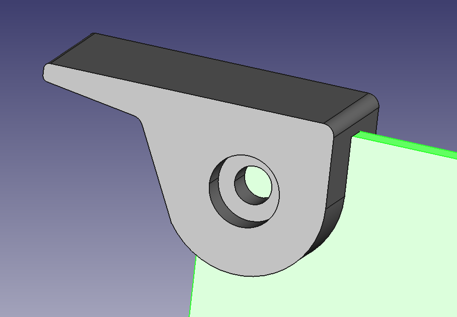
A frequently raised issue is the difficulty of removing modules from the slots. It might be worth thinking about suitable holes in the PCB and trying to design ejectors to make this task easier. It would have to be a simple design that allows such a component to be made on a 3d printer. I don't know if there are any ready-made solutions widely available.
TonyD
Mar 1, 2023, 5:10:59 AM3/1/23
to retro-comp
On Wednesday, 1 March 2023 at 07:44:57 UTC Tadeusz Pycio wrote:
A frequently raised issue is the difficulty of removing modules from the slots. It might be worth thinking about suitable holes in the PCB and trying to design ejectors to make this task easier. It would have to be a simple design that allows such a component to be made on a 3d printer. I don't know if there are any ready-made solutions widely available.
Yes, I agree 40-pin connector cards can be difficult to pull out a backplane.
I've used these types of PCB card ejectors / pulls of other board designs.
https://uk.rs-online.com/web/p/pcb-card-inserters-extractors-ejectors/5073687
https://www.toby.co.uk/pcb-hardware/card-guides-and-pulls/
https://www.essentracomponents.com/en-gb/s/card-ejector
I'm sure there will be 3D printed equivalents
Tony
Tadeusz Pycio
Mar 1, 2023, 8:37:54 AM3/1/23
to retro-comp
I don't know if this is a good idea with the ejector though. The PCBs are small, the edges are often used so there is no room for such facilities. The only idea I have is a rectangular PCB with holes on the top corners and handles in the form of a whistle.
Mark T
Mar 1, 2023, 11:25:13 AM3/1/23
to retro-comp
Maybe someone could design something to fit around 40 or 80 pin female headers on the backplane with levers to push up on the edge of the pcb at each end. No modification to the modules needed, but possibly mounting holes on the backplane if its not a firm fit on the headers. Would a 3d printed part be strong enough?

PauldB
Mar 1, 2023, 5:15:31 PM3/1/23
to retro-comp
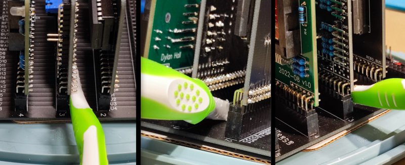
Here's a (very) low-tech method for lifting modules from an RC2014 / RCBus40 / RCBus80 backplane which doesn't require any
modification to current hardware. A KISS solution that works well, most of the time *
The 'tool' is a toothbrush handle with the brush end cut off. Note that the plastic on this handle is of a softer type that doesn't scratch the backplane.
I've made a number of these over time and they work quite well as a lever (among other uses; I usually trim the end of the handle to a flat blade with a knife for poking around electrical things 8) )
* It can be a bit tricky to use if the module to be removed is mounted in the socket on the side of the backplane that has an LED, switch, etc. right next to it.
Paul

Bill Shen
Mar 1, 2023, 5:20:19 PM3/1/23
to retro-comp
I found an angled forceps very effective in prying a board loose.
For board I need to remove frequently, I would place it at the end of the backplane where I can get index and middle fingers of both hands under the 90-degree connector and push board out against my thumbs. It is quick and easy.
Bill
For board I need to remove frequently, I would place it at the end of the backplane where I can get index and middle fingers of both hands under the 90-degree connector and push board out against my thumbs. It is quick and easy.
Bill

Gary S
Mar 1, 2023, 6:07:48 PM3/1/23
to retro-comp
The toothbrush handle is actually allow the way to an idea I am have been thinking of.
In the S100 arena as many others it the lifters being on the removable board, which also entails a frame to work against.
This a bit in reverse, a good motherboard design could have "optional" designed in to act againt the base of the boards inserted. Yes this is actually a development along the idea of the toothbrush handle.
Sorry Steve, maybe we can throw this back onto you to design a suitable compatible motherboard ?? (hehe).
Tadeusz Pycio
Mar 2, 2023, 4:32:20 AM3/2/23
to retro-comp
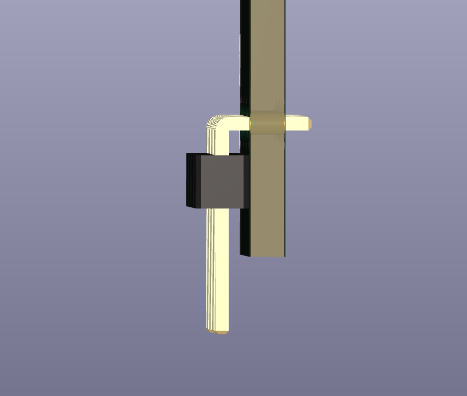
Proposal for dimensioning the standard PCB size of the RCBus module. I have raised the connector so that the plastic part rests on the PCB and increased the size of the whole PCB propionally for the 40 pin connector. In the slot such a module will be 2.54mm taller and 1.6mm longer. The position of the hole has been retained. I don't know if we shouldn't also decrease the bevel to 0.5", not much, but it increases the PCB area. For 40-pin connectors, it would be necessary to use angled asymmetrical connectors in order to maintain an equal distance between modules in the backplane.
Steve Cousins
Mar 2, 2023, 5:35:00 AM3/2/23
to retro-comp
Hi Tadeusz,
I was thinking the same things. The extra space between the bus header and the edge of the PCB could be used to run 5V and GND to the ends of the PCB. This would allow the creation of a power ring around the outer edge of the module, thus reducing the power routing issues we have at the moment. There should also be room to run a track of two in the new space to help with routing.
I think your dimension to the mounting hole (1450.000 mils) might be wrong. Looks like it should be 1400.000 to me.
I'm very keen to move to 4000 mils wide and like the idea of reducing the size of the bevel. I think the rounded corner could be reduced as well, possible to 50 mils. The PCB would still retain the familiar look. Altering the look slightly might help distinguish RCBus modules from RC2014 modules - if that is considered desirable.
I would still like to suggest a larger module size as an option, perhaps as large as 4000x4000 mils.
I doubt this will be a popular idea, but I've also been looking at the cost implications of slightly longer modules, say 4400 mils. For prototyping the cost issue is significant but for production quantities I think the benefits might justify the small extra cost. Going longer would further help with routing power around the bus header. It could also provide an overhang beyond the bus header which would make levering the modules out much easier. One of the things I like about the Z50Bus is the modules are wider than the bus headers. It really helps with extracting modules from the backplane. My thinking is while the PCB may be longer it might not make the overall space required for a module any longer as connectors could be within the outline of the PCB rather than stick out. This would allow prototypes to stay withing the proposed 4000 mils size. Also, the module would still be narrower than the official RC2014 backplanes. Mixing the two sizes would look horrible which might be the biggest reason to avoid the idea.
Steve
Steve Cousins
Mar 2, 2023, 5:41:31 AM3/2/23
to retro-comp
Regarding Mark's suggestion for placing BAI/BAO at the same end as IEI/IEO. There are two reasons I'd rather not do this:
1/ I assume the backplane will have jumpers to make the BAI and BAO pins either direct connections (for non-Z80 uses) or daisy-chained (for advanced Z80 systems). Similarly for IEI/IEO. Trying to put these together at one end will cause space issues. Attached is a rendered image of my latest thinking for an RCBus backplane.
2/ I'd rather use the newly available pins at the other end so as to minimise compatibility issues with the established USER pins. Although, USER5 to 8 have not been used by many designs.
On Tuesday, 28 February 2023 at 01:15:34 UTC Mark T wrote:
I think I would prefer BAI/BAO at the same end of the bus as IEI and IEO. Partly because then Z80 is allocated existing user pins and leave n41 to n48 for functions not used by z80 processors, and maybe not for any of the 8 bit micros. I think that also works better with the option of IEI/IEO and BAI/BAO to be via link wires between modules and only having those at one end of the modules rather than opposite ends. Its likely that a module using BAI/BAO would also need IEI/IEO.
I have considered using RCBus for INS8060 or INS8073 to reuse modules with these two processors. I think these have a close enough match to z80 interface to not need their own bus variant. I expect SIn and Sout to rx and tx. Sense A to Int. Sense B and flags to user pins. Possibly using refresh for NADS, though I think this could be limited to the processor module. BAI/BAO would be reused for NENIN and NENOUT.
Tadeusz Pycio
Mar 2, 2023, 9:17:24 AM3/2/23
to retro-comp
Yes, indeed the hole should be at 1400 mils. I've attached a corrected drawing, with the replacements Steve was talking about. I'm wondering if extending the PCB further on the connector side would eliminate the wobble of the modules, but doing so will make the modules even harder to pull out.
Mark T
Mar 2, 2023, 10:44:07 AM3/2/23
to retro-comp
I prefer the style of 40 pin connecter shown in Tadeusz last post, as this then has the same height as the dual roaw connector, both of these have a more defined mating face with the backplane connectors.
I find extending the board edge behind the connector makes it easier to fit the connectors in a consistent angle on the modules, but probably not a good idea to extend the board past the plastic of the connector. I’m not sure it would make the module harder to remove, but it might make it harder to fit if extra care is not taken when the connector is soldered to the module. The female headers are slightly wider than the plastic carrier of the pin headers.
One issue of changing the board edge is compatibility with standard modules if someone does design a card eject system based on the board edge. One possible solution is to only extend the board edge in the range of pins 8 to 32 or similar, this leaves edges at the same height for card ejectors but provides some extra support fitting the pin headers.
I think we should avoid too many changes to the outline shape, I think only the right edge should be changed to allow 40 pin connectors.
I consider the hole in the board to be optional but some people might consider that useful for additional support.
Tadeusz Pycio
Mar 2, 2023, 11:30:22 AM3/2/23
to retro-comp
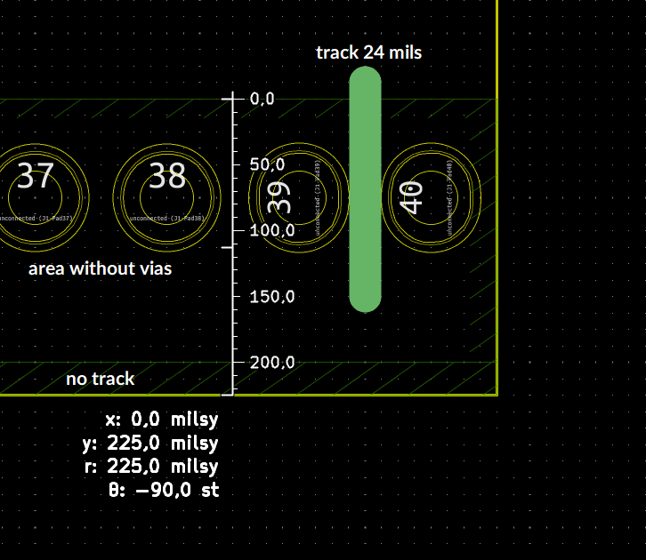
Here are the more specific non-mandatory rules I will follow. The space under the connector will allow for a 24 mils track width after custom pads modification. Nice. :)
Mark T
Mar 2, 2023, 11:55:28 AM3/2/23
to retro-comp
I think you need to allow a little more for alignment between solder mask and tracks to avoid any slight mis-registration allowing bare copper on the edge of a track, which could allow solder shorts if the assembler doesn’t take enough care during soldering.
Tadeusz Pycio
Mar 2, 2023, 12:21:34 PM3/2/23
to retro-comp
I have not given the pads fillings, so perhaps the drawing is misleading. There is actually quite a bit of gap there without violating the DRC rules.
Steve Cousins
Mar 2, 2023, 5:40:06 PM3/2/23
to retro-comp
Attached is an updated version of the RCBus specification, including the latest contributions from Alan.
I've really only pasted in the contributions and have done nothing to remove duplicate information or improve consistency.
Further contributions and feedback welcome.
Steve Cousins
Mar 3, 2023, 5:31:57 AM3/3/23
to retro-comp
The RCBus specification will include suggested or recommended module sizes and shapes. I assume this will take the form of dimensioned drawings. In order to pin this down could we vote on the following:
Question 1: Should we include a module size suggestion of 4"/4000mil/101.6mm long? (that allows space for the full 40/80 pin headers)
Question 2: Should we include a module size suggestion of 3.9"/3900mil/99mm long? (for those who want consistency with RC2014 39-pin long modules and for a wider choice of low cost PCB manufacturers)
Question 3: Should we include a module size suggestion similiar to the RC2014 Classic 2 low profile modules? (4"/4000mil/101.6mm long by 1"/1000mil/25.4mm high)
Question 4: Should we include a larger module size, perhaps 4"/4000mil/101.6mm square? (particular well suited to prototyping but also allows greater functionality or nicer component spacing and labelling)
Question 5: Should we recommend the PCB extends below the header mounting holes by 0.15"/150mil/3.81mm as proposed by Tadeusz yesterday?
Question 6: Should we recommend the same size 45 degree bevel and the same curve radius as Spencer's RC2014 modules, or should we recommend different sizes or shapes to differentiate new RCBus modules from RC2014 modules?
Question 7: Should we recommend header pins be centred along the length of the board, rather than be offset like Spencer's RC2014 standard size modules?
Question 8: Anything else we need to decide on this issue?
Steve Cousins
Mar 3, 2023, 5:58:08 AM3/3/23
to retro-comp
My votes on the above questions:
1 Yes
2 No, just include link to rc2014.co.uk somewhere in the spec
3 Yes
4 Yes
5 Yes
6 No, I think slightly different dimensions
7 Yes
8 Not at the moment
Karl Albert Brokstad
Mar 3, 2023, 6:00:26 AM3/3/23
to Steve Cousins, retro-comp
I totally agree with you Steve!
Karl
--
You received this message because you are subscribed to the Google Groups "retro-comp" group.
To unsubscribe from this group and stop receiving emails from it, send an email to retro-comp+...@googlegroups.com.
To view this discussion on the web visit https://groups.google.com/d/msgid/retro-comp/0e907810-ec1d-4ecb-9f03-2b0e6caa1a35n%40googlegroups.com.
Tadeusz Pycio
Mar 3, 2023, 7:29:15 AM3/3/23
to retro-comp
I have the same opinion as Steve, so I have nothing to add.
Steve Cousins
Mar 3, 2023, 8:59:55 AM3/3/23
to retro-comp
I agree, so here are a few questions that need answering to pin down the RCBus backplane and signals.
Question 11: Should the backplane include a dedicated 3V3 pin?
The alternative is to generate 3V3 on any module that needs it. Having a pin on the bus for this will not mean the supply is always present, so will that mean a module needing 3V3 will require a suitable power module to be present, or does it mean those modules needing 3V3 will have a regulator on them anyway plus a jumper to determine if its 3V3 supply is connected to the bus?
I've faced the same issue with my designs that have a voltage supervisor. I initially included the supervisor on processor modules but later introduced power supply modules that include a supervisor. So now some combination of boards mean I have two supervisors!
Question 12: Should BAI and BBAO be on pins 42 and 43?
Mark T suggested it would be better to put them near IEI and IEO (pins 38 and 39, previously known as USER 6 and 7). Mark's reasons were to keep the new pins free for other processors and proximity to the back of the PCB is more convenient for link wires etc. As the likely implementation will involve jumpers on the backplane to select daisy chain or direct connections there might be a space issue near IEI and IEO. Also, USER 6 and 7 are more likely to be used by existing designs than the new pins.
Question 13: Should we call the fixed function pins "common pins/signals"?
These are the pins that have a single clearly defined function, so mainly the standard RC2014 bus signals.
Other options are "Base pins/signals" or "Fixed function pins/signals" or "Core pins/signals" or "Standard pins/signals" or ???.
Question 14: Should we call the multi-function (ie. processor specific or use case dependent) pins/signals "Extended"?
These are the pins currently named n## and include the RC2014 USER pins. I 've found that they need a simple name when trying to document them.
Other options are "Multi-function" or ???
Question 15: Should the multi-function pins be identified by labels of the form n## (eg. n41)?
If not what should they be labelled?
Question 16: Should we have a logo of some sort for RCBus?
The alternative is just to use "RCBus".
Question 17: Should we recommend a minimum spacing between sockets of 0.6"/600mil/15.24mm?
This is the spacing I use for SC112, SC113, SC116 and on my motherboard designs.
The RC2014 backplanes are 0.65"/650mil/16.51mm.
Question 18: Should we suggest a wide spacing of 0.8"/800mil/20.32mm as an alternative?
This give more wiggle room but it is not enough for really large components. The alternative is to simply say there will be odd cases where you need to fit the module in the last slot or have it cover a second (unusable) slot.
Question 19: Should the labels for the bus signals include a symbol/character to indicate active low?
Question 20: Is there anything fundamentally wrong with the attached render of a backplane?
Question 21: Anything else we need to decide on this issue?

dhen...@gmail.com
Mar 3, 2023, 9:53:44 AM3/3/23
to retro-comp
I've been following the RCBus discussion with interest. I think it's a good idea and haven't felt the need to disagree with anything so far.
To answer the questions:
1. yes
2. no
3. yes
4. yes
5. yes
6. no
7. no
8. no
...
11. yes
12. no opinion
13. yes
14. yes
15. yes
16. yes, with the text as a fallback
17. yes
18. no
19. yes
20. no
21. no
Mark T
Mar 3, 2023, 11:09:14 AM3/3/23
to retro-comp
1 yes
2 no, link to rc2014.co.uk on drawing for 1, with outline of spencers module shown as overlay.
3 yes, X dimension on drawing for 1, with table of recommended X.
4 yes, same as 3
5 maybe, but no extension past plastic support of dual row header
6 yes
7 pin 1 to left edge should match spencers modules, centred on wider module.
8 don’t think so
Tadeusz Pycio
Mar 3, 2023, 11:25:42 AM3/3/23
to retro-comp
Ad.11 No. Current backplanes are not prepared for this, the number of modules requiring this voltage in complete kits is small, additional voltages should be provided by the module which requires them (an implicit example is RS232 with MAX232 which generates +10V and -10V), the only safe place to provide sufficiently wide tracks is 40-80.
Ad.12 Yes. The proposed circuit allows the cascade to be connected using jumpers, no wire connections are needed to implement it.
Ad.13 Yes.
Ad.14 I think extended is a good term
Ad.15 Maybe the solution would be to call them by the names of the RCZ*80 bus with a # or * sign?
Ad.16 I have a dilemma here, there should be a recognisable designation, clearly indicating the supported standard, but there may be people who see this as an attempt to build a new brand. I will certainly leave the 1980s style lettering/logo in my backplane, will I use it in the modules? I do not know.
Ad.17 Yes. A minimum spacing of 0.6" is sufficient.
Ad.18 No. I think that wide modules can occupy two slots, something like in 19" racks - 2U
Ad.19 Yes. This is a clear signal indication
Ad.20 No. I have no objections
Ad.21 I have no idea
Karl Albert Brokstad
Mar 3, 2023, 11:47:40 AM3/3/23
to retro-comp
My thoughts on the RCbus specification
1. We should make a decision as soon as possible and issue a version 1 specification as suggested in this discussion. More exotic and special signals can be agreed on later in an updated specification.
2. The initial specification should not contain recommendations on the size and shape of the modules except the size of the connector. The recommended size and shape can be amended later. As long as the pin layout is specified, the modules will work in compatible backplanes, although they may not fit in certain configurations or builds.
3. How to vote for a specification? I think one way is just to collect the names of those who agree, those who disagree will probably make their own standard anyway.
Karl
--
You received this message because you are subscribed to the Google Groups "retro-comp" group.
To unsubscribe from this group and stop receiving emails from it, send an email to retro-comp+...@googlegroups.com.
To view this discussion on the web visit https://groups.google.com/d/msgid/retro-comp/bb6977e0-47f7-47b2-9a5c-a4fcc24dff08n%40googlegroups.com.

fixit9660
Mar 3, 2023, 12:51:17 PM3/3/23
to retro-comp
As an ageing newbie to this group, my only valid input concerns
Tadeusz Pycio's comment about "extending the PCB further on the connector side would
eliminate the wobble of the modules, but doing so will make the modules even
harder to pull out."
Has the use of card guides been considered to mitigate this? As I say, I'm new here and not aware of established practices in regards hardware specifications. Apologies for this.

Greg Holdren
Mar 3, 2023, 12:59:00 PM3/3/23
to retro-comp
Q6: Not a fan of the curve and 45 degree bevel at all along with the bullet hole. Hinders part placement. Too much like RC2014. I'm going to come out with a FPGA board it will grow vertically some what.
Greg
Mark T
Mar 3, 2023, 1:08:24 PM3/3/23
to retro-comp
11 no
12 no
13 I think to discuss signals collectively would be Standard, Enhanced and Extended. With Extended qualified by processor group. Also with Enhanced and Extended not being inclusive of the subset.
14 as in 13
15 I think usefull to have a common method of describing the physical connection, not sure about n41 etc as n prefix is common for active low. Is pin41 or p41 not easy to use?
16 do you intend to copyright or control how the logo can be used?
17 yes
18 no, 17 is just a recommendation
19 yes, pick something that works well on silkscreen, I think lower case n rather than /, with upper case for the rest of the label.
Wayne Warthen
Mar 3, 2023, 1:38:34 PM3/3/23
to retro-comp
1. yes
2. no
3. yes
4. yes
5. yes
6. no
7. yes
8. no
...
11. yes
12. no opinion
13. weak yes
14. weak yes
15. yes
16. yes
17. yes
18. weak yes
19. yes
20. no
21. no
Thanks,
Wayne
Tadeusz Pycio
Mar 3, 2023, 2:20:07 PM3/3/23
to retro-comp
Placing the BAI/BAO cascade on pins 77 and 78 does not seem to be a good idea. If you don't want to use vias, then put the two 2x3 pin headers side by side. Maintaining 0.6" spacing between the slots will be impossible. I consider the return to wiring the module to the backplane to be too much of a step backwards. The drawing also included the 3.3V line - the only sensible place for the backplane.
Alan Cox
Mar 3, 2023, 2:52:32 PM3/3/23
to Steve Cousins, retro-comp
Question 11: Should the backplane include a dedicated 3V3 pin?
Would be nice but where is a good question.
Question 15: Should the multi-function pins be identified by labels of the form n## (eg. n41)?If not what should they be labelled?
Convention seems to be to give them a base name and where needed refer to them with a / list of their forms - at least that's what half the microcontrollers seem to do.
Question 16: Should we have a logo of some sort for RCBus?
The alternative is just to use "RCBus".
Does it matter - if someone makes one then fine if not then fine 8)
Question 17: Should we recommend a minimum spacing between sockets of 0.6"/600mil/15.24mm?
This is the spacing I use for SC112, SC113, SC116 and on my motherboard designs.
The RC2014 backplanes are 0.65"/650mil/16.51mm.
I prefer 16.51. 15.24 is too tight with socketed can oscillators.
Question 18: Should we suggest a wide spacing of 0.8"/800mil/20.32mm as an alternative?
This give more wiggle room but it is not enough for really large components. The alternative is to simply say there will be odd cases where you need to fit the module in the last slot or have it cover a second (unusable) slot.
Does it matter. Specify the minimum spacing and "wider spacings may be used and may be more convenient"
Question 19: Should the labels for the bus signals include a symbol/character to indicate active low?
Yes
Amd catching up on the earlier ones
Question 1: Should we include a module size suggestion of 4"/4000mil/101.6mm long? (that allows space for the full 40/80 pin headers)
Yes but note the RC2014 size and why
Question 2: Should we include a module size suggestion of 3.9"/3900mil/99mm long? (for those who want consistency with RC2014 39-pin long modules and for a wider choice of low cost PCB manufacturers)
2 & 3
Link to or appendix the RC2014 ones as commonly used profiles.
I mean - for interoperability it doesn't matter if your card is the shape of a dinosaur providing it has the connector and flat in the right place.
Question 4: Should we include a larger module size, perhaps 4"/4000mil/101.6mm square? (particular well suited to prototyping but also allows greater functionality or nicer component spacing and labelling)
Given there is no standard established shape what is wrong with modules may be taller or longer than the suggested profiles but this may cause problems with cases.
Question 5: Should we recommend the PCB extends below the header mounting holes by 0.15"/150mil/3.81mm as proposed by Tadeusz yesterday?
Question 6: Should we recommend the same size 45 degree bevel and the same curve radius as Spencer's RC2014 modules, or should we recommend different sizes or shapes to differentiate new RCBus modules from RC2014 modules?
Don't care but having something is helpful
Question 7: Should we recommend header pins be centred along the length of the board, rather than be offset like Spencer's RC2014 standard size modules?
Don't see that it matters either way
Alan
Alan Cox
Mar 3, 2023, 2:55:13 PM3/3/23
to Karl Albert Brokstad, retro-comp
On Fri, 3 Mar 2023 at 16:47, 'Karl Albert Brokstad' via retro-comp
<retro...@googlegroups.com> wrote:
>
> My thoughts on the RCbus specification
>
> 1. We should make a decision as soon as possible and issue a version 1 specification as suggested in this discussion. More exotic and special signals can be agreed on later in an updated specification.
I would agree - stuff like 3v3, and bus arbitration are currently
<retro...@googlegroups.com> wrote:
>
> My thoughts on the RCbus specification
>
> 1. We should make a decision as soon as possible and issue a version 1 specification as suggested in this discussion. More exotic and special signals can be agreed on later in an updated specification.
theoretical topics. When we've got some actually built and working
then might be a better time to actually write it down 8)
Tadeusz Pycio
Mar 3, 2023, 3:27:20 PM3/3/23
to retro-comp
I would agree - stuff like 3v3, and bus arbitration are currently
theoretical topics. When we've got some actually built and working
then might be a better time to actually write it down 8)
I also think 3.3V is nice, but the Paralax Propeller and WiFi modules did just fine without it. The BAI/BAO cascade is also a bit of a leap into the future, especially as we still don't have established request signals to invoke even one rather than several DMA chips. However, if we want to use such a cascade, we need to provide for it on the backplane, otherwise we will have unnecessary wire connections.
Mark T
Mar 3, 2023, 4:48:50 PM3/3/23
to retro-comp
I think not impossible, just a little bit awkward. Difficult to change links without removing modules. The headers for the links could be put on the bottom side of the backplane but then soldering the backplane connectors and header pins for the links is a little tricky.
I was considering a similar arrangement as links on the middle pair of connectors can allow a daisy chain using any pair of user pins, but doesn’t work with the proposed standard for IEI/IEO on n38 and N39.
I think n40 and n80 as a daisy chain would also work for BAI/BAO. Then only extended width cards could use BAI/BAO, but that doesn’t seem to me to be a disadvantage.
Sergey Kiselev
Mar 3, 2023, 5:37:12 PM3/3/23
to Mark T, retro-comp
Q1: Weak yes... I'd rather keep module to 100 mm x 100 mm (or even 100 mm x 80 mm... is anyone still using Eagle?)
Q2: Yes, add a reference to Spencer's specs
Q3: No, I never cared for low profile modules... Always looked like a waste of backplane space ;)
Q4: Yes, although, as specified before, 100 mm x 80 mm or 100 mm x 100 mm would be my preference.
Q5: Weak no
Q6: Weak no. 45 bevel is cute, but it eats up PCB space, and doesn't add to functionality. If decided on a rectangular shape, perhaps a couple of M3 holes on each one of the corners would be nice (so standoffs can be used to build a more rigid construction, say 5 mm (or 5.08 mm if we want to be imperial system compliant) from the top and left/right edges.
Q7: No. Instead, pin 1 center should be placed 1.27 mm (50 mil for fellow US people) to the right from the left edge of the board. In this case, the connector will be "centered" for 101.6 mm / 4 in board.
Q8: Still thinking :)
---
Q11: Weak yes, I like the proposal of using pins 40/80 for it
Q12: Weak no. Without looking much at the layout, I'd put them near IEI and IEO pins.
Q13: Yes
Q14: Yes, call them CPU-dependent? Extended can mean many things
Q15: Weak yes... I don't have a better suggestion
Q16: Yes. Do we have graphic designers? :)
Q17: Weak no for 0.6". It seems to tight in some cases - socketed oscillators, vertical connectors, D-sub, Mini-DIN, RJ45 modular connectors
Q18: Yes for 0.8" alternative... Maybe someone would design a backplane with both 0.6" and 0.8", e.g., 3 slots with 0.6" spacing and two with 0.8" spacing? 0.6" is really narrow for almost any kind of vertical connectors
Q19: Yes, definitely.
Q20: Kind of... I'd use top side for the ground fill and the bottom for the signals (or the opposite way)... No real need for that wide traces, especially given that we operate with CMOS logic. At the same time, having a ground plane will reduce EMI
Q21: All this discussion makes me think why wouldn't we do ECB instead :) Good quality, although a tad pricey, DIN 41612 connectors. Better pinout than RC2014... And if you fancy not buffering your bus - just don't do that :). Andrew Lynch (N8VEM), one of the people that IMHO restarted the Z80 interest among hobbyists 15 or so years ago, is now working on 100 mm x 100 mm version of ECB. A bit more modular than the original approach. Still buffered bus. Still ECB pinout / DIN 41612 connectors.
Thanks,
Sergey
Sergey
--
You received this message because you are subscribed to the Google Groups "retro-comp" group.
To unsubscribe from this group and stop receiving emails from it, send an email to retro-comp+...@googlegroups.com.
To view this discussion on the web visit https://groups.google.com/d/msgid/retro-comp/49d9ce0d-ccc3-462f-8c41-28ff916ecd9fn%40googlegroups.com.

Dylan Hall
Mar 4, 2023, 2:05:58 AM3/4/23
to retro-comp
On Sat, 4 Mar 2023 at 11:37, Sergey Kiselev <skis...@gmail.com> wrote:
Q18: Yes for 0.8" alternative... Maybe someone would design a backplane with both 0.6" and 0.8", e.g., 3 slots with 0.6" spacing and two with 0.8" spacing? 0.6" is really narrow for almost any kind of vertical connectors
I have a backplane that mixes 600 and 900 mil slot widths. I use the 900 mil slots for "fat" modules (memory with ZIF sockets, Raspberry Pi Zero daughterboard, Flock with ribbon cable). It looks like 800 mil would have been sufficient in hindsight.
Dylan
Steve Cousins
Mar 4, 2023, 7:36:42 AM3/4/23
to retro-comp
I've attempted to evaluate the answers to the questions by tabulating them with values of 2 (definite YES) to -2 (definite NO). Result attached.
I'll now study the comments in more detail and try to come up with a best fit proposal for all the issues. Obviously not everyone will get their first choice.
There seems to be a general feeling that we should move forward quickly even though that means leaving some uses/processors/signals unspecified.
One important point I think we need to remind ourselves of is the original reason we started this at this time: Spencer raised the issue of what an RC2014 is. Our solution, of which he seemed happy, is to call non-RC2014 products by the name RCBus. Our specification for the RCBus should not exclude existing products from using the name and meeting the specification, wherever possible. Use of the terms "Suggested" and "Recommended" essentially cover this, but I think we should recommend public designs and commercial products that use the name RCBus should clearly point out where they do not meet the recommendations in the specification.
Steve
On Friday, 3 March 2023 at 10:31:57 UTC Steve Cousins wrote:
Tadeusz Pycio
Mar 4, 2023, 8:12:59 AM3/4/23
to retro-comp
The table shows that there are three places to agree (sum of responses -2 to 2). The addition of the 3.3V lines, the location of the BAI/BAO cascade and the spacing of the slots.
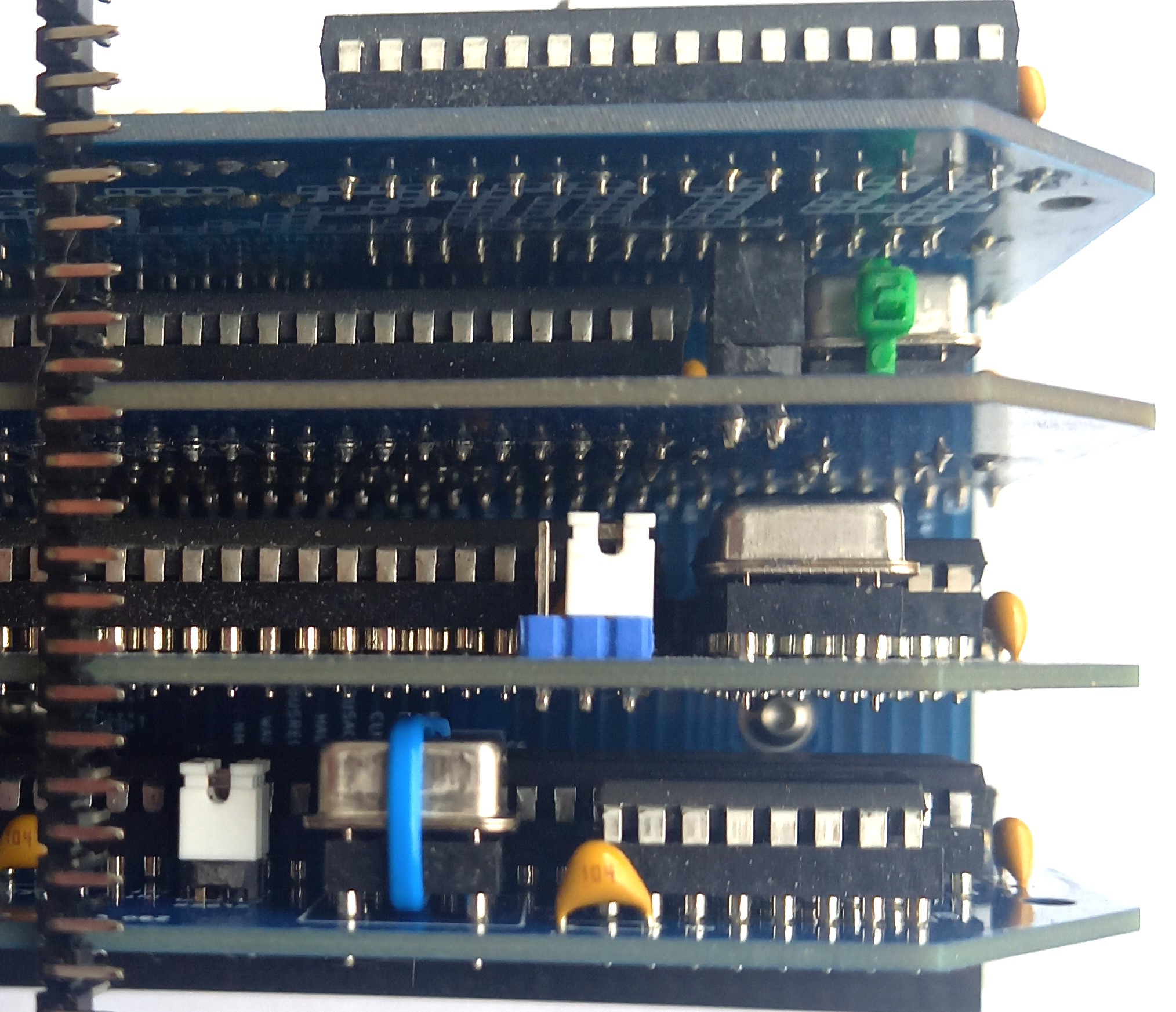
I must admit that I am surprised by the 0.6" spacing problem, I have checked my kits all and have not noticed a problem with the quartz generator in the socket. Yes, PS2, DB9, IDC connectors mounted vertically will cause problems, but the value of the slots is low enough that leaving one is not painful (in the case of DIN41612 it would be a noticeable loss and that is why 0.8" spacing is used there).
Steve Cousins
Mar 4, 2023, 8:39:08 AM3/4/23
to retro-comp
With my Z50Bus kits I supply a spacer to ensure the cards, which are not very stable, to not get too close together and cause shorts with components like oscillators. Given that I don't see 0.6" spacing as a problem.
Steve Cousins
Mar 4, 2023, 8:45:49 AM3/4/23
to retro-comp
Below is a list of the questions, scores, comments and my conclusions.
Question 1: Should we include a module size suggestion of 4"/4000mil/101.6mm long? (that allows space for the full 40/80 pin headers)
The initial specification should not contain recommendations on the size and shape of the modules except the size of the connector. The recommended size and shape can be amended later. As long as the pin layout is specified, the modules will work in compatible backplanes, although they may not fit in certain configurations or builds.
Question 2: Should we include a module size suggestion of 3.9"/3900mil/99mm long? (for those who want consistency with RC2014 39-pin long modules and for a wider choice of low cost PCB manufacturers)
Question 3: Should we include a module size suggestion similiar to the RC2014 Classic 2 low profile modules? (4"/4000mil/101.6mm long by 1"/1000mil/25.4mm high)
yes, X dimension on drawing for 1, with table of recommended X.
Question 4: Should we include a larger module size, perhaps 4"/4000mil/101.6mm square? (particular well suited to prototyping but also allows greater functionality or nicer component spacing and labelling)
Given there is no standard established shape what is wrong with modules may be taller or longer than the suggested profiles but this may cause problems with cases.
Question 5: Should we recommend the PCB extends below the header mounting holes by 0.15"/150mil/3.81mm as proposed by Tadeusz yesterday?
maybe, but no extension past plastic support of dual row header
Question 6: Should we recommend the same size 45 degree bevel and the same curve radius as Spencer's RC2014 modules, or should we recommend different sizes or shapes to differentiate new RCBus modules from RC2014 modules?
Not a fan of the curve and 45 degree bevel at all along with the bullet hole. Hinders part placement. Too much like RC2014. I'm going to come out with a FPGA board it will grow vertically some what.
Question 7: Should we recommend header pins be centred along the length of the board, rather than be offset like Spencer's RC2014 standard size modules?
pin 1 to left edge should match spencers modules, centred on wider module.
Question 8: Anything else we need to decide on this issue?
Question 11: Should the backplane include a dedicated 3V3 pin?
No. Current backplanes are not prepared for this, the number of modules requiring this voltage in complete kits is small, additional voltages should be provided by the module which requires them (an implicit example is RS232 with MAX232 which generates +10V and -10V), the only safe place to provide sufficiently wide tracks is 40-80.
Mark T suggested it would be better to put them near IEI and IEO (pins 38 and 39, previously known as USER 6 and 7). Mark's reasons were to keep the new pins free for other processors and proximity to the back of the PCB is more convenient for link wires etc. As the likely implementation will involve jumpers on the backplane to select daisy chain or direct connections there might be a space issue near IEI and IEO. Also, USER 6 and 7 are more likely to be used by existing designs than the new pins.
Yes. The proposed circuit allows the cascade to be connected using jumpers, no wire connections are needed to implement it.
Question 13: Should we call the fixed function pins "common pins/signals"?
These are the pins that have a single clearly defined function, so mainly the standard RC2014 bus signals.
Other options are "Base pins/signals" or "Fixed function pins/signals" or "Core pins/signals" or "Standard pins/signals" or ???.
I think to discuss signals collectively would be Standard, Enhanced and Extended. With Extended qualified by processor group. Also with Enhanced and Extended not being inclusive of the subset.
Question 14: Should we call the multi-function (ie. processor specific or use case dependent) pins/signals "Extended"?
These are the pins currently named n## and include the RC2014 USER pins. I 've found that they need a simple name when trying to document them.
Other options are "Multi-function" or ???
I think extended is a good term
Question 15: Should the multi-function pins be identified by labels of the form n## (eg. n41)?
If not what should they be labelled?
Maybe the solution would be to call them by the names of the RCZ*80 bus with a # or * sign?
Question 16: Should we have a logo of some sort for RCBus?
The alternative is just to use "RCBus".
yes, with the text as a fallback
Question 17: Should we recommend a minimum spacing between sockets of 0.6"/600mil/15.24mm?
This is the spacing I use for SC112, SC113, SC116 and on my motherboard designs.
The RC2014 backplanes are 0.65"/650mil/16.51mm.
Yes. A minimum spacing of 0.6" is sufficient.
Question 18: Should we suggest a wide spacing of 0.8"/800mil/20.32mm as an alternative?
This give more wiggle room but it is not enough for really large components. The alternative is to simply say there will be odd cases where you need to fit the module in the last slot or have it cover a second (unusable) slot.
No. I think that wide modules can occupy two slots, something like in 19" racks - 2U
Question 19: Should the labels for the bus signals include a symbol/character to indicate active low?
Yes. This is a clear signal indication
Question 20: Is there anything fundamentally wrong with the attached render of a backplane?
Kind of... I'd use top side for the ground fill and the bottom for the signals (or the opposite way)... No real need for that wide traces, especially given that we operate with CMOS logic. At the same time, having a ground plane will reduce EMI
All this discussion makes me think why wouldn't we do ECB instead :) Good quality, although a tad pricey, DIN 41612 connectors. Better pinout than RC2014... And if you fancy not buffering your bus - just don't do that :). Andrew Lynch (N8VEM), one of the people that IMHO restarted the Z80 interest among hobbyists 15 or so years ago, is now working on 100 mm x 100 mm version of ECB. A bit more modular than the original approach. Still buffered bus. Still ECB pinout / DIN 41612 connectors.
==============================================================================
Question 1: Should we include a module size suggestion of 4"/4000mil/101.6mm long? (that allows space for the full 40/80 pin headers)
Voting score: 15
Some of the comments:
Some of the comments:
The initial specification should not contain recommendations on the size and shape of the modules except the size of the connector. The recommended size and shape can be amended later. As long as the pin layout is specified, the modules will work in compatible backplanes, although they may not fit in certain configurations or builds.
Yes but note the RC2014 size and why
Weak yes... I'd rather keep module to 100 mm x 100 mm (or even 100 mm x 80 mm... is anyone still using Eagle?)
Conclusion:
We should include this as a suggestion module length.
==============================================================================
We should include this as a suggestion module length.
==============================================================================
Question 2: Should we include a module size suggestion of 3.9"/3900mil/99mm long? (for those who want consistency with RC2014 39-pin long modules and for a wider choice of low cost PCB manufacturers)
Link to or appendix the RC2014 ones as commonly used profiles.
I mean - for interoperability it doesn't matter if your card is the shape of a dinosaur providing it has the connector and flat in the right place.
I mean - for interoperability it doesn't matter if your card is the shape of a dinosaur providing it has the connector and flat in the right place.
Yes, add a reference to Spencer's specs
Conclusions:
Include link to rc2014.co.uk
==============================================================================
Include link to rc2014.co.uk
==============================================================================
Question 3: Should we include a module size suggestion similiar to the RC2014 Classic 2 low profile modules? (4"/4000mil/101.6mm long by 1"/1000mil/25.4mm high)
Voting score: 12
Some of the comments:
Some of the comments:
yes, X dimension on drawing for 1, with table of recommended X.
No, I never cared for low profile modules... Always looked like a waste of backplane space ;)
Conclusion:
We should suggest Classic 2 profile as one possible size of module.
==============================================================================
We should suggest Classic 2 profile as one possible size of module.
==============================================================================
Question 4: Should we include a larger module size, perhaps 4"/4000mil/101.6mm square? (particular well suited to prototyping but also allows greater functionality or nicer component spacing and labelling)
Voting score: 16
Some of the comments:
Some of the comments:
Given there is no standard established shape what is wrong with modules may be taller or longer than the suggested profiles but this may cause problems with cases.
Yes, although, as specified before, 100 mm x 80 mm or 100 mm x 100 mm would be my preference.
Conclusion:
We should suggest a large module size.
==============================================================================
We should suggest a large module size.
==============================================================================
Question 5: Should we recommend the PCB extends below the header mounting holes by 0.15"/150mil/3.81mm as proposed by Tadeusz yesterday?
Voting score: 10
Some of the comments:
Some of the comments:
maybe, but no extension past plastic support of dual row header
Conclusion:
Yes, we should recommend the PCB extends to the bottom edge of the plastic of the header.
==============================================================================
Yes, we should recommend the PCB extends to the bottom edge of the plastic of the header.
==============================================================================
Question 6: Should we recommend the same size 45 degree bevel and the same curve radius as Spencer's RC2014 modules, or should we recommend different sizes or shapes to differentiate new RCBus modules from RC2014 modules?
Some of the comments:
Slightly different dimensions
Slightly different dimensions
Not a fan of the curve and 45 degree bevel at all along with the bullet hole. Hinders part placement. Too much like RC2014. I'm going to come out with a FPGA board it will grow vertically some what.
Don't care but having something is helpful
Weak no. 45 bevel is cute, but it eats up PCB space, and doesn't add to functionality. If decided on a rectangular shape, perhaps a couple of M3 holes on each one of the corners would be nice (so standoffs can be used to build a more rigid construction, say 5 mm (or 5.08 mm if we want to be imperial system compliant) from the top and left/right edges.
Voting score: -10
Conclusion:
A slightly different module shape should be recommended.
==============================================================================
Conclusion:
A slightly different module shape should be recommended.
==============================================================================
Question 7: Should we recommend header pins be centred along the length of the board, rather than be offset like Spencer's RC2014 standard size modules?
Voting score: 5
Some of the comments:
Some of the comments:
pin 1 to left edge should match spencers modules, centred on wider module.
Don't see that it matters either way
No. Instead, pin 1 center should be placed 1.27 mm (50 mil for fellow US people) to the right from the left edge of the board. In this case, the connector will be "centered" for 101.6 mm / 4 in board.
Conclusion:
The header should be centred for modules that are 4"/101.6mm long.
==============================================================================
The header should be centred for modules that are 4"/101.6mm long.
==============================================================================
Question 8: Anything else we need to decide on this issue?
Voting score: -12
Conclusion:
Looks like we should now be able to pin down the recommendations for module sizes.
==============================================================================
Conclusion:
Looks like we should now be able to pin down the recommendations for module sizes.
==============================================================================
Question 11: Should the backplane include a dedicated 3V3 pin?
The alternative is to generate 3V3 on any module that needs it. Having a pin on the bus for this will not mean the supply is always present, so will that mean a module needing 3V3 will require a suitable power module to be present, or does it mean those modules needing 3V3 will have a regulator on them anyway plus a jumper to determine if its 3V3 supply is connected to the bus?
I've faced the same issue with my designs that have a voltage supervisor. I initially included the supervisor on processor modules but later introduced power supply modules that include a supervisor. So now some combination of boards mean I have two supervisors!
I've faced the same issue with my designs that have a voltage supervisor. I initially included the supervisor on processor modules but later introduced power supply modules that include a supervisor. So now some combination of boards mean I have two supervisors!
I also think 3.3V is nice, but the Paralax Propeller and WiFi modules did just fine without it. The BAI/BAO cascade is also a bit of a leap into the future, especially as we still don't have established request signals to invoke even one rather than several DMA chips. However, if we want to use such a cascade, we need to provide for it on the backplane, otherwise we will have unnecessary wire connections.
Voting score: 2
Some of the comments:
Some of the comments:
No. Current backplanes are not prepared for this, the number of modules requiring this voltage in complete kits is small, additional voltages should be provided by the module which requires them (an implicit example is RS232 with MAX232 which generates +10V and -10V), the only safe place to provide sufficiently wide tracks is 40-80.
Would be nice but where is a good question.
Weak yes, I like the proposal of using pins 40/80 for it
Conclusion:
No clear consensus. Best leave it unspecified for now.
==============================================================================
Question 12: Should BAI and BAO be on pins 42 and 43?
No clear consensus. Best leave it unspecified for now.
==============================================================================
Question 12: Should BAI and BAO be on pins 42 and 43?
Mark T suggested it would be better to put them near IEI and IEO (pins 38 and 39, previously known as USER 6 and 7). Mark's reasons were to keep the new pins free for other processors and proximity to the back of the PCB is more convenient for link wires etc. As the likely implementation will involve jumpers on the backplane to select daisy chain or direct connections there might be a space issue near IEI and IEO. Also, USER 6 and 7 are more likely to be used by existing designs than the new pins.
Voting score: 1
Some of the comments:
Some of the comments:
Yes. The proposed circuit allows the cascade to be connected using jumpers, no wire connections are needed to implement it.
Placing the BAI/BAO cascade on pins 77 and 78 does not seem to be a good idea. If you don't want to use vias, then put the two 2x3 pin headers side by side. Maintaining 0.6" spacing between the slots will be impossible. I consider the return to wiring the module to the backplane to be too much of a step backwards. The drawing also included the 3.3V line - the only sensible place for the backplane.
I think not impossible, just a little bit awkward. Difficult to change links without removing modules. The headers for the links could be put on the bottom side of the backplane but then soldering the backplane connectors and header pins for the links is a little tricky.
I was considering a similar arrangement as links on the middle pair of connectors can allow a daisy chain using any pair of user pins, but doesn’t work with the proposed standard for IEI/IEO on n38 and N39.
I think n40 and n80 as a daisy chain would also work for BAI/BAO. Then only extended width cards could use BAI/BAO, but that doesn’t seem to me to be a disadvantage.
Weak no. Without looking much at the layout, I'd put them near IEI and IEO pins.
Conclusion:
No clear consensus.
We need an answer as the backplane will need a mechanism to support this, or we will be left with flying leads.
A little debate needed I think.
==============================================================================
No clear consensus.
We need an answer as the backplane will need a mechanism to support this, or we will be left with flying leads.
A little debate needed I think.
==============================================================================
Question 13: Should we call the fixed function pins "common pins/signals"?
These are the pins that have a single clearly defined function, so mainly the standard RC2014 bus signals.
Other options are "Base pins/signals" or "Fixed function pins/signals" or "Core pins/signals" or "Standard pins/signals" or ???.
Voting score: 5
Some of the comments:
Some of the comments:
I think to discuss signals collectively would be Standard, Enhanced and Extended. With Extended qualified by processor group. Also with Enhanced and Extended not being inclusive of the subset.
Conclusion:
Not entirely clear.
I think perhaps collective names for these groups should be "Standard" (for RCBus 40-pin) and "Enhanced" (for RCBus 80-pin)
==============================================================================
Not entirely clear.
I think perhaps collective names for these groups should be "Standard" (for RCBus 40-pin) and "Enhanced" (for RCBus 80-pin)
==============================================================================
Question 14: Should we call the multi-function (ie. processor specific or use case dependent) pins/signals "Extended"?
These are the pins currently named n## and include the RC2014 USER pins. I 've found that they need a simple name when trying to document them.
Other options are "Multi-function" or ???
Voting score: 6
Some of the comments:
Some of the comments:
I think extended is a good term
Yes, call them CPU-dependent? Extended can mean many things
Conclusion:
Not entirely clear.
I think perhaps a collective name for this group should be "Extended"
==============================================================================
Not entirely clear.
I think perhaps a collective name for this group should be "Extended"
==============================================================================
Question 15: Should the multi-function pins be identified by labels of the form n## (eg. n41)?
If not what should they be labelled?
Voting score: 5
Some of the comments:
Some of the comments:
Maybe the solution would be to call them by the names of the RCZ*80 bus with a # or * sign?
I think usefull to have a common method of describing the physical connection, not sure about n41 etc as n prefix is common for active low. Is pin41 or p41 not easy to use?
Convention seems to be to give them a base name and where needed refer to them with a / list of their forms - at least that's what half the microcontrollers seem to do.
Weak yes... I don't have a better suggestion
Conclusion:
Not entirely clear.
I think they should be referred to as "pin ##" (where there is room) or "p##" where space is tight.
==============================================================================
Not entirely clear.
I think they should be referred to as "pin ##" (where there is room) or "p##" where space is tight.
==============================================================================
Question 16: Should we have a logo of some sort for RCBus?
The alternative is just to use "RCBus".
Voting score: 6
Some of the comments:
Some of the comments:
yes, with the text as a fallback
I have a dilemma here, there should be a recognisable designation, clearly indicating the supported standard, but there may be people who see this as an attempt to build a new brand. I will certainly leave the 1980s style lettering/logo in my backplane, will I use it in the modules? I do not know.
do you intend to copyright or control how the logo can be used?
Does it matter - if someone makes one then fine if not then fine 8)
Yes. Do we have graphic designers? :)
Conclusion:
Not unanimous but it looks like we want a logo.
I for one have no interest in copyright or control of the logo.
==============================================================================
Not unanimous but it looks like we want a logo.
I for one have no interest in copyright or control of the logo.
==============================================================================
Question 17: Should we recommend a minimum spacing between sockets of 0.6"/600mil/15.24mm?
This is the spacing I use for SC112, SC113, SC116 and on my motherboard designs.
The RC2014 backplanes are 0.65"/650mil/16.51mm.
Voting score: 9
Some of the comments:
Some of the comments:
Yes. A minimum spacing of 0.6" is sufficient.
I prefer 16.51. 15.24 is too tight with socketed can oscillators.
Weak no for 0.6". It seems to tight in some cases - socketed oscillators, vertical connectors, D-sub, Mini-DIN, RJ45 modular connectors
Conclusion:
On balance it looks like 0.6" is favoured.
Perhaps we should just suggest 0.6" and 0.8" are likely to be commonly used spacings.
==============================================================================
On balance it looks like 0.6" is favoured.
Perhaps we should just suggest 0.6" and 0.8" are likely to be commonly used spacings.
==============================================================================
Question 18: Should we suggest a wide spacing of 0.8"/800mil/20.32mm as an alternative?
This give more wiggle room but it is not enough for really large components. The alternative is to simply say there will be odd cases where you need to fit the module in the last slot or have it cover a second (unusable) slot.
Voting score: -1
Some of the comments:
Some of the comments:
No. I think that wide modules can occupy two slots, something like in 19" racks - 2U
no, 17 is just a recommendation
Does it matter. Specify the minimum spacing and "wider spacings may be used and may be more convenient"
Yes for 0.8" alternative... Maybe someone would design a backplane with both 0.6" and 0.8", e.g., 3 slots with 0.6" spacing and two with 0.8" spacing? 0.6" is really narrow for almost any kind of vertical connectors
Conclusion:
No consensus.
See conclusion to question 17.
==============================================================================
No consensus.
See conclusion to question 17.
==============================================================================
Question 19: Should the labels for the bus signals include a symbol/character to indicate active low?
Voting score: 14
Some of the comments:
Some of the comments:
Yes. This is a clear signal indication
yes, pick something that works well on silkscreen, I think lower case n rather than /, with upper case for the rest of the label.
Conclusion:
Polarity should be included in the signal name.
I think the suggestion of lower case n as a prefix for active low signals followed by all upper case signal name, should be suggested as the naming convention.
==============================================================================
Polarity should be included in the signal name.
I think the suggestion of lower case n as a prefix for active low signals followed by all upper case signal name, should be suggested as the naming convention.
==============================================================================
Question 20: Is there anything fundamentally wrong with the attached render of a backplane?
Voting score: -7
Some of the comments:
Some of the comments:
Kind of... I'd use top side for the ground fill and the bottom for the signals (or the opposite way)... No real need for that wide traces, especially given that we operate with CMOS logic. At the same time, having a ground plane will reduce EMI
Conclusion:
Close to unanimous as many gave no opinion. So no major objections to the backplane render.
==============================================================================
Question 21: Anything else we need to decide on this issue?
Voting score: -7
Some of the comments:
Close to unanimous as many gave no opinion. So no major objections to the backplane render.
==============================================================================
Question 21: Anything else we need to decide on this issue?
Voting score: -7
Some of the comments:
All this discussion makes me think why wouldn't we do ECB instead :) Good quality, although a tad pricey, DIN 41612 connectors. Better pinout than RC2014... And if you fancy not buffering your bus - just don't do that :). Andrew Lynch (N8VEM), one of the people that IMHO restarted the Z80 interest among hobbyists 15 or so years ago, is now working on 100 mm x 100 mm version of ECB. A bit more modular than the original approach. Still buffered bus. Still ECB pinout / DIN 41612 connectors.
Conclusion:
No major issues raised.
No major issues raised.
Tadeusz Pycio
Mar 4, 2023, 9:42:32 AM3/4/23
to retro-comp
The discussion about supporting the 3.3V line on the RCBus should go along with the fundamental question of backplane functionality. At present it is quasi-active, sometimes there are voltage regulators, a reset supervisor, often a RESET button. No clearly defined functionality. Adding another voltage will force the addition of a voltage regulator, so the question is - should the backplane be fully passive and the functions of voltage sources and reset circuits be taken over by a special module (similar to SC142) or should this functionality be provided by the backplane?
Tadeusz Pycio
Mar 4, 2023, 10:05:34 AM3/4/23
to retro-comp
I will answer my own question ;-) The backplane should contain voltage regulators, reset supervisor circuits and in dreams a USB connector (USB type B?) along with a serial-usb converter, which would require changing the meaning of pins 75 and 76 (RX2/TX2) to CTS/RST to provide full serial port support. I'll admit to being annoyed by the hanging usb-serial converters along with their tendency to disengage when the cable is moved.
Steve Cousins
Mar 5, 2023, 12:49:00 PM3/5/23
to retro-comp
I've tried to create an RCBus-80 module template with power running below the header, as previously discussed.
I've based it on the dimension drawing Tadeusz provided earlier but I've reduced the 45 degree bevel further, to 0.3", and added tiny curves to the bottom corners (nicer to handle)
Thoughts appreciated.
Steve
Wayne Warthen
Mar 5, 2023, 3:07:52 PM3/5/23
to retro-comp
A thing of beauty. Nice work Steve.
-Wayne
TonyD
Mar 6, 2023, 5:11:36 AM3/6/23
to retro-comp
Hi
Sorry I'm a bit late, my votes on the first set of proposals are:
1. Yes
2. No
3. No
4. Yes
5. Yes
6. No
7. Yes
8. Not at the moment
Tony
Sorry I'm a bit late, my votes on the first set of proposals are:
1. Yes
2. No
3. No
4. Yes
5. Yes
6. No
7. Yes
8. Not at the moment
Tony
Steve Cousins
Mar 7, 2023, 6:35:50 PM3/7/23
to retro-comp
Attached is the latest draft of the RCBus specification. It includes most of the conclusions from the recent questions and answers.
Quite a lot of the text is from Alan - thanks for that.
Some of the terminology doesn't feel right to me yet.
Comments appreciated.
TonyD
Mar 8, 2023, 5:00:10 AM3/8/23
to retro-comp
The RCBus specification is looking really good, thanks to Steve and all for making it happen
I was wondering how the RCBus would handle CPU's with multiplexed Address and Data Lines and a separate Address Latch Enable (ALE) signal, such as the 8032/52.
I'm guessing you would have a latch on CPU PCB and use the latched Address on the bus
Tony
I was wondering how the RCBus would handle CPU's with multiplexed Address and Data Lines and a separate Address Latch Enable (ALE) signal, such as the 8032/52.
I'm guessing you would have a latch on CPU PCB and use the latched Address on the bus
Tony
Steve Cousins
Mar 8, 2023, 5:02:28 AM3/8/23
to retro-comp
Hi Tony,
Yes, that would be consistent with the RCBus philosophy.
Steve
Alan Cox
Mar 8, 2023, 10:03:03 AM3/8/23
to retro-comp
On Wed, 8 Mar 2023, 10:00 'TonyD' via retro-comp, <retro...@googlegroups.com> wrote:
The RCBus specification is looking really good, thanks to Steve and all for making it happen
I was wondering how the RCBus would handle CPU's with multiplexed Address and Data Lines and a separate Address Latch Enable (ALE) signal, such as the 8032/52.
I'm guessing you would have a latch on CPU PCB and use the latched Address on the bus
This is what the existing cards for such processors do. It's usually just a 74HCT573
Alan
Steve Cousins
Mar 9, 2023, 5:39:54 AM3/9/23
to retro-comp
Comments and feedback seem to have run their course so I've tidied up the specification and attached a v1.0 release candidate.
The issues with no clear consensus I have either taken my best guess at the most acceptable solution or left them out of v1.0. So, for example, the BAI/BAO pins have been left at 42/43 where there is room for configuration jumpers.
There are probably lots that could be improved on and quite a few consistency and terminology issues, but I think we need to release a v1.0 asap.
One little thing I've just noticed is Alan's contributions refers to "cards" while my contributions refer to "modules". Which should be use to describe what are "modules" in the RC2014 universe?
Any feedback you have would be appreciated asap so we can move forward quickly.
Steve
dhen...@gmail.com
Mar 9, 2023, 10:10:45 AM3/9/23
to retro-comp
The specification looks good to me. A couple of minor suggestions:
1. The version should actually say '1.0'
2. The spec should include an 'official' URL, where future readers can go to check whether there are updates. Since Steve as done the bulk of the work on this, I think it makes sense for him to host it on his site (assuming he agrees!).
Thanks for all the work!
Denis
On Thursday, 9 March 2023 at 10:39:54 UTC Steve Cousins wrote:

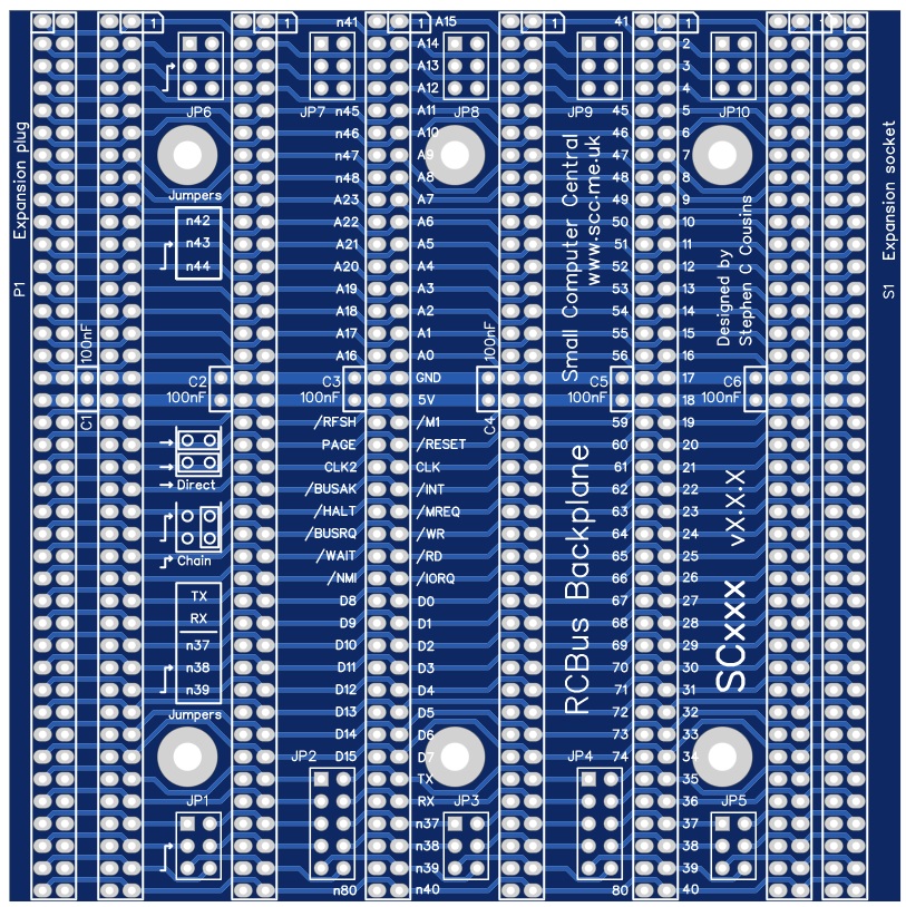
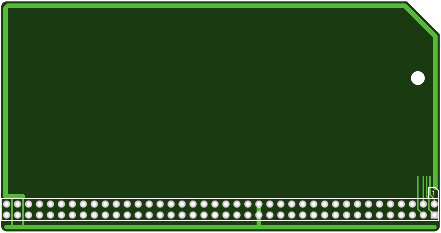
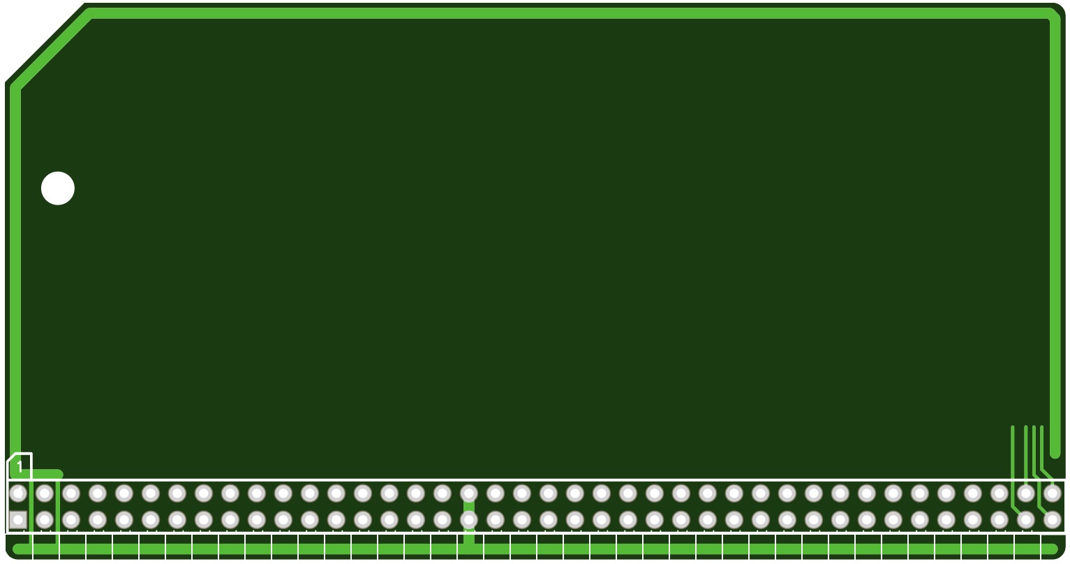
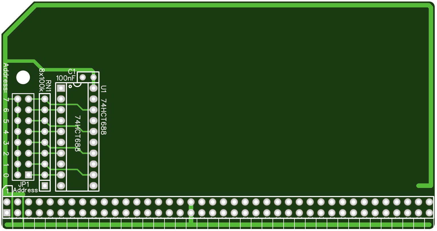
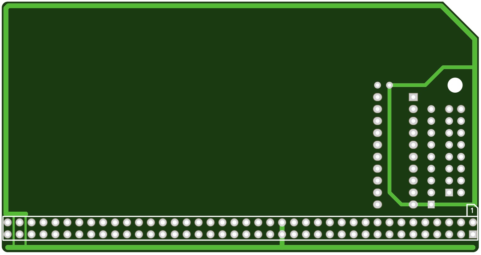
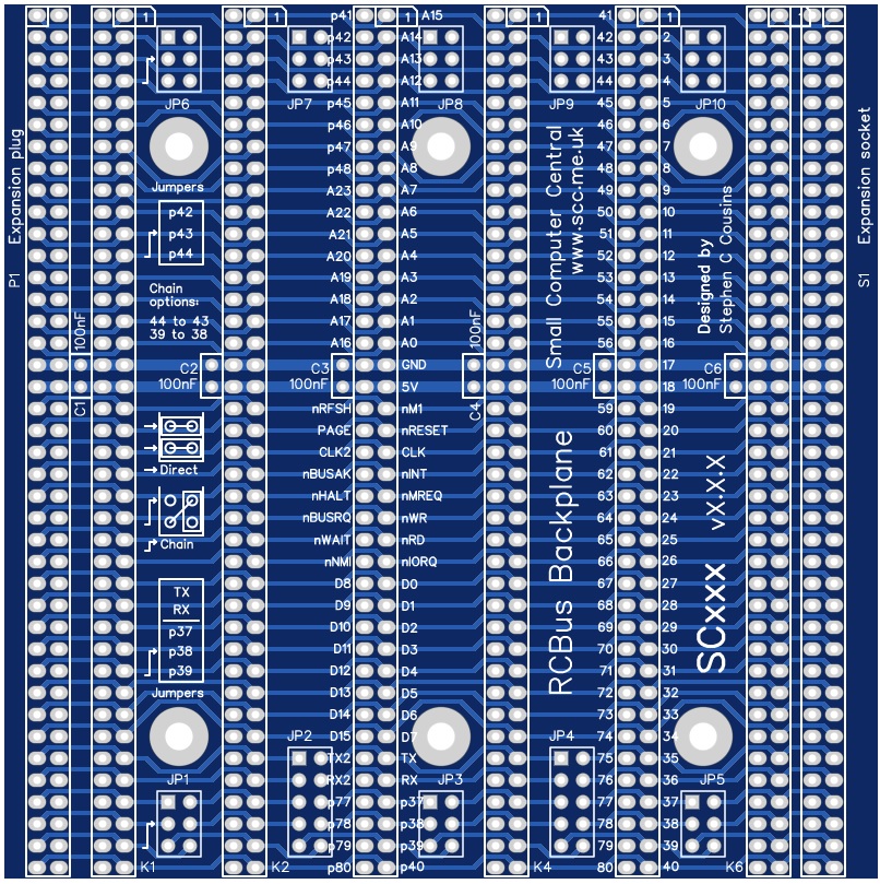
Kurt Pieper
Mar 9, 2023, 11:44:49 AM3/9/23
to retro-comp
Hi Steve,
I like that.
Knowing your good work, I would appreciate it
if a z80/z180 system is offered on the Basic of this bacplane.
I'll be there and keep watching.
greeting
I like that.
Knowing your good work, I would appreciate it
if a z80/z180 system is offered on the Basic of this bacplane.
I'll be there and keep watching.
greeting
Kurt
Tadeusz Pycio
Mar 9, 2023, 12:52:09 PM3/9/23
to retro-comp
1. In the specification, the type of 40-pin angled connector should be changed to asymmetrical if we are to use a lower PCB edge up to 150 mils.
2. We still do not have agreed DMA service request signals (and possibly acknowledgement/termination of service) for the Zx80.
3. The postulated ALE signal (for CPU modules it is unnecessary as latches can be used there) can only be used by a few I/O chips (Z8000 family and 8155, 8256 chips) so I don't know if there is any need to add it.
4. I would suggest increasing the height of the medium PCB to a size of 2200 mils, which will allow the use of the PLCC68 socket and DIP8-20 chips without cramping.
Tadeusz Pycio
Mar 9, 2023, 12:55:32 PM3/9/23
to retro-comp
5. No determination of power distribution source, reset signal (module/backplane)?
Alan Cox
Mar 9, 2023, 7:05:51 PM3/9/23
to Steve Cousins, retro-comp
> One little thing I've just noticed is Alan's contributions refers to "cards" while my contributions refer to "modules". Which should be use to describe what are "modules" in the RC2014 universe?
Modules seems better
.Alan
Alan Cox
Mar 9, 2023, 7:08:46 PM3/9/23
to Tadeusz Pycio, retro-comp
On Thu, 9 Mar 2023 at 17:55, Tadeusz Pycio <ta...@wp.pl> wrote:
>
> 5. No determination of power distribution source, reset signal (module/backplane)?
Current RC allows for these to come from various places. The reset is
>
> 5. No determination of power distribution source, reset signal (module/backplane)?
basically a shared pull down to reset and the power can come from
anywhere providing it comes from one place. Right now that includes
uart modules, backplanes or even power/battery modules.
Reset btw really does need to be that way because many processors have
a bidirectional reset where they will also pull down reset on an
internal reset.
Tadeusz Pycio
Mar 10, 2023, 2:33:52 AM3/10/23
to retro-comp
Hi Alan,
You are right, but such arbitrariness can lead to a situation where there may be several reset circuits in one circuit and none in another. A similar situation occurs with the system clock. The natural place to put the reset and system clock circuits is in the CPU module, although this can be cumbersome with low-profile modules. I believe that the RCBus standard should include a recommendation for the placement of the sources of these signals. The lack of standardisation for the power supply is similarly troublesome.
- System clock: CPU module (recommended) or other module
- Reset circuit: CPU module or backplane (which is to be recommended?).
- Power supply: backplane or power module (which is to be recommended?)
- System clock: CPU module (recommended) or other module
- Reset circuit: CPU module or backplane (which is to be recommended?).
- Power supply: backplane or power module (which is to be recommended?)
Mark T
Mar 10, 2023, 3:51:20 AM3/10/23
to retro-comp
I think it depends on the type of reset circuit used. I like to use the max818 for battery backup to the ram, which then also provides the reset, so it goes wherever the ram goes.
Alan Cox
Mar 10, 2023, 7:02:38 AM3/10/23
to Tadeusz Pycio, retro-comp
Multiple reset sources is normal. Plenty of processors both require an
external reset and provide the reset output for soft resets. For the
clock some processor modules need to provide it because the clock line
in the bus sense is generated from a divider in the processor and is
supposed to be synchronous to the CPU clock.
The clock can come from anywhere. The policy I've been using is
- Anything which has a can oscillator on it has jumpers so that it can either
a) take clock from the bus (no can fitted)
b) provide clock to the card only
c) provide clock to the card and bus
At most it seems you might want to say
"Modules other than dedicated clock modules or CPU modules where the
processor must generate the bus clock should not assume they are
providing the RCbus CLK signal and if capable of providing the RCbus
clock should allow the user to disable that feature./"
Steve Cousins
Mar 10, 2023, 10:48:04 AM3/10/23
to retro-comp
Point 1 noted.
Tadeusz's questions that need answers:
What DMA service request signals do we want in the RCBus-Z80 spec?
Do we want to increase the height on the medium sized module from 2100 to 2200 mils? (that would make them stick up 100 mils above an RC2014 enhanced module)
Brad Hines
Mar 10, 2023, 2:54:27 PM3/10/23
to Steve Cousins, retro-comp
As far as DMA, I am hopeful to see a bus that could support multiprocessing.
It would be a rather long term project for me, but I would find it interesting to work on the hardware and software and arbitration and memory coherency for a system with multiple Z80 or Z180 cards. (Or even a heterogeneous system, am reminded of the Ohio Scientific CIII. It was limited multiprocessing, with the CPUs taking turns, but that kind of thing could be a starting point.)
Admittedly it's a niche. But if that use case can be supported without impacting other use cases, it would be nice.
--
You received this message because you are subscribed to the Google Groups "retro-comp" group.
To unsubscribe from this group and stop receiving emails from it, send an email to retro-comp+...@googlegroups.com.
To view this discussion on the web visit https://groups.google.com/d/msgid/retro-comp/1942c0ee-6a2e-4537-9d36-2109f748ad9en%40googlegroups.com.
Tadeusz Pycio
Mar 10, 2023, 4:25:08 PM3/10/23
to retro-comp
I see there are no suggestions, so I will try to give my own:
pin 45 - DREQ1; DMA chip input signal, requests generated by I/O device (RDY output signal )
pin 46 - DACK1/TEND1; DMA chip output signal, acknowledgements of service request acceptance or transfer termination (depending on the application in question)
pin 47 - DREQ2
pin 48 - DACK2/TEND2
pin 45 - DREQ1; DMA chip input signal, requests generated by I/O device (RDY output signal )
pin 46 - DACK1/TEND1; DMA chip output signal, acknowledgements of service request acceptance or transfer termination (depending on the application in question)
pin 47 - DREQ2
pin 48 - DACK2/TEND2
Alan Cox
Mar 10, 2023, 6:30:12 PM3/10/23
to Steve Cousins, retro-comp
On Fri, 10 Mar 2023 at 15:48, Steve Cousins <steve...@gmail.com> wrote:
>
> Point 1 noted.
>
> Tadeusz's questions that need answers:
>
> What DMA service request signals do we want in the RCBus-Z80 spec?
IMHO put them in a future update of the spec *after* we've got a few
>
> Point 1 noted.
>
> Tadeusz's questions that need answers:
>
> What DMA service request signals do we want in the RCBus-Z80 spec?
cards using and proving the proposal (which seems fine to me on paper)
> Do we want to increase the height on the medium sized module from 2100 to 2200 mils? (that would make them stick up 100 mils above an RC2014 enhanced module)
Alan
Alan Cox
Mar 10, 2023, 6:39:59 PM3/10/23
to Brad Hines, Steve Cousins, retro-comp
> It would be a rather long term project for me, but I would find it interesting to work on the hardware and software and arbitration and memory coherency for a system with multiple Z80 or Z180 cards. (Or even a heterogeneous system, am reminded of the Ohio Scientific CIII. It was limited multiprocessing, with the CPUs taking turns, but that kind of thing could be a starting point.)
Stalling processors using the DMA signals can be done (with some CMOS
processors but tricky with NMOS). It's one thing I also want to try
with something akin to the Apple Z80 card design. For some processors
it is hairy as you can't hold them off the bus long or their brains
fall out due to their internal use of dram cells.
MP is tricky in part because of the main CPU choice but also because
most RCbus cards attach the MMU to the memory not to the processor.
> Admittedly it's a niche. But if that use case can be supported without impacting other use cases, it would be nice.
6809E/6309E probably but the clock signal plumbing is hairy. Both of
them allow you to run different things on the other half of the bus -
and that was routinely done with the video on the other half. However
I think you owuld need a combo CPU and MMU card for most uses.
The Z80 style processors don't really bus share. The old "multi"
anything Z80 systems had their own memory and a communication area via
I/O or fancy dual port memory. Z280 sort of can and has on chip MMU
and a minimal cache.
Tadeusz Pycio
Mar 10, 2023, 6:54:59 PM3/10/23
to retro-comp
MP is tricky in part because of the main CPU choice but also because
most RCbus cards attach the MMU to the memory not to the processor.
Great idea, I need to add a bus release mechanism to my module.
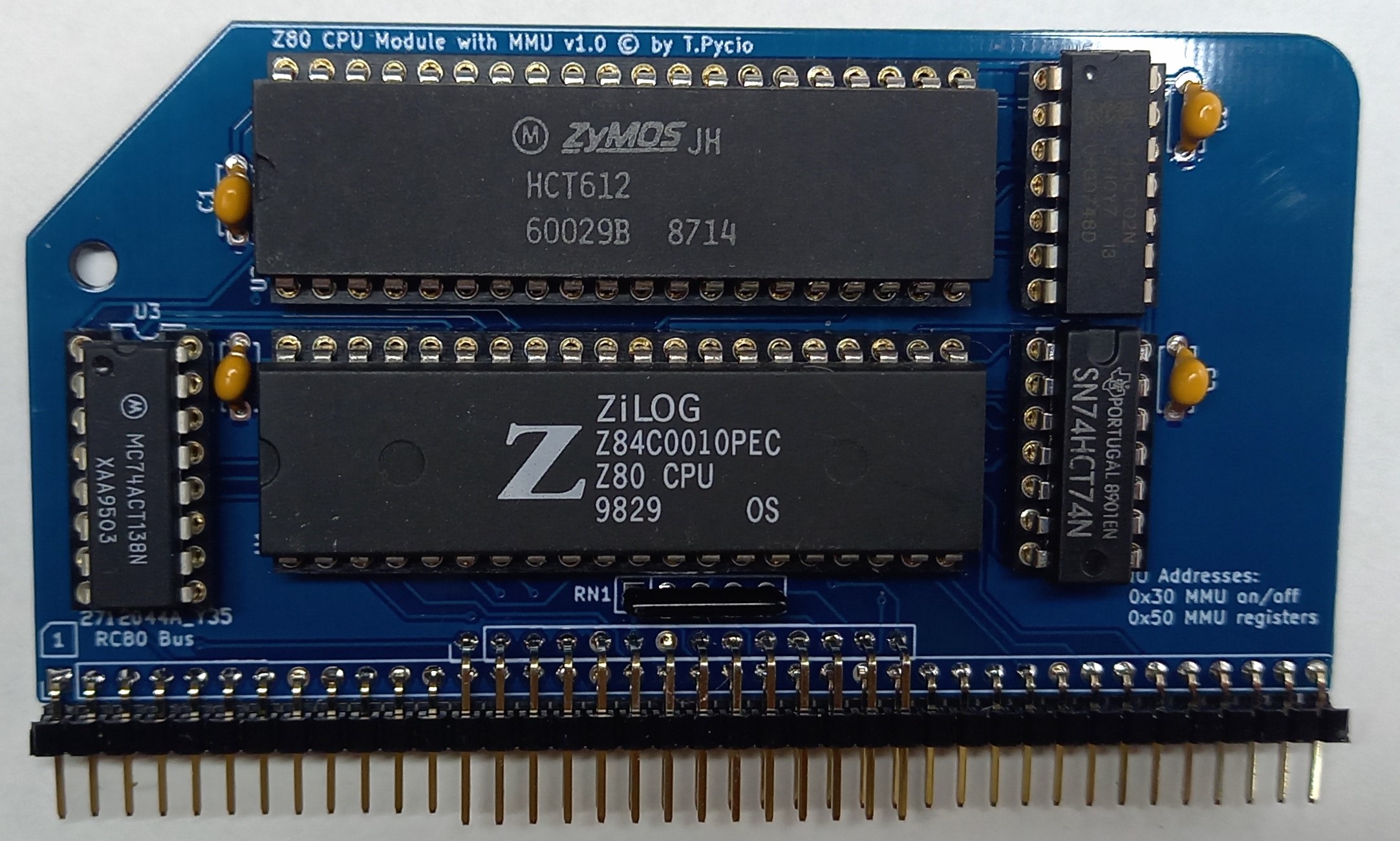
Bill Shen
Mar 10, 2023, 9:01:59 PM3/10/23
to retro-comp
The standard RC2014 bus already can accommodate 64K I/O space, so a painless way of doing multiprocessing is assigned a portion of the I/O space, say 4K, to one port of a 4K dual port RAM and slave processor on the other port of the dual port RAM. Data and program are passing to/from main Z80 processor to the slave processor through the dual port RAM. Assuming 4K I/O space, up to 16 slaves can be accommodated without modifying the RC2014 bus. In fact there is a topic here about multiprocessor Zx80 on RC2014.
Bill
Bill
Steve Cousins
Mar 13, 2023, 7:13:15 AM3/13/23
to retro-comp
Hi All,
I would like to release v1.0 of the RCBus specification but I feel there are still some outstanding issues.
1/ Tadeusz wrote: "I would suggest increasing the height of the medium PCB to a size of 2200 mils, which will allow the use of the PLCC68 socket and DIP8-20 chips without cramping." No one has said yes or no to this idea, only one "don't care". This height would mean the module stands 100 mils above a standard RC2014 module.
2/ If we increase the recommended height of the medium sized module, should we do the same for the small module?
3/ Should we add a website(s) and/or forum URL to support the RCBus. If so, should the forum be this group and what website(s) should we include?
4/ I still think the terminology needs work but that will become clearer as we try to describe products and communicate ideas, so I'm not suggesting any changes at the moment.
Things to do before release 1.0:
1/ Change references to "cards" to "modules".
2/ Add details of single row header pins which have the same profile as the double row header pins. Retain the note that currently the most commonly used profile differs from the double row headers, but add that we recommend the matching profile should be used, especially if the PCB extends below the header pins,
I think a companion document should include details of ideas being considered for the next release of the specification, such as:
RCBus-Z80, DMA signals:
pin 45 - DREQ1; DMA chip input signal, requests generated by I/O device (RDY output signal )
pin 46 - DACK1/TEND1; DMA chip output signal, acknowledgements of service request acceptance or transfer termination (depending on the application in question)
pin 47 - DREQ2
pin 48 - DACK2/TEND2
pin 46 - DACK1/TEND1; DMA chip output signal, acknowledgements of service request acceptance or transfer termination (depending on the application in question)
pin 47 - DREQ2
pin 48 - DACK2/TEND2
If there is anything else that needs to be changed or added to the specification, now would be the time to raise it.
Steve
It is loading more messages.
0 new messages