Minimum heat-sinking requirements? (completely outside of the metal case)

Ronald Nicholson

Steve Haynal

Jayson Bucknell
Steve Haynal

Chris Gerber
--
You received this message because you are subscribed to the Google Groups "Hermes-Lite" group.
To unsubscribe from this group and stop receiving emails from it, send an email to hermes-lite...@googlegroups.com.
To view this discussion on the web visit https://groups.google.com/d/msgid/hermes-lite/756a66b2-348c-4125-8cff-1f2f539eec81o%40googlegroups.com.
Steve Haynal

samuel kallmeyer
To view this discussion on the web visit https://groups.google.com/d/msgid/hermes-lite/8bfb449e-adc5-49c8-8f60-b2360d6739ban%40googlegroups.com.
Steve Haynal
Chris Gerber

k7ul....@gmail.com
Steve Haynal

Doug Schultz
Jayson Bucknell
I've had enough little LDMOS die from thermal runaway to be paranoid. Even if the finals can handle it with the thermal protection the longer term rapid flexing of the circuits doesn't sound good.
If there's a design worked out I'd recommend it as part of the standard kit. I'm not going to try much in the way of WSPR of SSTV until then. It's been a great radio otherwise.
AA7NM

dick_...@hotmail.com
Chris Gerber
--
You received this message because you are subscribed to the Google Groups "Hermes-Lite" group.
To unsubscribe from this group and stop receiving emails from it, send an email to hermes-lite...@googlegroups.com.
To view this discussion on the web visit https://groups.google.com/d/msgid/hermes-lite/4415cbf3-e522-42c5-9d79-1d08b13b850dn%40googlegroups.com.
dick_...@hotmail.com
samuel kallmeyer
To view this discussion on the web visit https://groups.google.com/d/msgid/hermes-lite/4793edac-2111-43b4-965f-410b64894747n%40googlegroups.com.

DL1YCF
per second, but also comes down nearly as quick upon RX.
I certainly would not do JT65 with 5 Watts. However, this was a hot day and the case
temp. was between 25 and 30 degrees Centigrade.
> You received this message because you are subscribed to the Google Groups "Hermes-Lite" group.
> To unsubscribe from this group and stop receiving emails from it, send an email to hermes-lite...@googlegroups.com.

Paul Keller
73's de Paul HB9AXA
PS. It is not nessesary to dremel out the part of the side wall of the case as described in earlier documents. Just sand the bottom in order to make good contact.
Chris Gerber
To view this discussion on the web visit https://groups.google.com/d/msgid/hermes-lite/CAFRyv0KUuz3g-h%3DrN-HT2ZbYOrJvdR9V61wafuUD9t1bNO7%3DcA%40mail.gmail.com.
Steve Haynal
Jayson Bucknell
My love affair has hit a snag. Unless it's something really botched in software I'm afraid I'm going to have to enquire about warranty or repair options. So warned.
dick_...@hotmail.com

Alan Hopper
Jayson Bucknell

Reid Campbell
Are you sure you haven't uploaded one of the Rx only variants which has 10 receivers but TX function removed?
Cheers
Reid
Gi8TME/Mi0BOT
--
You received this message because you are subscribed to the Google Groups "Hermes-Lite" group.
To unsubscribe from this group and stop receiving emails from it, send an email to hermes-lite...@googlegroups.com.
To view this discussion on the web visit https://groups.google.com/d/msgid/hermes-lite/5cce787a-bbe9-4401-ba96-959b21b46e69o%40googlegroups.com.
Alan Hopper
To unsubscribe from this group and stop receiving emails from it, send an email to herme...@googlegroups.com.
Jayson Bucknell
Alan Hopper
Chris Gerber
--
You received this message because you are subscribed to the Google Groups "Hermes-Lite" group.
To unsubscribe from this group and stop receiving emails from it, send an email to hermes-lite...@googlegroups.com.
To view this discussion on the web visit https://groups.google.com/d/msgid/hermes-lite/aac409cb-d053-40f7-ae98-07dd46dab288o%40googlegroups.com.
Chris Gerber
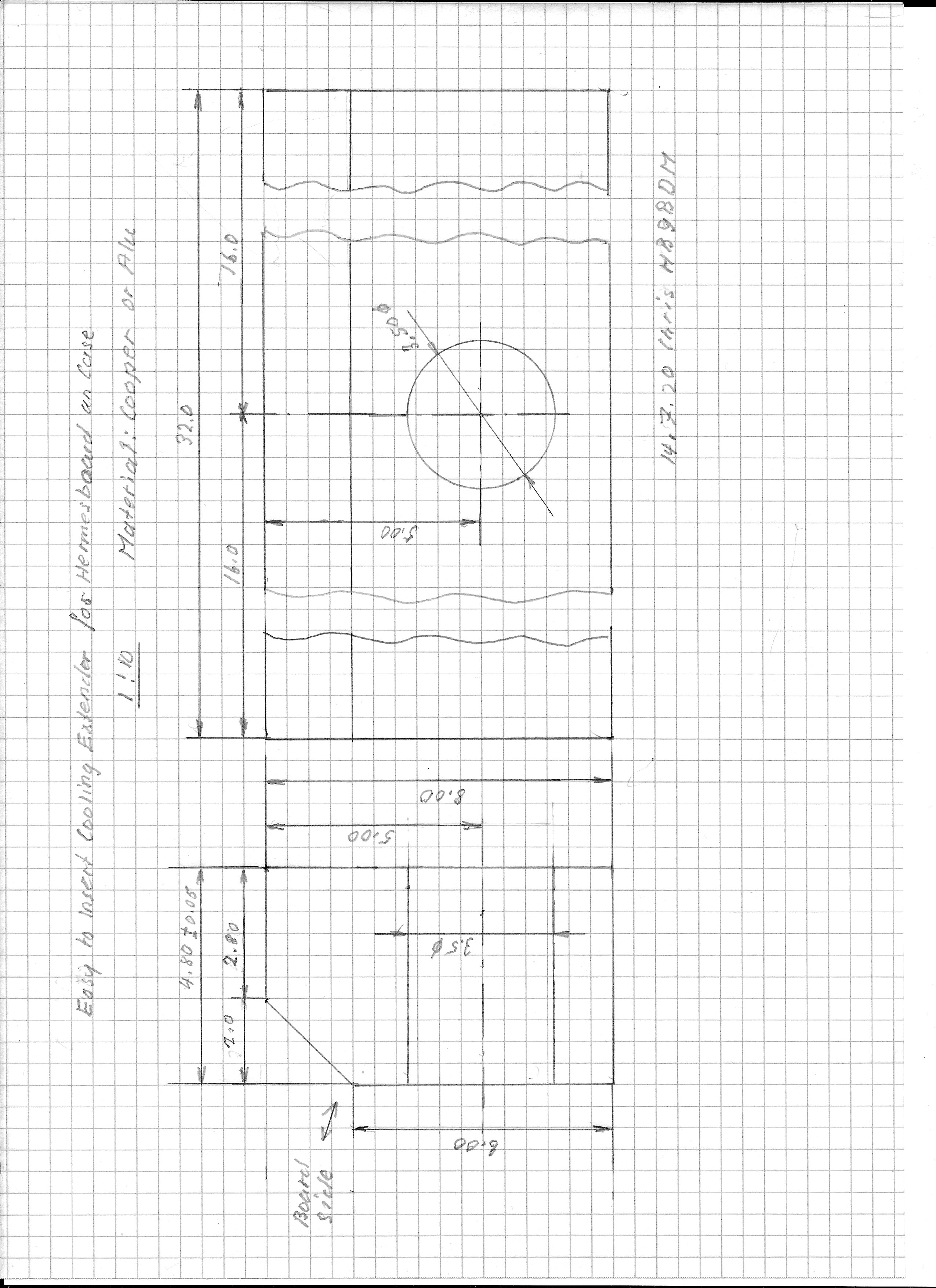
Hermes Lite 2 Heath Dissipation
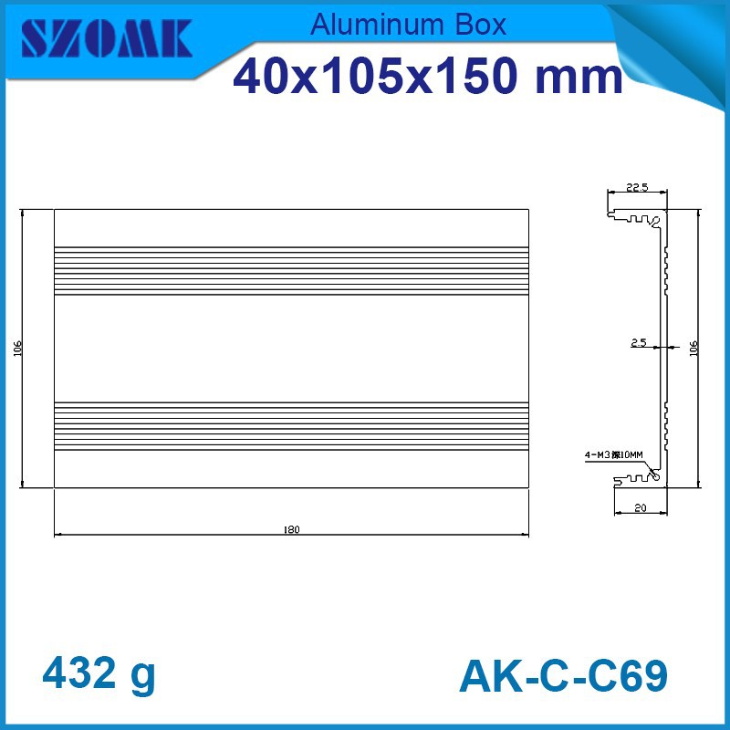
HL2 unit with case of 40mm from Makerfabs and 5mm gap spacing
Put together as described by the developers.
Grinded off the ripen part on the case
Made the following Output Power test and measurements:
Test setup: PSU 13.80V
Current Meter
SWR Power Meter: Daiwa DP-830
50 Ohm 200 W Dummy load
Measurement monitored with PowerSDR 3.5.0 Beta 5
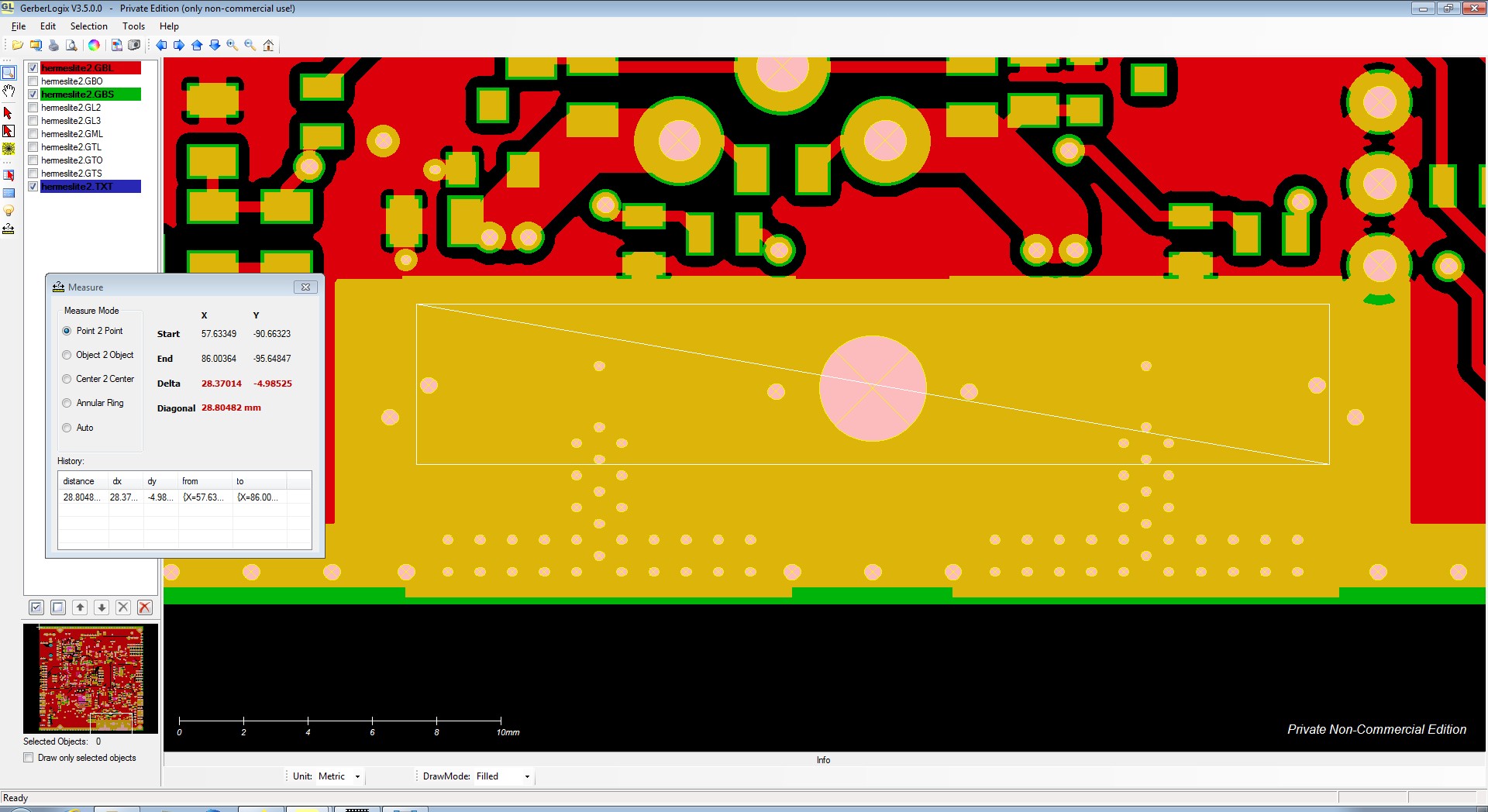
Measured Thermal Contact Surface between Board and Ripen. 35mm by 2mm (Best case)
35mm by 1mm (Worst case, if the board is not shifted to the side)
That is in my aspect a far to small surface to bring away the heath created with 5-6W
Expecting an efficiency of 35 to 50% in AB Mode with the mounted Final MosFets, this then would be in the order of around 6 – 9W. Quit a bit as I have seen on my few mcHF units I have built here.
Total Input on my Test was 13.6v and 1.47A resulting around 20W of course some power is taken of by the board etc.
Again my test shown a time of 8 min to reach 50c Temperature
Added my self developed Cooler Extender I could easy reach 25 min under the same test conditions as above described. That is a excellent range for all Modes used.
I think testing in Mode WSPR is ok, but why not using RTTY. I have seen in my long past ham life to many Radio’s produced, claiming a high output power rate and then in small letter asking not to go above 35% when on RTTY. This was very common and still is.
There is nothing said against this fabulous design and make, but it is always a way to make it good or better, that especially when no redesign is in valve.
I am very please with my HL2, also with my small changes made.
Regards Chris HB9BDM
--
You received this message because you are subscribed to the Google Groups "Hermes-Lite" group.
To unsubscribe from this group and stop receiving emails from it, send an email to hermes-lite...@googlegroups.com.
To view this discussion on the web visit https://groups.google.com/d/msgid/hermes-lite/aac409cb-d053-40f7-ae98-07dd46dab288o%40googlegroups.com.
You received this message because you are subscribed to the Google Groups "Hermes-Lite" group.
To unsubscribe from this group and stop receiving emails from it, send an email to hermes-lite...@googlegroups.com.
Doug Schultz
Jayson Bucknell
Jayson Bucknell
Jayson Bucknell
Steve Haynal
Steve Haynal
Jayson Bucknell
I'm definitely interesting in debugging but it if goes too deep I'll likely have to send it to you.
One thing I would like to check is is there output possible from RF1 or can one otherwise bypass the power amplifier? I'm not sure how to switch it.
73
Jayson
AA7NM
Alan Hopper
Jayson Bucknell
Jayson Bucknell
Alan Hopper
Jayson Bucknell
Steve Haynal
Jayson Bucknell
Steve Haynal
On Saturday, August 15, 2020 at 1:25:02 AM UTC-7, samuel kallmeyer wrote:
In case the corrected design from Chris would fit, I updated the files accordingly.Find them attached.Samuel, f8acb
Ronald Nicholson
samuel kallmeyer
--
You received this message because you are subscribed to the Google Groups "Hermes-Lite" group.
To unsubscribe from this group and stop receiving emails from it, send an email to hermes-lite...@googlegroups.com.
To view this discussion on the web visit https://groups.google.com/d/msgid/hermes-lite/f1f840a8-c080-4bec-96ec-4547df00aef8o%40googlegroups.com.

jpwa...@gmail.com

Jim Ancona
--
You received this message because you are subscribed to the Google Groups "Hermes-Lite" group.
To unsubscribe from this group and stop receiving emails from it, send an email to hermes-lite...@googlegroups.com.
To view this discussion on the web visit https://groups.google.com/d/msgid/hermes-lite/110e6a90-f742-4d78-b7ff-51c67946de5dn%40googlegroups.com.

Lou Scalpati
To view this discussion on the web visit https://groups.google.com/d/msgid/hermes-lite/CAKYY9AK4s5Xs_9ejK42w3NNSJ_cz7mY_-_h7sXyJDQjfY_%3Djrg%40mail.gmail.com.
Steve Haynal
To unsubscribe from this group and stop receiving emails from it, send an email to hermes-lite+unsubscribe@googlegroups.com.
Steve Haynal
There appears to be just under 10 interested, all in the US. I may then check on ordering just 10 units as a trial and ship only to a handful of people in the US.
To unsubscribe from this group and stop receiving emails from it, send an email to hermes-lite+unsubscribe@googlegroups.com.
To view this discussion on the web visit https://groups.google.com/d/msgid/hermes-lite/110e6a90-f742-4d78-b7ff-51c67946de5dn%40googlegroups.com.
--
You received this message because you are subscribed to the Google Groups "Hermes-Lite" group.
To unsubscribe from this group and stop receiving emails from it, send an email to hermes-lite+unsubscribe@googlegroups.com.

Josh Logan

To unsubscribe from this group and stop receiving emails from it, send an email to hermes-lite...@googlegroups.com.
To view this discussion on the web visit https://groups.google.com/d/msgid/hermes-lite/110e6a90-f742-4d78-b7ff-51c67946de5dn%40googlegroups.com.
--
You received this message because you are subscribed to the Google Groups "Hermes-Lite" group.
To unsubscribe from this group and stop receiving emails from it, send an email to hermes-lite...@googlegroups.com.
To view this discussion on the web visit https://groups.google.com/d/msgid/hermes-lite/CAKYY9AK4s5Xs_9ejK42w3NNSJ_cz7mY_-_h7sXyJDQjfY_%3Djrg%40mail.gmail.com.
--
You received this message because you are subscribed to the Google Groups "Hermes-Lite" group.
To unsubscribe from this group and stop receiving emails from it, send an email to hermes-lite...@googlegroups.com.
To view this discussion on the web visit https://groups.google.com/d/msgid/hermes-lite/5b3cfb66-7529-42ed-9fbe-a860fcdffb94o%40googlegroups.com.

vk4...@gmail.com

alexande...@gmail.com
To unsubscribe from this group and stop receiving emails from it, send an email to hermes-lite...@googlegroups.com.
To view this discussion on the web visit https://groups.google.com/d/msgid/hermes-lite/110e6a90-f742-4d78-b7ff-51c67946de5dn%40googlegroups.com.
--
You received this message because you are subscribed to the Google Groups "Hermes-Lite" group.
To unsubscribe from this group and stop receiving emails from it, send an email to hermes-lite...@googlegroups.com.
Chris Gerber
To unsubscribe from this group and stop receiving emails from it, send an email to hermes-lite...@googlegroups.com.
To view this discussion on the web visit https://groups.google.com/d/msgid/hermes-lite/71795937-12a0-4f9a-a903-35c3b324ec77o%40googlegroups.com.
Ronald Nicholson
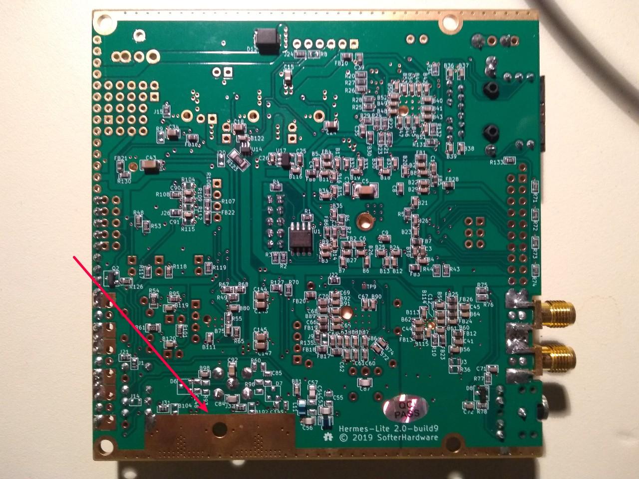
Hi Ron and Group,Some people do heat sink the HL2 in other ways. There is a large exposed area on the bottom of the PCB seen in the picture below. The game is to pipe heat from that area off of the HL2. The HL2 does have temperature monitoring which will disable TX if the temperature is >55C, so you should be safe with experimenting. I like to see the HL2 at below 45C on most days, and below 50C on the hottest days.I would like to see a small aluminum rectangle manufactured that is about the width and length of the exposed area in the picture below, with hole for the screw, and thickness that matches the distance between the bottom of PCB and enclosure surface when the HL2 is mounted in the recommended enclosure. Such a heat shim could be used in the standard enclosure to provide better thermal transfer, or for those who want to use other finned heat sinks as it would provide a spacer so that the bottom of the HL2 PCB is not shorted by the heat sink. Makerfabs does do custom CNC work, and I have HL2 credit with Makerfabs. If someone is willing to draw up such a heat shim in one of the formats accepted by Makerfabs, I can have a bunch made. A free shim goes to the person who draws it up properly.73,Stevekf7o
On Sunday, August 9, 2020 at 11:49:41 AM UTC-7, Ronald Nicholson wrote:If one were to operate a HL2 at 5W outside of the recommended 40mm or 55mm cases (for display purposes, scope probing both sides of the PCB, or ultra-lite SOTA/portable ops), what might be the recommended heat sinking?Has anyone though about or tried a plastic or plexiglass enclosure? (with some sort of heat sink).Thanks,Ronn6ywu

Steve Haynal
To unsubscribe from this group and stop receiving emails from it, send an email to hermes-lite+unsubscribe@googlegroups.com.
To view this discussion on the web visit https://groups.google.com/d/msgid/hermes-lite/110e6a90-f742-4d78-b7ff-51c67946de5dn%40googlegroups.com.
--
You received this message because you are subscribed to the Google Groups "Hermes-Lite" group.
To unsubscribe from this group and stop receiving emails from it, send an email to hermes-lite+unsubscribe@googlegroups.com.
To view this discussion on the web visit https://groups.google.com/d/msgid/hermes-lite/CAKYY9AK4s5Xs_9ejK42w3NNSJ_cz7mY_-_h7sXyJDQjfY_%3Djrg%40mail.gmail.com.
--
You received this message because you are subscribed to the Google Groups "Hermes-Lite" group.
To unsubscribe from this group and stop receiving emails from it, send an email to hermes-lite+unsubscribe@googlegroups.com.
Lou Scalpati
To unsubscribe from this group and stop receiving emails from it, send an email to hermes-lite...@googlegroups.com.
To view this discussion on the web visit https://groups.google.com/d/msgid/hermes-lite/110e6a90-f742-4d78-b7ff-51c67946de5dn%40googlegroups.com.
--
You received this message because you are subscribed to the Google Groups "Hermes-Lite" group.
To unsubscribe from this group and stop receiving emails from it, send an email to hermes-lite...@googlegroups.com.
To view this discussion on the web visit https://groups.google.com/d/msgid/hermes-lite/CAKYY9AK4s5Xs_9ejK42w3NNSJ_cz7mY_-_h7sXyJDQjfY_%3Djrg%40mail.gmail.com.
--
You received this message because you are subscribed to the Google Groups "Hermes-Lite" group.
To unsubscribe from this group and stop receiving emails from it, send an email to hermes-lite...@googlegroups.com.
To view this discussion on the web visit https://groups.google.com/d/msgid/hermes-lite/5b3cfb66-7529-42ed-9fbe-a860fcdffb94o%40googlegroups.com.
--
You received this message because you are subscribed to the Google Groups "Hermes-Lite" group.
To unsubscribe from this group and stop receiving emails from it, send an email to hermes-lite...@googlegroups.com.
To view this discussion on the web visit https://groups.google.com/d/msgid/hermes-lite/d58c3b0d-8fae-4b3a-aa8e-bd2dec779617o%40googlegroups.com.
Jim Ancona
To view this discussion on the web visit https://groups.google.com/d/msgid/hermes-lite/CADON%3D-5fDDSyBRf53%3DfWHkEOcnso%3D07vP7sdqrO-8Siw7_gBgA%40mail.gmail.com.
dick_...@hotmail.com

Winston

Mark Wild

Sid Boyce
I use thick copper plate and on my original HL2, 2 layers of thin copper
plate that bears down on the LDMOS devices and bolted to the side of the
case.
This arrangement was the original recommended by Steve and I installed
on all 3 of my HL2's.
73 ... Sid.
On 26/08/2020 17:40, Ronald Nicholson wrote:
> In addition to heat sinking the bottom of the PCB, does anyone know if
> there is some sort of non-electrically-conductive but thermally
> conductive material can be pressed directly on top of the LDMOS
>
>
>
> Â
> On Sunday, August 9, 2020 at 11:49:41 AM UTC-7, Ronald Nicholson
> wrote:
>
> If one were to operate a HL2 at 5W outside of the recommended
> 40mm or 55mm cases (for display purposes, scope probing both
> sides of the PCB, or ultra-lite SOTA/portable ops), what might
> Has anyone though about or tried a plastic or plexiglass
> enclosure? (with some sort of heat sink).
>
> Thanks,
>
> Ron
> n6ywu
>
> You received this message because you are subscribed to the Google
> Groups "Hermes-Lite" group.
> To unsubscribe from this group and stop receiving emails from it, send
> an email to hermes-lite...@googlegroups.com
> <https://groups.google.com/d/msgid/hermes-lite/784c0421-8b53-43f9-b95b-16ee79e729dbo%40googlegroups.com?utm_medium=email&utm_source=footer>.
--
Sid Boyce ... Hamradio License G3VBV, Licensed Private Pilot
Emeritus IBM/Amdahl Mainframes and Sun/Fujitsu Servers Tech Support
Senior Staff Specialist, Cricket Coach
Microsoft Windows Free Zone - Linux used for all Computing Tasks
Steve Haynal

Jaroslav Škarvada
if you by chance prototype the 55 mm version in the future (with
Makerfab), I will be interested
73! Jaroslav, OK2JRQ
Steve Haynal napsal(a):
>
> Unfortunately the 55mm case clearance is different than the 40mm case.
> There was some discussion about this earlier in this thread. This file
> is only supposed to work with the 40mm case. It would be nice to have
> .stl or .step files for both cases.
>
> 73,
>
> Steve
> kf7o
>
>
>
> On Tuesday, August 25, 2020 at 10:27:43 PM UTC-7, Josh Logan wrote:
>
>
> I did 3D print one from the .stl file. It's too tall to fit under
> the PCB in the 55mm case. If anyones wants me to pull dimensions
> let me know.
>
> 73, KD7HGL
> Josh
>
>
>
>
> <mailto:hermes-lite...@googlegroups.com>.
> https://groups.google.com/d/msgid/hermes-lite/110e6a90-f742-4d78-b7ff-51c67946de5dn%40googlegroups.com
> --
> You received this message because you are subscribed to
> the Google Groups "Hermes-Lite" group.
> To unsubscribe from this group and stop receiving emails
> from it, send an email to
> <mailto:hermes-lite...@googlegroups.com>.
> <https://groups.google.com/d/msgid/hermes-lite/CAKYY9AK4s5Xs_9ejK42w3NNSJ_cz7mY_-_h7sXyJDQjfY_%3Djrg%40mail.gmail.com?utm_medium=email&utm_source=footer>.
> --
> You received this message because you are subscribed to the
> Google Groups "Hermes-Lite" group.
> To unsubscribe from this group and stop receiving emails from
> <mailto:hermes-lite...@googlegroups.com>.
> <https://groups.google.com/d/msgid/hermes-lite/5b3cfb66-7529-42ed-9fbe-a860fcdffb94o%40googlegroups.com?utm_medium=email&utm_source=footer>.
> --
> You received this message because you are subscribed to the Google
> Groups "Hermes-Lite" group.
> To unsubscribe from this group and stop receiving emails from it, send
> <mailto:hermes-lite...@googlegroups.com>.
> <https://groups.google.com/d/msgid/hermes-lite/d58c3b0d-8fae-4b3a-aa8e-bd2dec779617o%40googlegroups.com?utm_medium=email&utm_source=footer>.
Steve Haynal

Samir, OD5SK
Steve Haynal
Samir, OD5SK

Cesc Gudayol
ron.ni...@gmail.com
I ran a small experiment to see how well heat transfer from the Hermes Lite 2 PCB to the side of the 40mm case was helping lower the working temperature.
First I used the HL2 for receive-only for 4 minutes: temp = 30.5 C = 87.0 F
Then I transmitted a wspr signal at 30 dBm (1 Watt).
Initial temperature rise after 2 minutes was: temp = 37.6 C = 99.7 F
After 10 minutes: temp = 42.1 C = 107.7 F
After 1 hour: temp = 47.1 C = 116.8 F
Then I immediately placed one of those small battery-operated personal fans about 4 cm away from the right side of the exterior of the 40mm case, and set the fan on "low" (while still continuously transmitting 20M wspr at 30dBm).
After 2 minutes: temp = 40.1 C = 104.2 F
After 10 minutes: temp = 34.2 C = 93.6 F
That's a 13 C temperature drop from peak, just by adding a bit of airflow around the case exterior. So the thermal conduction from the PCB slot to the case exterior seems to be significant. I wonder if just bolting a large (passive noiseless) external heat sink to the right side of the HL2 case would significantly increase thermal dissipation.
73,Hi Ron and Group,Some people do heat sink the HL2 in other ways. There is a large exposed area on the bottom of the PCB seen in the picture below. The game is to pipe heat from that area off of the HL2. The HL2 does have temperature monitoring which will disable TX if the temperature is >55C, so you should be safe with experimenting. I like to see the HL2 at below 45C on most days, and below 50C on the hottest days.I would like to see a small aluminum rectangle manufactured that is about the width and length of the exposed area in the picture below, with hole for the screw, and thickness that matches the distance between the bottom of PCB and enclosure surface when the HL2 is mounted in the recommended enclosure. Such a heat shim could be used in the standard enclosure to provide better thermal transfer, or for those who want to use other finned heat sinks as it would provide a spacer so that the bottom of the HL2 PCB is not shorted by the heat sink. Makerfabs does do custom CNC work, and I have HL2 credit with Makerfabs. If someone is willing to draw up such a heat shim in one of the formats accepted by Makerfabs, I can have a bunch made. A free shim goes to the person who draws it up properly.
73,Stevekf7o
On Sunday, August 9, 2020 at 11:49:41 AM UTC-7, Ronald Nicholson wrote:
If one were to operate a HL2 at 5W outside of the recommended 40mm or 55mm cases (for display purposes, scope probing both sides of the PCB, or ultra-lite SOTA/portable ops), what might be the recommended heat sinking?
Steve Haynal
Steve Haynal
Steve Haynal
ron.ni...@gmail.com
Winston
Chris Gerber
--
You received this message because you are subscribed to the Google Groups "Hermes-Lite" group.
To unsubscribe from this group and stop receiving emails from it, send an email to hermes-lite...@googlegroups.com.
To view this discussion on the web visit https://groups.google.com/d/msgid/hermes-lite/00414ee9-c68f-484d-9955-4e83bfbf31cco%40googlegroups.com.
Samir, OD5SK
keyboa...@gmail.com
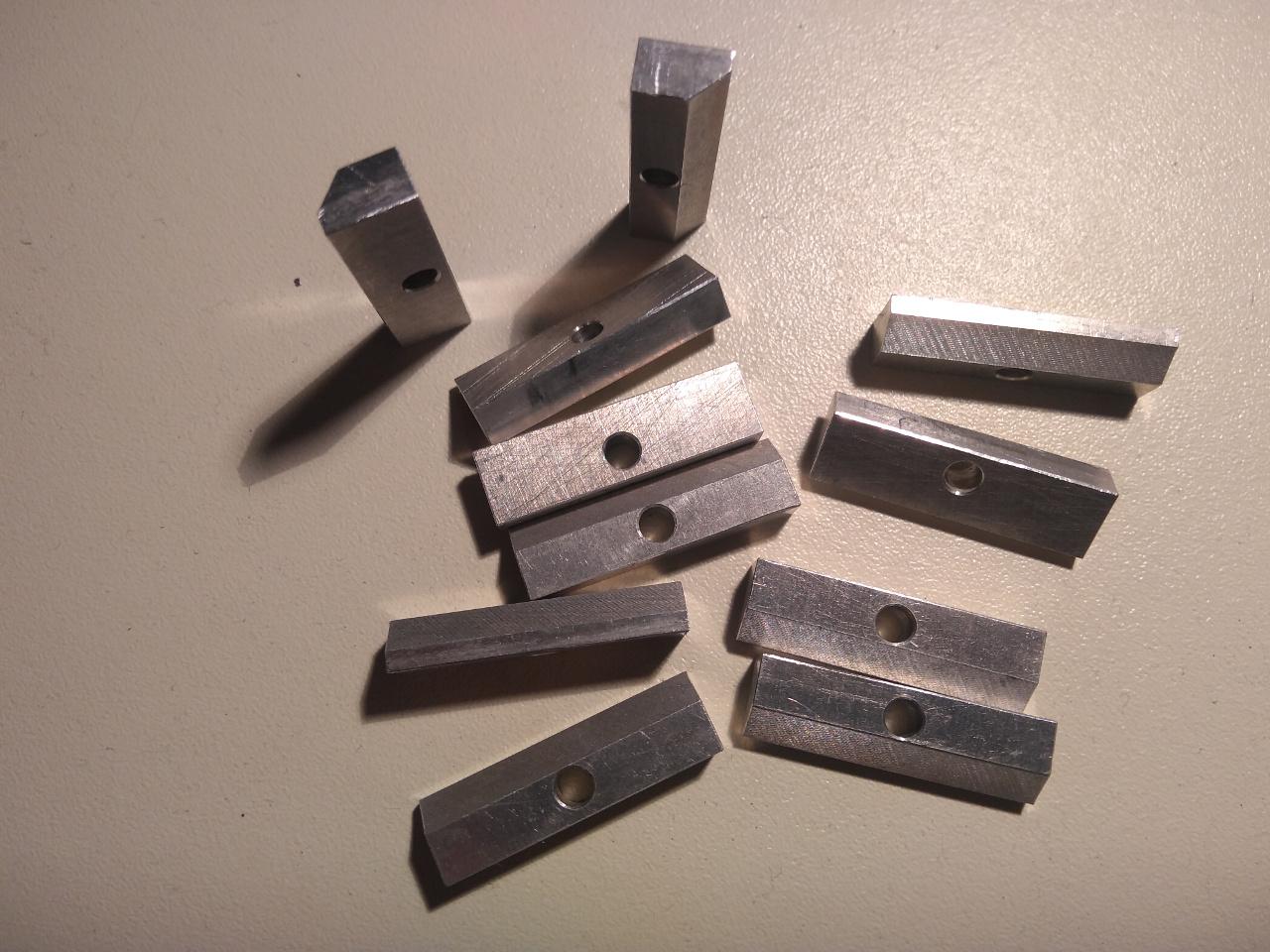
It makes a huge difference! 5 watts into a dummy load for over 30 minutes no problem. The maximum temperature was a slowing climb to 48 degrees C after which it leveled off. Pointing a fan at the case and blowing air across it caused the temperature to fall back down to 40 degrees and was still slowly dropping.
73,
Jayson
AA7NM
Steve Haynal
Winston and Jayson, glad your heat shims arrived and that Jayson's works well. I had to drill the hole in mine slightly larger for it to fit in the case as it could not be pushed close enough to the outside edge. . It was close to other components. I used thermal paste so very thin interface. I'd appreciate feedback from testers on any changes to make it fit better. I will send an updated drawing to Makerfabs as they agreed to include this in future orders. Unfortunately, I don't think they will modify the enclosure.

Probir
You received this message because you are subscribed to the Google Groups "Hermes-Lite" group.
To unsubscribe from this group and stop receiving emails from it, send an email to hermes-lite...@googlegroups.com.
Chris Gerber
--
You received this message because you are subscribed to the Google Groups "Hermes-Lite" group.
To unsubscribe from this group and stop receiving emails from it, send an email to hermes-lite...@googlegroups.com.
To view this discussion on the web visit https://groups.google.com/d/msgid/hermes-lite/65c0d209-333e-48e8-a328-b27daf3cb66co%40googlegroups.com.
Samir, OD5SK
keyboa...@gmail.com
the fit was EXTREMELY tight in that space. The HL board now pushes
against the top of the groove and in fact didn't fit initially as I'd
tried adding a bit of solder along the top board edge in an attempt to
improve coupling. Removed and it's fine.
I set the board in the groove enough to slide the shim between the board
and the case underneath the finals and then slid them together down to
the case hole using a toothpick though their holes. That kept from
having any pressure against components by the shim as it moved into place.
The case hole was hand measured and drilled (not currently countersunk)
and while the standard M3 screw was able to get all the way through it's
tight through the hole and I couldn't tighten it down until the end
plates were set and HL2 and the N2ADR filter board aligned in the case
properly. After that it's a solid sandwich. Thermal compound is
naturally a very thin layer.
I guess I now appreciate the hesitancy on consulting other maker
machinists to craft something like this by description alone. The
tolerances are extremely tight. You might consider shaving a few
micrometers in thickness.
The improvement in thermal equilibrium is tremendous. The duty cycle is
100%. It's slower to heat and levels off well below cutoff. Cools
quickly. A variety of external cooling could be applied to the case. Peltier Junction anyone?
Reading the Hermes wiki and development history is a bit like coming
across a great series in a later season and trying to binge back bits to
understand how things came to be the way they are now. My perspective is
jumbled but the story's gotten better over time. Keep up the great
work!
73,
Jayson
AA7NM
Steve Haynal
Steve Haynal
Samir Khayat
You received this message because you are subscribed to a topic in the Google Groups "Hermes-Lite" group.
To unsubscribe from this topic, visit https://groups.google.com/d/topic/hermes-lite/ePG9rzab3BM/unsubscribe.
To unsubscribe from this group and all its topics, send an email to hermes-lite...@googlegroups.com.
To view this discussion on the web visit https://groups.google.com/d/msgid/hermes-lite/ebbe339f-97b3-4798-81db-3d25807458cbo%40googlegroups.com.
Probir

rhqq2yxrkt
Thermal compounds / heat sink compounds have a specification watts per meter Kelvin w/mk. The higher the number the greater the heat
transference or heat coupling.
John G3UGY
Steve Haynal
To unsubscribe from this group and stop receiving emails from it, send an email to hermes-lite+unsubscribe@googlegroups.com.
ron.ni...@gmail.com
Steve Haynal
Winston
Chris Gerber
HL2 Shim Mounting Instruction for 40mm Enclosure
Chris HB9BDM
Step
1: Place
the Hermes and Filter board in correct position and drill then
a
3.5mm hole, according to former instructions.
Step 2: Use sandpaper to grind of the coating at the bottom of the enclosure,
also the shoulder part of the rail. This will assure good thermal contact.
Then coat the places with Thermal compound, also the Rail Shoulder and side.
Step3: Pic1, Positioning the enclosure accordingly.
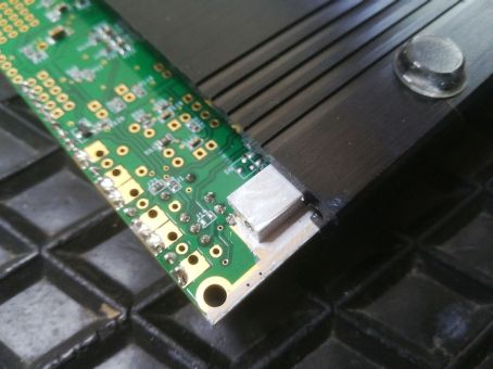
Pic1
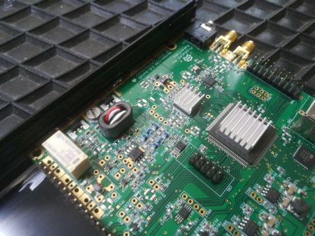
Step 4: Pic2, Check thickness of the shim, it should be 5.00mm or 0.1mm less.
Coat the board surface where the shim is placed also with Thermal compound.
Place the shim between board and enclosure, so it still sticks out (Pic1)
Narrower side of shim facing board, wider side of shim facing enclosure.
Turn the enclosure together with the board, shim in-between carefully around
(Pic2)
and use the 3mm mounting screw to hold shim in place during
the sliding
in procedure, till you reach the mounting whole position.

Pic2
Step
5: Pic3 carefully
remove the mounting screw and insert form the bottom
of the enclosure. Secure with washer and nut, but don’t tighten.
Pic3
Step
6: Connect Hermes and Filter Boards. Then press the whole
assembly fully onto
the
side, to ensure a good thermal contact with the side of the
enclosure. Then tighten
the 3mm screw. That concludes the job.
ron.ni...@gmail.com
ron.ni...@gmail.com
Chris Gerber
--
You received this message because you are subscribed to the Google Groups "Hermes-Lite" group.
To unsubscribe from this group and stop receiving emails from it, send an email to hermes-lite...@googlegroups.com.
To view this discussion on the web visit https://groups.google.com/d/msgid/hermes-lite/816b5fa7-1a70-4662-8c2e-00bb99370a55n%40googlegroups.com.