UltiCore
1,070 views
Skip to first unread message

Ryan Carlyle
Jul 10, 2014, 4:28:31 PM7/10/14
to 3dp-...@googlegroups.com
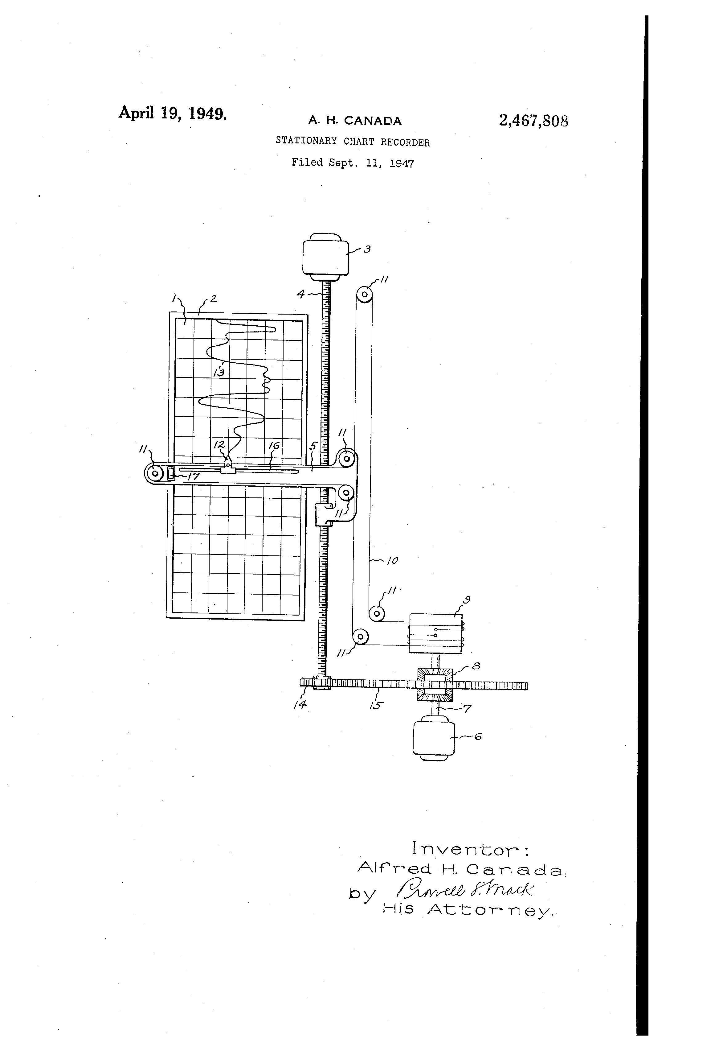
UltiCore is a hybrid gantry between Ultimaker and CoreXY. It uses an Ultimaker-style crossed gantry, but has a diagonal-transform motion mechanism similar to Hbot or CoreXY. This is high on my to-do list since it's a relatively straightforward conversion from CoreXY. Here's the "half belt path" that controls one diagonal axis of motion:

You would use two of these belts (rotated 90 degrees apart) to construct a full XY gantry. Kinematics are identical to CoreXY except the steps/mm value is doubled due to the pulley arrangement. The corresponding top speed reduction can be eliminated by doubling the motor pulley size or switching to 1/8th microstepping.
Since Ultimakers already use a parallel Cartesian gantry (no moving motors), there is no real moving mass improvement. There are a few advantages though:
- Motive force is now applied directly to the XY carriage as well as the X & Y ends, meaning the rods do not need to directly push the carriage. That, in turn, reduces rod flex and non-linear carriage twist during acceleration and deceleration.
- Very friendly design for spectra line, allowing reduced parts cost versus GT2 components
- No need for torsion rods or doubled motors to sync opposite sides together
- Easy gantry alignment (via tension like CoreXY)
Advantages versus CoreXY:
- All endstops can be stationary
- X and Y are symmetrical, which makes acceleration tuning simpler (since current CoreXY firmware applies acceleration to A/B diagonal axes and thus does not allow different X and Y acceleration despite different moving masses)
Downsides:
- Needs 16 pulleys
- Arguably more complex than either Ultimaker or CoreXY gantries
- Carriage carries more hardware than Ultimaker
- 2 extra rods vs CoreXY
- 2:1 motion reduction & associated offset via pulley size or microstepping may be undesirable for high speed printers
Of course, I have yet to build the thing and it might have other downsides.

Whosa whatsis
Jan 7, 2015, 10:31:45 PM1/7/15
to 3dp-...@googlegroups.com
I like the idea, but why not just end the belts at the effector? I find that trying to double resolution by looping belts that way just increases the accumulated error, and more parts means more failure modes, not to mention the mass of all those pulleys you need to carry around.
The racking forces are harder to picture. Obviously uneven tension of the two belts would skew the gantry, but I'll have to sit down when I have a little more time to map out the forces and how they balance in the worst-case scenarios.
Ryan Carlyle
Jan 8, 2015, 3:07:51 PM1/8/15
to 3dp-...@googlegroups.com
Looping the belts ensures drive force is applied evenly to all the X and Y carriages and the effector. If you terminate the belts at the effector without the loop-back, you've either reinvented CoreXY, or have extremely unbalanced racking forces (depending on which orientation you use for the belt paths).
whosawhatsis
Jan 13, 2015, 2:46:03 PM1/13/15
to Ryan Carlyle, 3dp-...@googlegroups.com
Ok, how about this one. What if you did a mashup of an H-bot or coreXY with a discrete replicator-style Y axis. That is, Y axis is driven normally, with Y belts attached only to the ends of the X axis rods/beam, and the X axis belt was routed in a T or P shape so that it ran like an h-bot/coreXY axis.
To move in the Y direction, you send the steps to both motors (with the right belt path, probably the T configuration, this could give you a little extra power for moving the heavier Y axis), while moving the X axis steps only that motor. This would make both motors stationary with a minimum of extra pulleys and a very simple belt path compared to CoreXY.
On Thursday, January 8, 2015 at 12:07 PM, Ryan Carlyle wrote:
Looping the belts ensures drive force is applied evenly to all the X and Y carriages and the effector. If you terminate the belts at the effector without the loop-back, you've either reinvented CoreXY, or have extremely unbalanced racking forces (depending on which orientation you use for the belt paths).
--You received this message because you are subscribed to a topic in the Google Groups "3DP Ideas" group.To unsubscribe from this topic, visit https://groups.google.com/d/topic/3dp-ideas/FE9b4t0d_tQ/unsubscribe.To unsubscribe from this group and all its topics, send an email to 3dp-ideas+...@googlegroups.com.To post to this group, send email to 3dp-...@googlegroups.com.To view this discussion on the web visit https://groups.google.com/d/msgid/3dp-ideas/7803ddcd-a9ea-4ae5-badf-00702bd3af85%40googlegroups.com.For more options, visit https://groups.google.com/d/optout.
Ryan Carlyle
Jan 13, 2015, 6:21:29 PM1/13/15
to 3dp-...@googlegroups.com
Are you describing the "CoreXE" concept some peeps came up with a while back? See:
https://groups.google.com/forum/m/#!topic/3dp-ideas/Xv-tC_bf708
https://groups.google.com/forum/m/#!topic/3dp-ideas/Xv-tC_bf708
whosawhatsis
Jan 13, 2015, 7:47:14 PM1/13/15
to Ryan Carlyle, 3dp-...@googlegroups.com
No, it seem like using a belt like that to drive the extruder would cause racking or worse, with the axis being an almost purely inertial load and the extruder requiring a lot of force. What I'm talking about doesn't involve the extruder at all, just running the moving X axis from a fixed motor by adding the Y steps. Here's a diagram (if the list will let me post it):

On Tuesday, January 13, 2015 at 3:21 PM, Ryan Carlyle wrote:
Are you describing the "CoreXE" concept some peeps came up with a while back? See:
--You received this message because you are subscribed to a topic in the Google Groups "3DP Ideas" group.To unsubscribe from this topic, visit https://groups.google.com/d/topic/3dp-ideas/FE9b4t0d_tQ/unsubscribe.To unsubscribe from this group and all its topics, send an email to 3dp-ideas+...@googlegroups.com.To post to this group, send email to 3dp-...@googlegroups.com.
To view this discussion on the web visit https://groups.google.com/d/msgid/3dp-ideas/215e83c5-d529-4b49-b8cd-411c35dd9abb%40googlegroups.com.
Ryan Carlyle
Jan 13, 2015, 8:38:48 PM1/13/15
to 3dp-...@googlegroups.com
Hmm. Weird kinematics. The actuator axes aren't perpendicular, which is unusual but feasible. It would have "rhombus pixels," which I'm not sure any existing firmwares would like. Let's call it the "Whosa Whatsis Rhombus Drive."

I drew the rhombus tesselation "grid" a bit skewed. The mm/step resolution should be srt(2) times larger on the blue axis so you get a proper rectilinear grid at the intersection points.
whosawhatsis
Jan 13, 2015, 9:02:34 PM1/13/15
to Ryan Carlyle, 3dp-...@googlegroups.com
Yeah, I know. The easiest way to implement it would be to insert it in the stepper driver code, just sending the Y axis steps to both motors so that the steps of the two axes are logically perpendicular with equal resolution. The motor itself would jitter more, but the X carriage's motion might actually be more linear this way than implementing it as two non-perpendicular axes.
--
You received this message because you are subscribed to a topic in the Google Groups "3DP Ideas" group.
To unsubscribe from this topic, visit https://groups.google.com/d/topic/3dp-ideas/FE9b4t0d_tQ/unsubscribe.
To unsubscribe from this group and all its topics, send an email to 3dp-ideas+...@googlegroups.com.
To post to this group, send email to 3dp-...@googlegroups.com.
To view this discussion on the web visit https://groups.google.com/d/msgid/3dp-ideas/732edb95-c936-474d-bbf7-27e1b47daa47%40googlegroups.com.
whosawhatsis
Jan 13, 2015, 9:23:15 PM1/13/15
to Ryan Carlyle, 3dp-...@googlegroups.com
Put another way, you would not move diagonally by only stepping the red motor, you would break up the move into discrete X/Y steps first, so that each move of the X axis is a step of the red motor, and each step on the Y axis is a step of both motors, even if that means that the red motor has to step one way for the X portion of a move and the other way for the Y portion (unless the two are supposed to happen at the exactly the same time, in which case they cancel out). This turns the motion back into a perpendicular cartesian coordinate set, and nothing upstream of the stepper driver pulsing code needs to know about it.
whosawhatsis
Jan 13, 2015, 9:33:25 PM1/13/15
to Ryan Carlyle, 3dp-...@googlegroups.com
In a sense, this does cut the effective resolution of the red in half along its natural travel direction, but I think that bringing the two logical axes back to perpendicular would be worth it in this case, and would result in less jitter (or more acceptable jitter) of the nozzle's path.
CoreXY/H-bot designs could also be implemented this way, and sometimes I think that it would save a lot of hassle, but since their axes are already perpendicular, it's hard to justify the sqrt(2) reduction in print resolution.
Ryan Carlyle
Jan 13, 2015, 10:58:18 PM1/13/15
to 3dp-...@googlegroups.com
The way Sailfish does CoreXY is to calculate the number of motor steps required to achieve the desired Cartesian motion steps:
A = X + Y
B = X - Y
So the motor step count per segment is simply adjusted as above to perform the inverse kinematics. Otherwise, everything is stepped out exactly the same. Surprisingly simple.
GRBL based firmwares can't do direction reversals on motor axes within path segments, so this is the only way to do it in code.
whosawhatsis
Jan 16, 2015, 2:02:05 PM1/16/15
to Ryan Carlyle, 3dp-...@googlegroups.com
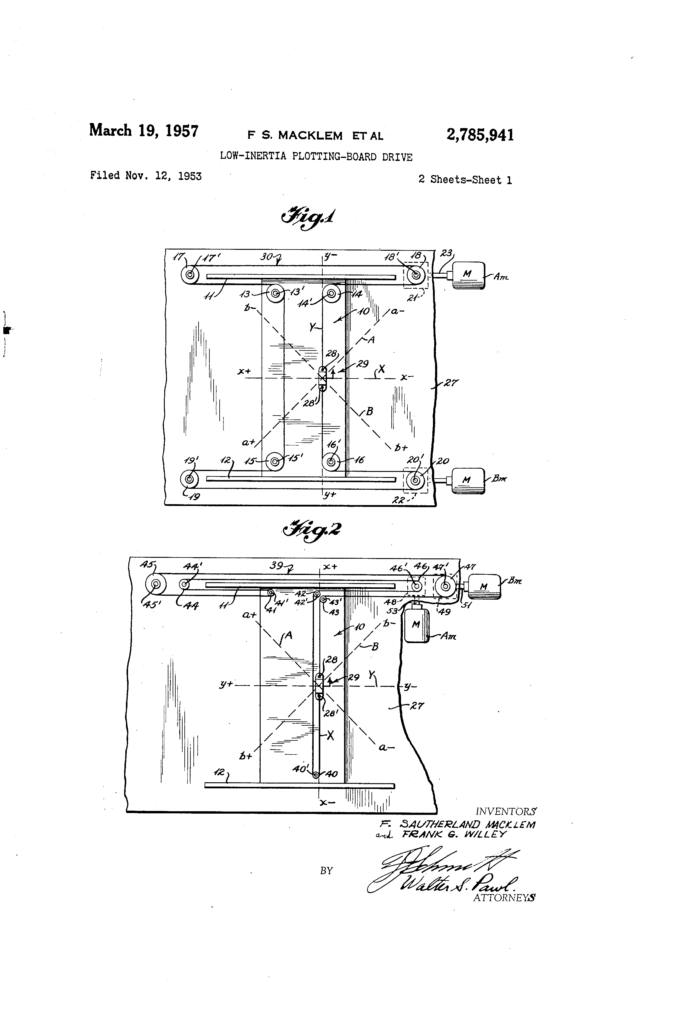
Ok, here's a really crazy idea, what if we turned the Y rods 45 degrees? There would have to be something a little more complicated than a torsion rod to keep the two belts in sync, but that should make the coordinate system square again, while making the build space rhombic. This would have the additional advantage that making the X and Y rods meet at a 45 degree angle should make it more resistant to racking, as any rotation of the X rod would immediately turn into lateral force on the Y axis bearings (I've actually considered doing an H-bot or CoreXY with an angled X axis support for just this reason). Of course squaring the machine in the first place wouldn't be easy, and failing to do so would result in heritable error...
--You received this message because you are subscribed to a topic in the Google Groups "3DP Ideas" group.To unsubscribe from this topic, visit https://groups.google.com/d/topic/3dp-ideas/FE9b4t0d_tQ/unsubscribe.To unsubscribe from this group and all its topics, send an email to 3dp-ideas+...@googlegroups.com.To post to this group, send email to 3dp-...@googlegroups.com.
To view this discussion on the web visit https://groups.google.com/d/msgid/3dp-ideas/8cde1b65-bb50-450b-b072-3d6879c4d21c%40googlegroups.com.
Ryan Carlyle
Jan 16, 2015, 4:19:38 PM1/16/15
to 3dp-...@googlegroups.com
Hmm, interesting. Would the pixels be square or 1:sqrt(2) ratio if you did that?
whosawhatsis
Jan 16, 2015, 5:52:14 PM1/16/15
to Ryan Carlyle, 3dp-...@googlegroups.com
Actually, with the X belt running along the diagonal Y rails, the axes wouldn't be square with a 45 degree angle. It made more sense when it came to me last night as I was falling asleep. The coordinates work out to the following:
Y = B * cos(a)
X = R + Y * (tan(a) - cos(a))
So in order for the coordinate system to be square, tan(a) must equal cos(a), which happens at about 38.17 degrees, which is even worse than the 45 degree angle in terms of the difficulty of aligning the axes. With this value, it simplifies to this:
Y = B * cos(38.17) = B * .7862
X = R
This would work, with a rhombic work area 38.17 degrees from square, or you could use a square build area with a little over 1/5 of your X travel outside the plate, which might be useful for park/dump areas, but it's not as clean as (though it is a bit closer to square than) the 45 degree solution (which would require the X motor to ride the X component of the skewed Y axis's movement). It's probably less useful than the original idea with square axes and differential drive for X.
On Friday, January 16, 2015 at 1:19 PM, Ryan Carlyle wrote:
Hmm, interesting. Would the pixels be square or 1:sqrt(2) ratio if you did that?
--You received this message because you are subscribed to a topic in the Google Groups "3DP Ideas" group.To unsubscribe from this topic, visit https://groups.google.com/d/topic/3dp-ideas/FE9b4t0d_tQ/unsubscribe.To unsubscribe from this group and all its topics, send an email to 3dp-ideas+...@googlegroups.com.To post to this group, send email to 3dp-...@googlegroups.com.
To view this discussion on the web visit https://groups.google.com/d/msgid/3dp-ideas/6e196430-47f7-44fb-9bfd-ccdd2e422604%40googlegroups.com.
Ryan Carlyle
Jan 16, 2015, 7:52:01 PM1/16/15
to 3dp-...@googlegroups.com
Sounds like it's rapidly getting more complicated than the benefits merit... But it would be fun to build :-)
whosawhatsis
Jan 16, 2015, 8:59:42 PM1/16/15
to Ryan Carlyle, 3dp-...@googlegroups.com
Yeah, beginning to sound like something that Nicholas Seaward would build :P
I still like the idea of doing the compensation at "step time" though. It has the advantage that none of the other kinematics are playing tricks there, so there shouldn't be as much weird code to dig through to find where to add my one or two lines in an ifdef.
On Friday, January 16, 2015 at 4:52 PM, Ryan Carlyle wrote:
Sounds like it's rapidly getting more complicated than the benefits merit... But it would be fun to build :-)
--You received this message because you are subscribed to a topic in the Google Groups "3DP Ideas" group.To unsubscribe from this topic, visit https://groups.google.com/d/topic/3dp-ideas/FE9b4t0d_tQ/unsubscribe.To unsubscribe from this group and all its topics, send an email to 3dp-ideas+...@googlegroups.com.To post to this group, send email to 3dp-...@googlegroups.com.
To view this discussion on the web visit https://groups.google.com/d/msgid/3dp-ideas/742a101b-f10a-4962-a19e-47294d5a762d%40googlegroups.com.
whosawhatsis
Apr 11, 2015, 3:42:05 PM4/11/15
to Ryan Carlyle, 3dp-...@googlegroups.com
I did some checking, and this will be easy to implement with Smoothie, though it won't get the step-adding behavior I really want...
whosawhatsis
Apr 11, 2015, 3:54:44 PM4/11/15
to Ryan Carlyle, 3dp-...@googlegroups.com
Which, BTW, also means that it gets the sqrt(2) resolution increase from CoreXY.
Ryan Carlyle
Apr 11, 2015, 4:24:34 PM4/11/15
to 3dp-...@googlegroups.com
You wanna put together a diagram of what you're thinking now? I've lost my train of thought on what this looks like.
Would it just use the "rotated Cartesian" Smoothie robot module, or a new module?
On Saturday, April 11, 2015 at 2:54:44 PM UTC-5, Whosa whatsis wrote:
Which, BTW, also means that it gets the sqrt(2) resolution increase from CoreXY.On Saturday, April 11, 2015 at 12:42, whosawhatsis wrote:
I did some checking, and this will be easy to implement with Smoothie, though it won't get the step-adding behavior I really want...On Friday, January 16, 2015 at 17:59, whosawhatsis wrote:
Yeah, beginning to sound like something that Nicholas Seaward would build :PI still like the idea of doing the compensation at "step time" though. It has the advantage that none of the other kinematics are playing tricks there, so there shouldn't be as much weird code to dig through to find where to add my one or two lines in an ifdef.On Friday, January 16, 2015 at 4:52 PM, Ryan Carlyle wrote:
Sounds like it's rapidly getting more complicated than the benefits merit... But it would be fun to build :-)--You received this message because you are subscribed to a topic in the Google Groups "3DP Ideas" group.To unsubscribe from this topic, visit https://groups.google.com/d/topic/3dp-ideas/FE9b4t0d_tQ/unsubscribe.
To unsubscribe from this group and all its topics, send an email to 3dp-ideas+unsubscribe@googlegroups.com.
whosawhatsis
Apr 11, 2015, 5:25:03 PM4/11/15
to Ryan Carlyle, 3dp-...@googlegroups.com
The original rhombic one. Arm solution definitions in Smoothie look like this: https://github.com/Smoothieware/Smoothieware/blob/edge/src/modules/robot/arm_solutions/HBotSolution.cpp#L4
That would make it easy to make one that is straight, and the other at 45 degrees to it with a scaling factor.
You received this message because you are subscribed to the Google Groups "3DP Ideas" group.
To unsubscribe from this group and stop receiving emails from it, send an email to 3dp-ideas+...@googlegroups.com.
To view this discussion on the web visit https://groups.google.com/d/msgid/3dp-ideas/b8367ee3-413d-44a7-9077-11d680167c8b%40googlegroups.com.
Whosa whatsis
Jul 15, 2015, 2:51:56 AM7/15/15
to 3dp-...@googlegroups.com, temp...@gmail.com
Now I'm thinking about two T-shaped belt runs, one laid over the other. The X carriage would attach to one of these belts on the front pass, and the other on the back pass, giving it regular hbot/corexy kinematics with resistance to racking while still allowing it to be cantilevered for a simplified frame. For a larger version that needs the un-driven end of the X axis supported and its inertia and friction become a factor, I'm thinking about using a cable drive, like one of the dualwire axes but without a motor attached, to passively keep the two ends in sync. This one will be hard to depict in a 2D diagram, so I'll have to put some stuff in CAD to show what I mean.
Ryan Carlyle
Nov 27, 2015, 2:12:46 AM11/27/15
to 3DP Ideas, temp...@gmail.com
Check these out:
Reply all
Reply to author
Forward
0 new messages