H-Lv2b2 PA mesurements

in3otd
Hello,
I've done some measurements on the H-L v2b2 PA output;
here is the PA output vs. the TxPGA gain (controlled using the Spot value in Quisk):

results are quite similar to the stand-alone PA measured here. As known, the full driver output is not needed to have 37 dBm (5 W) out, so the PA is overdriven when using the maximum gain settings.
Next graph is the PA efficiency, same conditions as above:

Last graph is the fundamental and first few harmonics output for TxPGA gain setting of 8, which gives (more than) 5 W out up to 30 MHz:

All the above data were taken with the PA output transformer center tap connected to the on-board 9.4 V supply via a current meter, so the actual results for the usual case when the center tap is soldered directly to the power supply may be slightly different.
I need to check how well output transformer works at low frequency, I recall it got more than warm at full power at 1.8 MHz on the test PA.
73 de Claudio, IN3OTD / DK1CG

Graeme Jury
Many thanks for the hugely useful graphs and information. I am interested to know which version of the PA you are using for the tests i.e. which transistors etc. I note that the amplifier will be run at more than +37 in the final system and probably at around +38 dBm depending on the filter board losses. In my own case my filter board is going to be the same size as the full size V2 HL board (the size with the tabs on) and will have the Rx and Tx filters on the board with M7 diodes switching the Tx and PE4259's switching the Rx filters so the losses will be higher than with relays but your graphs show there will be no problem with power and Quisk allows equalization by band as I expect other radios will too so I am unlikely to need to go higher than step 12 even at 30 MHz.
I really appreciate the work you are doing in this area and your whole web site data is a goldmine.
73, Graeme ZL2APV

John Williams
Graeme,
Will be anxious to follow your progress...
John
--
You received this message because you are subscribed to the Google Groups "Hermes-Lite" group.
To unsubscribe from this group and stop receiving emails from it, send an email to hermes-lite...@googlegroups.com.
For more options, visit https://groups.google.com/d/optout.

Steve Haynal
in3otd
How hot were the AFT devices when you were running around 10W output?
Do you think heat can be properly dissipated at that level?

The datasheet says that the device thermal resistance, junction to case, is 4.1 °C/W so if we were able to keep the devices case at room temperature the junctions temperature will rise just by 13 degrees. Equivalently, we can say that if we allow a junction temperature increase of 100 °C (a bit extreme, but the junction temperature can go up to 150 °C, with a lower MTBF) the overall thermal resistance can be almost 31 °C/W, leaving more than 26 °C/W for the case-to-ambient part. Of course this will leave no margin for increased power dissipation due to bad SWR and does not take into account the other heat sources in the H-Lv2 but we should be able to reach quite less than 26 °C/W of case-to-ambient thermal resistance. "How?" is the part that needs to be figured out, hi. I'll open another thread for the H-Lv2 thermal management.
Are the harmonics relatively worse at 10W versus 5W?

I've been experimenting with various tweaks to the PA and driver. First, I've been using separate power supplies for the driver and the PA. U12 has been powering the driver after cutting the trace to pin 8 and connecting that to DB10 pin 1. R91=11.5K and R102=1.6K produces 10.15V. U8 is powering the PA with R19=16.2K and R46=1.8K for 7.9V. Second, I've reduced the gain of the driver by setting R55 to 120 Ohms. I see max output at the low power output of ~17dBm and the PA never goes higher than 39dBm with full TxDAC drive.I'm considering on finalizing on one of these options for an assembled run. I'd appreciate your input on what you think is best.
As usual, the best option depends of the definition of "best"... Option 4 if you'd like to go for the lowest cost; Option 3 IMHO is the best overall since it will suit both people wanting an (almost) ready made RTX and those wanting to experiment a bit and fit the RD15 HVF1 PA. Removing SMD components is easier than solder them, hi, and even if some traces/pads are lifted around the on-board PA while reworking it, it should be not too difficult to repair as all the connections are on the outer layers.
I'm not sure I agree with all the points listed for Option 1 and 2 regarding efficiency and power dissipation, need to think more about that.
Steve Haynal

James Ahlstrom
On Monday, March 13, 2017 at 1:04:18 AM UTC-4, Steve Haynal wrote:
I'm considering on finalizing on one of these options for an assembled run. I'd appreciate your input on what you think is best.Option 1:
Steve Haynal
Steve Haynal
James Ahlstrom
On Monday, March 13, 2017 at 1:04:18 AM UTC-4, Steve Haynal wrote:
I'm considering on finalizing on one of these options for an assembled run. I'd appreciate your input on what you think is best.
James Ahlstrom
On Monday, March 13, 2017 at 1:04:18 AM UTC-4, Steve Haynal wrote:
Second, I've reduced the gain of the driver by setting R55 to 120 Ohms. I see max output at the low power output of ~17dBm and the PA never goes higher than 39dBm with full TxDAC drive.
Graeme Jury
If the goal is to get 5 watts out of the HL2 then it should include the filters also. For a straight relay switched LP filter the loss would be typically .3 dBm and the 120 ohm resistor would be fine. If however solid state filter switching and antenna changeover is utilised we would be looking at a total loss of typically 1 dBm and would require 6.3 watts out to meet this so the 100 ohm resistor would be a good choice in this case with a little headroom as well.
Using Quisk with my HiQSDR I am using Tx Levels of around 120 to drive my amplifier to 100 watts and consider setting the level which does not cause spurs to be a mandatory setup requirement although I appreciate some users will not see it that way and go for as much power as they can get and we need to protect the community from them by limiting the output to the linear capability of the finals.
There seems to be a trend to using the AFT05's but it seems to me that many of the problems they suffer like getting rid of heat and running right at maximum power would simply go away with TO220 fets. I am wondering if the AFT's offer some big advantage I don't see?
73, Graeme zl2apv
James Ahlstrom
in3otd
some solutions for this were discussed in another thread, see e.g. here. Having finer steps for the bias is certainly a good thing, even if maybe not so important for the RF performances; at least we will use the full potentiometers range and the users would not wonder why nothing happens over most of the range, hi.
73 de Claudio, IN3OTD / DK1CG
in3otd
I agree it would be nice to have 5 W after the TX filters; IIRC we didn't find a cheap diode working well as TX switch down to 1.8 MHz and I tend to think that relays may be more suited here.
I think that the major advantages of the AFT05MS003N devices are the low cost and the fact that they are SMDs so they can be assembled on the board with the other components. The heat dissipation seems not to be a major problem at present, at least for SSB usage.
The PA with the RD15HVF1 I tried (see unfinished page here) could provide some more power but the gain vs. frequency variation was quite higher.
73 de Claudio, IN3OTD / DK1CG
Graeme Jury
The diodes were a bit disappointing at 1.8 MHz except for the M7 which may be brand dependent and the ones I have here work quite well. I am mindful that some may want to work the LF bands and would need to be switching through relays for that although probably would have a separate filter board for that purpose.
Another issue somewhat loosely related to power output and measurements is should a changeover relay be incorporated onto the filter board or should the Rx and Tx ports be brought out on their own sma connectors together with the changeover relay signal? If the input of any following linear is separate Tx and Rx and output from HL was single connector from a changeover relay then a relay would need to be added to switch the Linear inputs and of course if it was a single Rx/Tx input Linear with HL being separate Tx and Rx we have the same issue. None of these are show stoppers but need to be considered as well as on board strapping options together with the inclusion of the relay or not.
I have built a few amplifiers in the 5 watt bracket using SOT-89 packages and getting rid of heat was always a headache for me. I finally got one going that did not thermally destruct by soldering a strip of copper foil as used for repousse work and dressing it to the side of the case and clamping it with some 4mm thick aluminium bar - hence my hesitancy but I am encouraged by the great results you guys are getting and am not so fearful now. Your reasons for the AFT05MS003N's are valid and really good ones.
73, Graeme zl2apv
in3otd
regarding the TX output variation with frequency, currently there is about 1 dB of ripple in the output level due to the filter at the TxDAC output; would it make sense to (try to) modify the filter to have less ripple or even a flat response in the passband?. IIRC, the main driver for the current filter response was to reduce the image at fs-ftx when transmitting in the 10 m band, now that fs is a little higher we could maybe afford a filter with slightly less rejection there.
73 de Claudio, IN3OTD / DK1CG
James Ahlstrom
On Tuesday, March 21, 2017 at 5:32:54 PM UTC-4, in3otd wrote:
Hello Jim,
regarding the TX output variation with frequency, currently there is about 1 dB of ripple in the output level due to the filter at the TxDAC output; would it make sense to (try to) modify the filter to have less ripple or even a flat response in the passband?
Steve Haynal
Steve Haynal
Steve Haynal
James Ahlstrom
John Williams
My Superband design used bandpass. See my PA github clone for the design and values. It was derived from the Peaberry design.
John W9JSW
--
James Ahlstrom
John Williams
Yes, Jim. We have some runs. The issue we had was filter roll-off, mainly due to pcb layout (I was pretty new at it). I reworked the board a few times but never re-ran the filters as we moved on to the all band PA. At this point, I can share the plots with you but think they will confuse the issue, since they were evolutionary. I think it best for you to do a 2 layer simple layout to test them yourself. Should not cost very much to get boards from Elecrow to experiment with. The issue we had with the 2 band approach was due to the single FET PA and suppressing the second harmonic of the lower band. Rolloff was not very sharp. 60/40 and 30/20 were problematic. With a push-pull PA this will be much easier to overcome. We also had issues with the spurs on 12/10M but those have been now resolved.
Some Elsie data attached... If only we can get the real data to
agree with elsie!
John
James Ahlstrom
Graeme Jury
There was a huge amount of work done last year by John, Glenn VK3PE and myself on bandpass filters. As John has pointed out we were working with the constraint of a single ended PA and had difficult requirements to meet for second harmonic suppression. The mesh filters we designed worked well and it may save you a lot of time to review some of the posts we made as we published some performance data.
The bandpass filters will work well and are easy to design with stable and reproducible results with standard components. The reason for moving away from these is to give the flexibility of running a second receiver which may be octaves away and separate hi pass lo pass filters will allow this to occur. It will require a rethink on filter switching from the Quisk etc. perspective as the bandwidth will need a low end and a high end signal and if there are 3 or 4 HP filters they will require a band button each and interlock function so the HP can't be higher than the LP.
As a review perhaps you might like to look at some of the following posts ...
Lo Pass 7 MHz filters - Last few posts most relevant and can be viewed here
30/20 mesh filters - First 10 or so posts and last post and can be viewed here
A collation of mesh filters from Glenn. This is a very important work and should be a big help to you. View it here
An original Elsie design for a 17/15 M mesh filter to test how actual vs Elsie design pans out
The schematic can be seen here and the Elsie plot is here
17M/15M mesh filter as swept by Glenn VK3PE seen here As you can see a pretty good match.
The bandpass filters worked quite well with smd inductors and paid a price of about .5 to 1 dB insertion loss in band only. Out of band the performance was similar to toroids but with 5 watts TX I would be strongly leaning to T37's. We did find that the design was not too critical and winding the toroids to the stated number of turns gave a quite close result so there was really only the tedium of winding them and no requirement for a well equipped lab to adjust after after building the filter.
I still lean to separate HP/LP filters and my experiments suggest that LP needs 160, 80, 60/40, 30/20, 17/15. I would leave the 30 MHz LP filter in circuit as it is easy to design for low insertion loss and low SWR. The HP filters need 160, 80, 40, 30 17. Again I would leave 160 in circuit as a floor filter and switch the other 4 filters. These are the filters which work best for me but may not be the general case as I have very strong broadcast on both AM and 80 MHz FM giving volts on my antenna.
I believe it is important that we agree on what the filtering is so that it can be worked on in unison as John, Glenn and I did. Together we made progress as a team that we never would have done in a sensible time frame individually. As the board is an add on other versions beside the official one can grow although they will be constrained by the signals from the radio software. I don't really care what the official design is as I will work on it until it is completed and if it is not meeting my needs I will simply do my own version later.
73, Graeme zl2apv

pascal.v...@gmail.com
Qrp-labs offers BPF https://www.qrp-labs.com/bpfkit.html - I tried one but probably not well adjusted, I got a 3dB loss that didn't allow to use it to transmit.
Best 73
James Ahlstrom
James Ahlstrom
Steve Haynal
Graeme Jury
Thanks for the info on the AFT05s and yes I am convinced that they will do the job just fine now. The thinking behind the microcontroller is that it will do the job of the 2 I2C bus expander chips in a single chip. As I was considering using PE4259's on Rx and M7 diodes on Tx, the microcontroller would switch them directly and no relay driver like ULN2003 would be needed so nearly all the board real estate would be available for filtering. I was also looking to produce the auxilliary output for a following linear including the PA bias control and TX/RX relay switching signals and was going to program the appropriate delays in the micro. Don't worry too much about this filter board as it is my personal design (although I will of course share it) and I will put my initial effort into the filter design that the group agrees on. I also like Jim's idea of a beginners filter with 3 bands or so and through hole parts. I agree that as high density surface mount board would seem formidable to an inexperienced constructor.
73, Graeme zl2apv
Steve Haynal
Graeme Jury
Here is a typical smd inductor as used in John's board and tested by Glenn. I have run 10 watts through these and they did not fry but I would not use them myself in Tx service without a lot more testing for things like through loss, IMD, heat etc. They work fine in Rx service and the extra loss over toroids can't be heard in practice but can be seen in Tx service.
73, Graeme zl2apv
Steve Haynal
Graeme Jury
73, Graeme zl2apv

Sid Boyce
and the IO Pi Plus board (2x MCP23017's) base for pihpsdr used with HL
v1.44 and John's 5W PA.
John provided the OC config for the filter switching.
I currently only have the 600 PPR VFO encoder connected and working OK.
In a few days I plan to wire in the other encoders and the switches.
Steve is evaluating the new Asus Tinker Board which if as advertised has
the same GPIO configuration as the Pi 3, would be a drop in replacement.
The goal is a compact rig based on HL v2.0.
73 ... Sid.
--
Sid Boyce ... Hamradio License G3VBV, Licensed Private Pilot
Emeritus IBM/Amdahl Mainframes and Sun/Fujitsu Servers Tech Support
Senior Staff Specialist, Cricket Coach
Microsoft Windows Free Zone - Linux used for all Computing Tasks
in3otd
I initially thought that the PA power dissipation would
not be so much different between a 7.5 V and a 9 V supply but then I did
some measurements to have some actual data and indeed there is a big
difference, as you suspected.
I cut the VPA supply trace and used an external power supply to provide different voltages; I run some tests at 9 V and 7.5 V;
here is the power dissipation at 9 V vs. the TxPGA setting (similar to what posted before but not identical, see below)

and here is the power dissipation at 7.5 V, still vs. the TxPGA setting

For a power output around 37 dBm, a 7.5 V supply gives about 2 W less power dissipation! I double checked the calculations since I thought I did some mistake, hi.
This gives some ideas for the H-L v3: the VPA DC/DC converter output level could be controlled by the FPGA, so that when the drive level is lowered the PA (and driver) supply is lowered too and 9 V are used only for the max drive level. Maybe no real DAC/potentiometer could be needed and just some rough delta-sigma modulation of an output pin could be enough to inject an offset into the regulator feedback.
Regarding the output harmonics, the gain at 7.5 V is about 0.5 dB lower maybe also because I did not adjust the bias when changing the PA supply level. So for getting about the same power output, the TxPGA gain level had to be 1 step higher (TxPGA = 8 instead of 7) for the lower supply. Here is the power output for the two supply levels:

output power is practically the same but note that the frequency response is slightly different.
Here are the harmonics levels for the two cases

The higher supply produces less higher-order harmonics, but for the 2nd and 3rd the behavior is less clear.
The harmonics levels (and the power dissipation) vs. frequency are slightly different than the graphs posted previously; one of the reason could be that the previous measurements were done by lifting the PA output transformer center tap and measuring the current there; the tap bypass was done with just a single leaded 100 nF capacitor, while here all the bypass caps are in place as I cut the supply trace near the DC/DC converter.
I'll try do to also some measurements of the PA IMD; as seen before on the test PA, at 7.5 V is usually quite worse than at 9 V.
Steve Haynal
in3otd
Hello,
here is the H-Lv2b2 PA measured IMD vs Pout,
at 7.5 V :

and at 9.0 V supply

the test_PA had a slightly lower IMD at higher power, maybe because the bias current was a little higher there.
BTW, if we will have PureSignal the IMD levels should of course improve quite a bit, even at 7.5 V. Do we need some particular coupling circuitry to have the right input level to the RX for this? I see there is of course quite some leakage from the PA out to the RX but I don't know if it will be enough.
Out of curiosity, I measured also the driver IMD:

I also prefer separate power supplies for driver and PA, seems more flexible - even if a common supply may make sense if we go the "power tracking" supply route.
Having the PA with no drain supply but bias voltage on the gates should not be an issue.
73 de Claudio, IN3OTD / DK1CG
Steve Haynal
in3otd
for all the measurements the driver was supplied by the VPA converter, at about 9.3 V.
Also here the RX clip LEDs are on during TX, when the gain is not too low; I have actually never used PureSignal so I don't know if there are any particular constraints on the feedback level but I agree that if we can get the RX to clip that should be enough, hi.
I missed that there were already CN8/9/10 that could be used for the TXinhibit input; it should be ok even if they are not at the board edge and one has to run a wire to a nearby connector if this feature is needed. One point that's not clear to me is how it should be implemented by default: the TXinhibit pin should be grounded (TX enabled) when this feature is not needed (the majority of users, I think) and brought to a connector when this input is needed. So should we have a 0 ohm jumper to GND that those needing a TXinhibit can remove?
73 de Claudio, IN3OTD / DK1CG
Steve Haynal
KF7O
in3otd
I was just "thinking HW" too much, either polarity will likely be fine. BTW, the Elecraft K3 and KX3 (and maybe others) allow to choose the polarity of the TX Inhibit input, we could also do the same. It might be a bit confusing but I think that as long as the default configuration is "TX enabled" that would be fine. Those needing the TX Inhibit function will have to read the manual, hi.
So in the end, no HW change is likely needed, this function can be assigned to CN8/9/10 by a user configuration and one will have to bring one of these inputs to their connector of choice.
73 de Claudio, IN3OTD / DK1CG
James Ahlstrom
Graeme Jury
Thanks Jim for the post. I am really excited to see your project as I felt that what I am doing would not appeal to all and was going to be difficult to build due to having to use hand wound and calibrated toroids. Having a version which is straight forward is going to be good for the project. I expect other versions will filter out if I may use that expression.
A few comments; I was interested in how the smd inductors turned out for you. I wanted to try them out myself but the inductor values for my filters would not fit the standard smd values. It was difficult enough to manipulate the filter values to get the capacitors to fit. I also ran into the E96 values and voltage limitations and like yourself have had to parallel to keep to 630 volt units. I have ordered most of mine from China so hope they will be OK and will report to the group as I build them up. My intention was to use single pads and piggyback the other caps on top. I have used this method before and it works well even 0805's will piggyback on 1206's.
I have yet to measure the IMD generated from the switching diodes and have gone that way because the filters will need to be switched on the fly if I am transmitting say on 40M band but have the filters set for 80M Hi pass and 20 M Lo pass so I can skim those bands and of course I need to switch in the 40M LPF to transmit.
Steve if you are reading this, I will need some info from you about what is going to happen in the I2C control to the filters but have not bothered you at this stage while you are concentrating on getting beta3 out but when you are clear I will have several questions like will PTT be over I2C and so on.
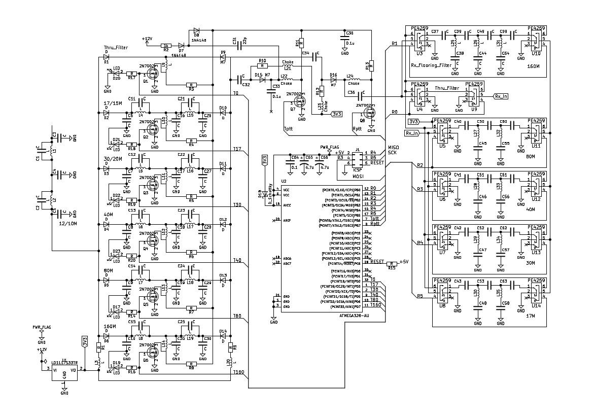
I have included the nearly complete schematic. On the atmega328, A0 to A3 will be for filter control lines and there will be a selection for this or I2C input to enable it to be used with HLv1 or HLv2. Still a long way to go but at least I am now finally home and can get some useful time on it.
73, Graeme zl2apv
James Ahlstrom
On Wednesday, June 14, 2017 at 10:31:47 PM UTC-4, Graeme Jury wrote:
I wanted to try them out myself but the inductor values for my filters would not fit the standard smd values. It was difficult enough to manipulate the filter values to get the capacitors to fit.
James Ahlstrom
A picture of my test fixture is attached. The left SMA uses the variable capacitor and is used to measure Q at variable frequencies. An 1812 inductor is shown. The right SMA uses one of two 1% capacitors and is used for measuring inductance. A toroid is shown. Connections are made by tack soldering. I am getting good results with this setup, except that my 1% 3.9 uH inductor measures 3.6% low. I only have two 1% inductors, but I plan to get more and continue to experiment.
Meanwhile, here is the measured Q of the Bourns 1.0 uH 5% inductor that had high losses in the 10 meter filter.
Freq MHz Q
7.933 52
10.060 50
15.048 35
20.229 23
30.167 13
Other measurements show that the Coilcraft inductors have low Q at lower frequency, and the Bourns are preferred. Both Coilcraft and Bourns are available at Mouser, but not Digikey.
I also discovered that my AADE L/C meter reads higher inductance for lower Q. For example, it measures 4.338 uH for a toroid with high Q. But if I add a 1 ohm resistor in series, it measures 4.545 uH, or +4.8%. The Q with the resistor is 20 at a 750 kHz test frequency. Remember that the AADE measures at 750 kHz or lower, but the test fixture can measure at the operating frequency.
I hope this is useful to someone.
Jim
N2ADR
Steve Haynal
James Ahlstrom
On Saturday, June 17, 2017 at 1:50:21 PM UTC-4, Steve Haynal wrote:
Jim, what are your thoughts on the Bourns SMD inductors for 160M and 80M filters?
Also, I am very interested in how the fwd/rev power works out on your board. I assume you haven't tested that yet as the boards are on order?
any systematic measurements. Where I am going with all this rambling is that I can see the practical value of RX bandpass filters to help with the limited 12-bits of the AD9866 given broadband noise in general, but have yet to see (and want to see) the practical benefits for IM2.
Graeme Jury
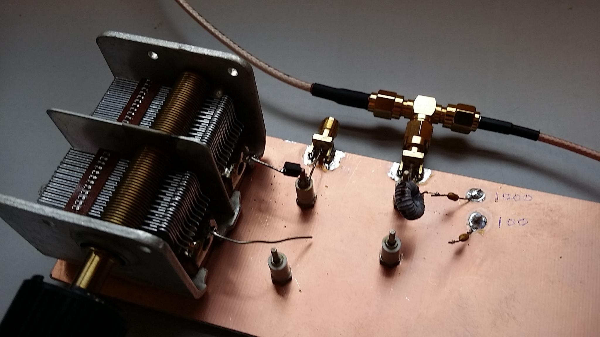
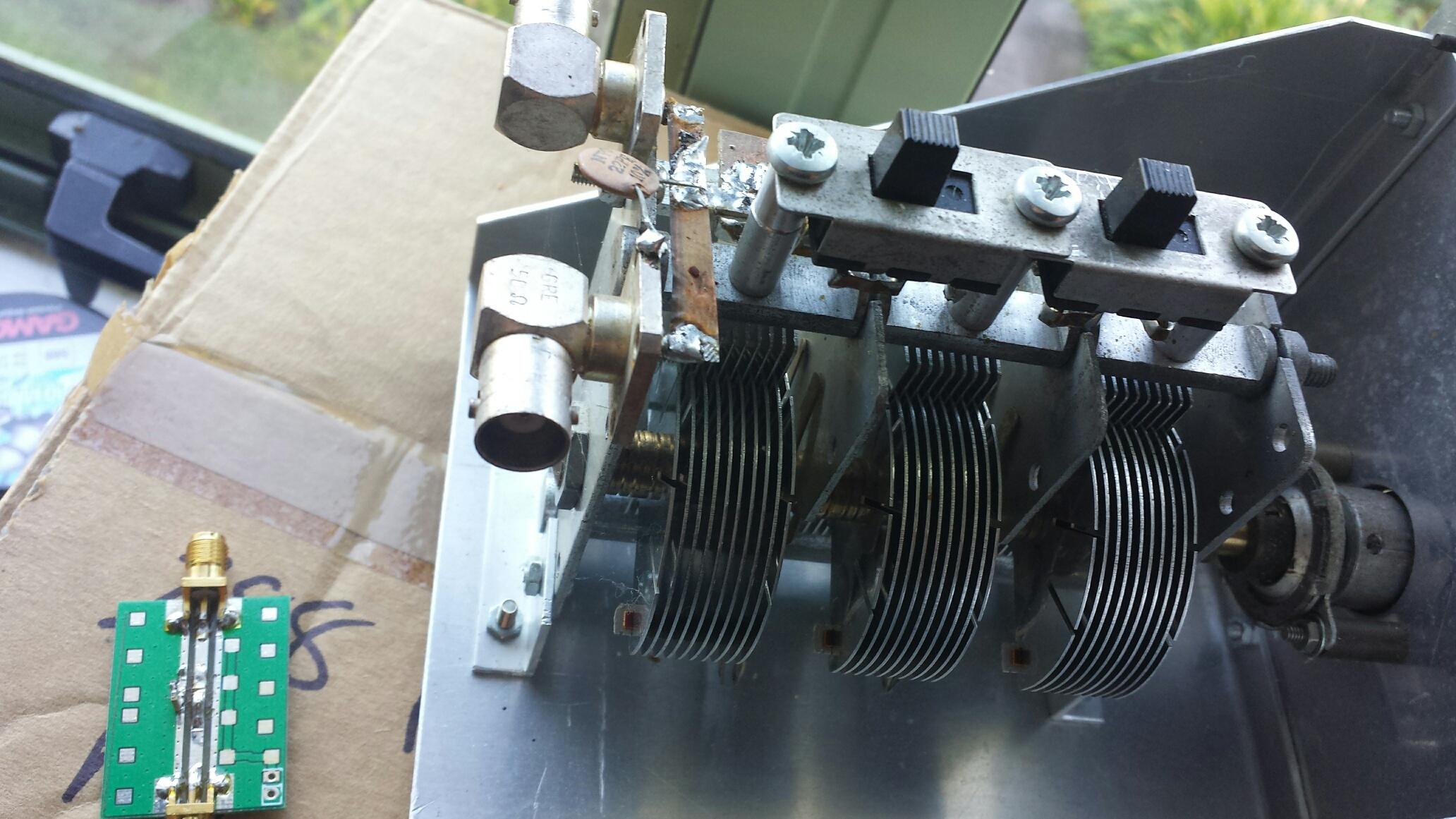
That information is very valuable Jim and in line with what I have found. I wonder if you have come across the spreadsheet done by Jaques Audet VE2AZX available here which can be used in association with his QEX article here. This method is very accurate and shows how toroid inductances vary with frequency etc. I do find a few anomalies but the results are within ham shack experimental range. His whole web site is a mine of information. I use a test jig made from a variable capacitor with 2 bnc connectors and a copper strip soldered between them. The scale of the capacitor is calibrated in pF and the gangs can be switched in or out with slide switches. I previously had a single gang version and this was the best as the larger capacitor introduces some unwanted reactances but is still a useful tool. The best tool for this kind of measurement is a small board made by Claudio which is simply a 50 ohm stripline with a pair of sma connectors each end. I solder a low inductance 150 pF capacitor to ground and connect my inductors to this and the centre of the stripline. I have attached a picture of both units.
73, Graeme ZL2APV
James Ahlstrom
James Ahlstrom

Glenn P
RS-HFIQ project uses SMD inductors in the Tx LPF side. It's a nominal 5W rig though.
For interest, here are the type used:
Glenn - vk3pe
| RS-HFIQ Tx LPF inductor types | |||||||||
| line:- | |||||||||
| 54 | 3 | L2, L7, L8 | FIXED IND 1.8UH 900MA 160 MOHM | BOURNS | CC453232-1R8KL | MOUSER | 652-CC453232-1R8KL | ||
| 59 | 1 | L3 | IND 560NH 460MA 1.1 OHM | ABRACON | AISC-1210-R56J-T | MOUSER | 815-AISC-1210-R56J-T | ||
| 62 | 3 | L4, L5, L10 | IND 270NH 630MA 400 MOHM | ABRACON | AISC-1210-R27J-T | MOUSER | 815-AISC-1210-R27J-T | ||
| 63 | 2 | L6, L11 | IND 180NH 700MA 300 MOHM | ABRACON | AISC-1210-R18J-T | MOUSER | 815-AISC-1210-R18J-T | ||
| 64 | 1 | L9 | IND 470NH 490MA 800 MOHM | ABRACON | AISC-1210-R47J-T | MOUSER | 815-AISC-1210-R47J-T | ||
Glenn P
James Ahlstrom
in3otd
for schematics and BOM see the links at the bottom of this page.
73 de Claudio, IN3OTD / DK1CG
Steve Haynal
Steve Haynal
James Ahlstrom
On Tuesday, June 20, 2017 at 2:18:41 PM UTC-4, Steve Haynal wrote:
The FWD/REV circuit is lifted from the Alex opnHPSDR project. See the Alex manual under the documents link.
James Ahlstrom
On Tuesday, June 20, 2017 at 1:10:54 PM UTC-4, in3otd wrote:
for schematics and BOM see the links at the bottom of this page.
James Ahlstrom
Graeme Jury
The bandpass filters with the smd inductors were on the receive filter board and fed via PE4259 switches which will not withstand 5 watts so I have not tested at power. If you like I can whip the 2.2 uH inductors out and build a 30/20M filter and smoke test it for you. I think I have some suitable 630 volt capacitors as the ones in circuit are 50 volt types which are fine for Rx only.
73 Graeme zl2apv
James Ahlstrom
Graeme Jury
Hello Jim,
With T37 toroids I have run them up to 30 watts successfully but in Chebyshev or Cauer filters only. A possible solution for your smd inductors is to go away from the mesh filters and cascade a Hi/Lo pass filter for your bandpass. The tradeoff is that you will need one extra inductor possibly and unfortunately all the inductors will have different values making it very difficult to juggle filter parameters to get standard inductor values. The capacitors will not be so bad with series or parallel combinations. Electronics is no exception to life - everything is a tradeoff :-)
73, Graeme zl2apv
--
You received this message because you are subscribed to the Google Groups "Hermes-Lite" group.
To unsubscribe from this group and stop receiving emails from it, send an email to hermes-lite...@googlegroups.com.
For more options, visit https://groups.google.com/d/optout.
James Ahlstrom
On Wednesday, June 21, 2017 at 2:41:35 PM UTC-4, Graeme Jury wrote:
The bandpass filters with the smd inductors were on the receive filter board and fed via PE4259 switches which will not withstand 5 watts so I have not tested at power. If you like I can whip the 2.2 uH inductors out and build a 30/20M filter and smoke test it for you. I think I have some suitable 630 volt capacitors as the ones in circuit are 50 volt types which are fine for Rx only.
John Williams
I used bandpass filters borrowed from the Peaberry design in the Superband board. Very small run of cards and never did solve issues with sharpness of the filters as we then moved to the multiband tx board with lpf filters.
--
James Ahlstrom
On Wednesday, June 21, 2017 at 3:52:21 PM UTC-4, Graeme Jury wrote:
A possible solution for your smd inductors is to go away from the mesh filters and cascade a Hi/Lo pass filter for your bandpass.
Graeme Jury
I used the mesh filters Jim but with T37 toroids which I did run run up to 30 watts with no sign of heating but I did not do any IMD testing. I had sent the group a plot from quiskVNA of one of the filters but as far as I know you are the first to try smd inductors in TX mesh filters. I will be doing the same non linearity testing on my Hi/Lo pass filter set as you propose as I am concerned about non linearity from the switching diodes although the testing Claudio did and has published on his web site indicate they will be pretty good.
73, Graeme
Steve Haynal
73,
Steve Haynal
Steve Haynal
James Ahlstrom
On Wednesday, June 21, 2017 at 3:09:30 PM UTC-4, James Ahlstrom wrote:
James Ahlstrom
On Saturday, June 24, 2017 at 1:21:27 AM UTC-4, Steve Haynal wrote:
My interest in the RS-HFIQ has been mainly the LPF using SMT inductors for the TX path, not the bandpass filters that are also included in the RX path.
John Williams
Hi Steve,
Not that I am aware of. Perhaps Glenn or Graeme will recall.
John

irbsu...@yahoo.co.uk
I have an RF-HFIQ board and have done some tests looking at the Tx harmonics which are not bad. Anything in particular you would like measured?
Andrew
G4XZL
Sid Boyce
Both the ones I received use T37 cores.
73 ... Sid.
> You received this message because you are subscribed to the Google
> Groups "Hermes-Lite" group.
> To unsubscribe from this group and stop receiving emails from it, send
> an email to hermes-lite...@googlegroups.com
--
Sid Boyce ... Hamradio License G3VBV, Licensed Private Pilot
Emeritus IBM/Amdahl Mainframes and Sun/Fujitsu Servers Tech Support
Senior Staff Specialist, Cricket Coach
Microsoft Windows Free Zone - Linux used for all Computing Tasks
Steve Haynal
irbsu...@yahoo.co.uk
No problem, I will look at taking the measurements later this week, or possibly early next. Regarding heat, all I can so at the moment is that the PA gets very hot very quickly, need to get a temperature probe on it. It runs in class A, not quite sure what the standing current is supposed to be.
Andrew
G4XZL
James Ahlstrom
On Saturday, June 24, 2017 at 3:30:05 PM UTC-4, irbsu...@yahoo.co.uk wrote:
I have an RF-HFIQ board and have done some tests looking at the Tx harmonics which are not bad. Anything in particular you would like measured?
James Ahlstrom
Graeme Jury
I have collected up my designs for my HP and LP filters and made a catalog of each which I have attached to this post. I have built several of them and they have all come out very close to the design so anybody wanting to play with filters can do so using these designs with confidence. In each case I used T37 toroids and have decided to stay with them in spite of the disadvantages of size, adjustment and winding tedium In favour of less passband loss, higher power handling and ability to adjust inductance exactly to that required. In practice there was no need to adjust the turns but a little improvement can be gained if you do. I got most of my capacitors from Ali Express and they averaged out at around $US4.00 for 100 but are messy to find values and I had to go to many suppliers but I did get 630V 1206 COG by hunting around. A few sizes were not obtainable and I had to go to Element14 at around $US5.00 for 10.
Jim, I have built a mesh filter for 30/20 in both SMD inductors and using T37 toroids. There was little difference in the stopband regions but the passband loss is higher in the SMD version. I will do some plots with quisk_vna tomorrow and post them so you can see the difference.
Hope the designs are useful.
73 de Graeme zl2apv
James Ahlstrom
James Ahlstrom
James Ahlstrom
Graeme Jury
I was thinking about the ferrite heating problem you had Jim and thought I would try inductors on standard 1/4" slug tuned formers. To my surprise they work very well and although Q is low and through losses higher than toroids, they have very good shape and out of band attenuation. As you are designing for a minimal number of filters there is probably space for these coils in a can to fit the board. The downside is that it would be necessary to tune each coil to the appropriate zero frequency but with slug tuning this is easy and even a receiver tunes to the zero frequency listening for the dip will do. I tested the filter at sustained 20 watts and there was the tiniest bit of warming. Maybe not what you are looking for but it will work. Great on the breakthrough with the ceramic inductors at Higher frequencies.
73, Graeme zl2apv
James Ahlstrom
James Ahlstrom
Graeme Jury
Very interesting experiments with even more useful results. Using a mixture of filter types to get appropriate inductors is a novel and practical idea. The big disadvantage of Cauer and Tonne filters is that different values are needed for the inductors which makes it hard to design from the limited range of the devices available but if a pair can be found the Cauer gives the best result. You have alluded elsewhere that the Tonne is not a good candidate for switched cascaded filter sets as it has a slight bandpass characteristic. I have included plots of the filter set that I am currently using on my HiQSDR on the output of my home brew 10 watt amp. Again I am sorry but they are only Toroids used there but they do give an indication of how the filter set performs and that there is no worries about wild input or output impedances as the S11 plots show.
I just have to mention Jim that your gift to the ham radio community of your Quisk VNA has enabled me to do work with filters that I could never have achieved any other way and I am very grateful.
73, Graeme zl2apv
James Ahlstrom
James Ahlstrom
Steve Haynal
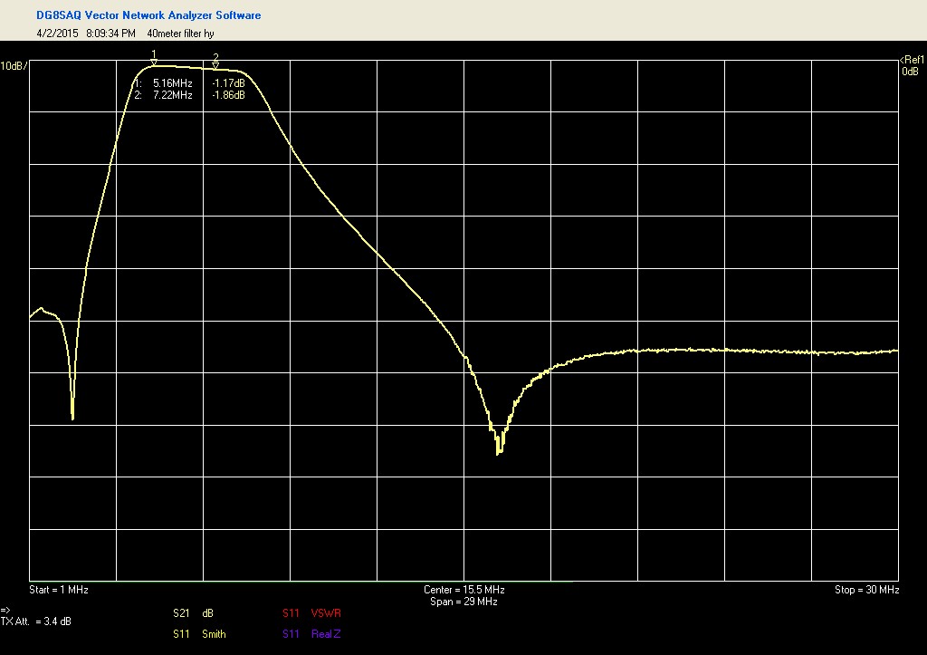
in3otd
Hello,
I've simulated the RS-HFIQ TX filters response, to have an
idea of the harmonics attenuation we could expect. Inductor Q was not
modeled as it should not have a significant effect in the stopband. The
40m/60m filter response looks a bit strange to me, there may be a mistake somewhere.

James Ahlstrom
On Saturday, July 15, 2017 at 1:02:11 PM UTC-4, in3otd wrote:
The 40m/60m filter response looks a bit strange to me, there may be a mistake somewhere.
James Ahlstrom
On Saturday, July 15, 2017 at 11:17:04 AM UTC-4, Steve Haynal wrote
suppression still be sufficient? Can you elaborate a bit more on your concerns?
James Ahlstrom
Graeme Jury
I don't have numbers for the harmonic output of the AFT05 amplifiers and probably we won't get any final plots until the 5 current beta boards are built and running. I would guess similarly to you that -20 dB at 2nd harmonic would be OK due to the push pull amplifiers already giving some suppression so the 3rd and 5th harmonics will be the issue. The most difficult filters to design for will be the 60/40M and 30/20M ones which both will just sneak in with > 22 dB or so suppression on the second harmonic if you are using an elliptic function filter of 5 poles and > 35 dB as you go up in frequency. It seems easy to place a zero on the second harmonic of the higher frequency of the dual band sets but not so easy with the third harmonic. All the other bands would be fine with Chebyshev or even half wave LP filters and they do have the advantage of increasing attenuation with frequency and matching inductor values. I know from your previous posts that you have already been down this trail and will already have arranged a suitable filter set so it is really a matter of knowing for certain what the harmonic output of the final version is. For my own filter I have finished up with 5 pole Cauer filters both HP and LP except for the 1.8 MHz HP filter which needed to be a 7 pole one to get a sharp enough stopband transition while keeping a low (better thn 30 dB) return loss in the passband. My intention is to have the filter as a universal filter but designed primarily for Hermes-Lite i.e. 100x100 board with either I2C or 4 digital control lines capable of levels up to 10 watts and providing ptt out and programmable delayed PA bias and facilities to pass back pwr and swr from an external amp via I2C. Over the top for most HL applications but as I said it is to be a general purpose one.
73, Graeme zl2apv
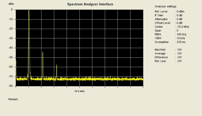
in3otd
there were some data on a standalone test PA in this thread and here enclosed are some measurements done on the current H-L v2b2; the PA supply was 9 V, with lower voltage the harmonics may be slightly worse (there were also some data on this somewhere).
There will surely be some variations between units and maybe w.r.t. the H-L v3, difficult to say how much.
73 de Claudio, IN3OTD /DK1CG