Shift register SPI interface to feather wing wiznet
1,037 views
Skip to first unread message

Mark T
Apr 23, 2019, 5:41:23 PM4/23/19
to RC2014-Z80
Looking at updating the micro SD card using shift registers to interface to the featherwing wiznet module. I thought I'd share the proposal here to see if this makes sense and if anyone can provide any input to avoid problems.
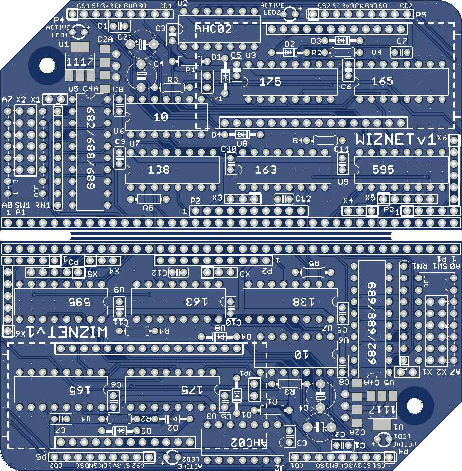
Below outline is proposed position of the featherwing module. According to the eagle files for the featherwing downloaded from the adafruit webpage this would put the front surface of the RJ45 socket flush to the edge of a 40 pin wide RC2014 module. If a case was designed based on 39 pin wide modules then a hole in the case might be required to accomodate the body of the RJ45 module.
I've included the 0.1 inch mounting holes for the featherwing module in this diagram, but I'm probably going to remove those as space is a bit tight. I think the two rows of header pins from the feather wing are probably going to be quite a solid mount of the featherwing module.
I'm intending to include the three pin header at the end of the featherwing for access to /IRQ and /RESET of the wiznet, according to the adafruit documents these are not necessary but possibly useful for future extension.
One option was to fit only one of the header pin strips to the featherwing module, together with the three pin header (which also includes /CS), as this would make it easier to move the ICs on the SPI board up and avoid so many changes to the layout, but I think this would make it a bit unstable.
I think female header socket strips on the RC2014 module and male header pins on the featherwing is probably the best combination. This also still allows the featherwing to be plugged into a breadboard for other experiments.
PMOD connector is removed, and I probably need to remove one of the micro sd card sockets to allow space to move the 74HCT175 which is needed to control /CS.
The 74HCT365 can also be removed, not needed to interface to the featherwing, and only really optional for sd card detect.
Keeping one of the sd card sockets might be useful to test the spi interface with something I already have working on the SD card module.
The featherwing wiznet module is 3.3v input output, but 5v tolerant, so I may be able to simplify the interface but probably safer to keep what already seems to work.
It might be possible to make a simpler module using CPLD, but using discrete TTL avoids any issue with programming parts. Another approach that might be neat would be to put the wiznet circuit directly on the RC2014 module instead of using the featherwing module.
Mark

Jay Cotton
Apr 23, 2019, 9:02:47 PM4/23/19
to RC2014-Z80
Well the smc parts are really hard to mount without special equipment. The featherwing at lease is assembled and allows a left footed builder (me)
put it together.
Dumping on of the SD cards is not really needed, just mount it on the back of the board. directly opposite the other one. very compact that way.
Also, it looks to me like you can squeeze the pin spacing on the featherwing a bit and really you only need 7 pins anyway. Maybe some mileage there.
It looks like you have the rj45 connector pointed in the correct direction, at least for my use it is.
The seven pins needed.... gnd, 3.3v, reset, cs, sclk, mosi, and miso. Well maybe IRQ .....
jc
Mark T
May 1, 2019, 2:23:13 PM5/1/19
to RC2014-Z80
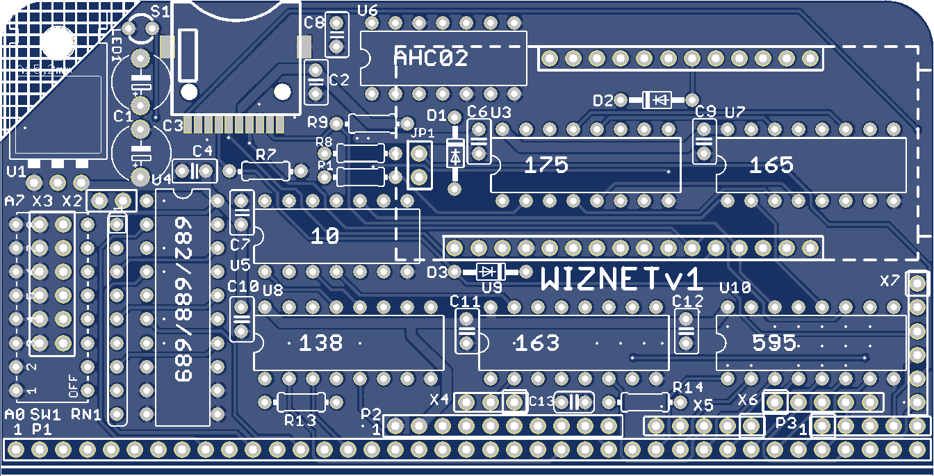
Board layout is a little closer to completion. I want to add more vias between top and bottom ground fill.
Still considering adding a header at the top edge for additional SPI experiments, indecision about pinouts, so many different breakout board formats for micro sd cards.
Added option for through hole TO220 regulator in place of SOT-323, moved the SOT-323 to solder side to avoid pads shorting to the TO220 metal tab. The TO220 hangs over the edge of the standard RC2014 outline and I'm not sure if thats OK or if the board outline should be changed. Perhaps with v-score to remove the corner if the SOT-323 is fitted, if thats permitted by the pcb manufacturers design rules.
Jay Cotton
May 1, 2019, 4:30:55 PM5/1/19
to RC2014-Z80
This looks really good. I can hardly wait to get my hands on it.
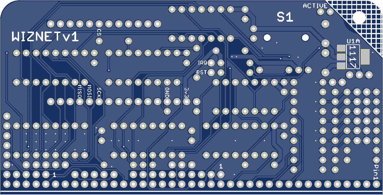
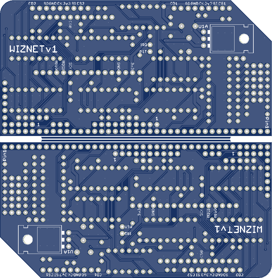
I am looking at the schematic, but I don't see how IRQ gets to the the INT line.
What am I missing.
jc
Mark T
May 1, 2019, 7:18:22 PM5/1/19
to RC2014-Z80
As it is now the IRQ can be linked to one of the user pins so it can be connected to a CTC module. I haven't checked yet if the IRQ output of the featherwing is open collector to allow connection to the /INT line of the Z80 bus without worrying about other connections to /INT.
Mark
Mark T
May 1, 2019, 9:21:19 PM5/1/19
to RC2014-Z80
Datasheet for 5500 doesn't say IRQ is open drain or open circuit so I'd be wary of connecting directly to /INT. Output low max is 0.4v although this is at 8mA, I'm not sure it would meet Input low requirements of Z80 if a schottky diode is used. I'll try and add option so it can be tested to see if it works. It might be better to add an open collector buffer if I can find space.
Mark
Jay Cotton
May 2, 2019, 12:00:03 AM5/2/19
to RC2014-Z80
I just was looking at a BS170 transistor. I think it can fix the loading problem and, in the off state its kind of an open collector circuit.
If that will not work, then skip the interrupt. They are hard to do without a ctc board anyway. I did like your CTC as an interrupt source.
I have used that my self a few time.
BTW: I am thinking of Alan Cox with the interrupt. Using that on fuzix would make concurrent i/o possible, a very unix like thing to do.
Very eager for the new board.
jc
Mark T
May 2, 2019, 2:11:02 AM5/2/19
to RC2014-Z80
I should probably take another look at Steve Cousin’s CTC module, and maybe the CTC/SIO to see if the link options i’ve used are compatible.
My own CTC module is intended for different configuration of user pin connections in the bus, although it should work on a standard rc2014 bus too.
Steve’s board is probably already used by quite a few people that might want to play with wiznet.
Mark
My own CTC module is intended for different configuration of user pin connections in the bus, although it should work on a standard rc2014 bus too.
Steve’s board is probably already used by quite a few people that might want to play with wiznet.
Mark

Alan Cox
May 2, 2019, 7:29:52 AM5/2/19
to rc201...@googlegroups.com
On Thu, 2 May 2019 at 05:00, Jay Cotton <lbmg...@gmail.com> wrote:
>
> I just was looking at a BS170 transistor. I think it can fix the loading problem and, in the off state its kind of an open collector circuit.
>
> If that will not work, then skip the interrupt. They are hard to do without a ctc board anyway. I did like your CTC as an interrupt source.
> I have used that my self a few time.
>
> BTW: I am thinking of Alan Cox with the interrupt. Using that on fuzix would make concurrent i/o possible, a very unix like thing to do.
I am not sure the interrupt is actually that useful. It saves a poll
>
> I just was looking at a BS170 transistor. I think it can fix the loading problem and, in the off state its kind of an open collector circuit.
>
> If that will not work, then skip the interrupt. They are hard to do without a ctc board anyway. I did like your CTC as an interrupt source.
> I have used that my self a few time.
>
> BTW: I am thinking of Alan Cox with the interrupt. Using that on fuzix would make concurrent i/o possible, a very unix like thing to do.
of the device each timer tick, but it costs you all the interrupt
overhead every time it decides to poke you. Wired through a CTC or PIO
I suspect it would actually be more efficient in the Fuzix case to
just read the I/O register each timer tick to reduce the number of
slower SPI transactions than actually use it for an interrupt.
Interactive use might feel slightly better with an IRQ but probably not a lot.
Alan
Mark T
May 15, 2019, 11:23:17 AM5/15/19
to RC2014-Z80
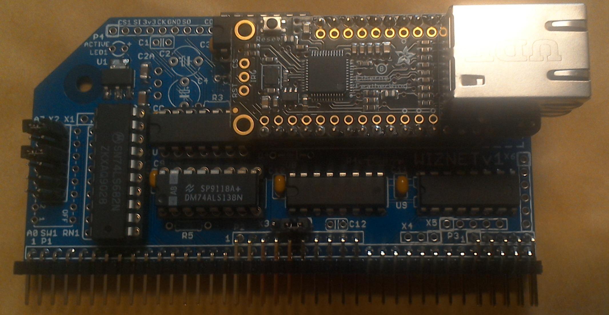
Just sent this to JLCPCB for Manufacture.
Removed the micro SD card connector and instead added headers for micro SD card break out boards.
I kept the option to use a TO220 regulator, but this is mounted to the solder side of the board to avoid shorting to pads for the SMD part. Also by mounting on the solder side the pinout is better suited to routing. It would still be possible to mount the TO220 from the top side of the board, either face down to the pcb or mounted vertically.
The height of the module will be quite High, I think about 27mm, due to the header pins to the WIZNET module plus the height of the RJ45 connector. I'll also need to be carefull not to allow shorting to an adjacent module, but its probably best to mount this in the first slot of a backplane.
It might be possible to reduce the height a little by not using IC sockets and using round pin socket strip and pins to mount the featherwing. Another alternate may be to mount the featherwing on the solderside of the module, but that would need header pins with a board to board height of 15mm.
Mark
Jay Cotton
May 15, 2019, 12:12:42 PM5/15/19
to RC2014-Z80
Looks great. I like your TO220 solution.
Slight concern, reset line connected to Q4 74138. I used that as the " nothing selected " selection.
We may need to work around that.
jc
Mark T
May 15, 2019, 12:28:45 PM5/15/19
to RC2014-Z80
Hi Jay,
Did you mean /RST connected to /Q4 of U3 the 74HCT175 ?
We could just not fit D1, that was just an option in case there was an advantage to being able to reset the wiznet without resetting the z80.
I just noticed that I left D2 as DNP, of course it needs to be fitted to control CS of the wiznet.
Mark
Jay Cotton
May 15, 2019, 5:14:04 PM5/15/19
to RC2014-Z80
Yes. And I was thinking the same thing, leave out the diode.
Mark T
May 24, 2019, 5:57:20 PM5/24/19
to RC2014-Z80
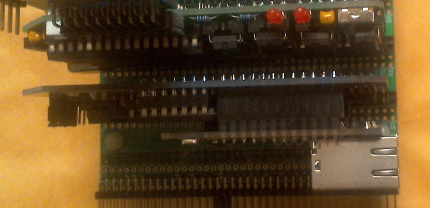
Received the boards yesterday, built one today and tested using the software Jay provided a few weeks ago.
Worked first time running ipconfig and ping.
I decided to try the blue color from JLCPCB just for a change and because its no extra charge now. It seems to be a slightly darker blue than other photos I've seen of RC2014 modules but that might just be the lighting of the photos.
As expected the depth of the module with the Wiznet fitted into female header pins is a bit high, approx 1.1 inch, so takes up two slots on the backplane unless fitted at the first slot.
Mark
Jay Cotton
May 24, 2019, 8:57:31 PM5/24/19
to RC2014-Z80
Probably to late now, but an optimization for the board would be to mount the feather wing upside down on the back of the board with the rj45 hanging
out over the end of the board. That would tighten up the spacing to allow the board to fit anywhere on the bus. It is however now done and working.
SO, I guess is need a few.
Mark T
May 24, 2019, 11:52:12 PM5/24/19
to RC2014-Z80
I think i prefer to keep the featherwing module within the outline of the module, as this suits my plan to build a case around a modular backplane. It might have been better to move the rj45 connector 1.6mm further outwards.
Another alternate that might suit an enclosure would be to mount the featherwing module on the rear panel, with an adapter and ribbon cable to the spi module.
Mark
Jay Cotton
May 25, 2019, 12:13:07 AM5/25/19
to RC2014-Z80
ribbon cable is a good solution.
jc
Jay Cotton
May 25, 2019, 11:03:23 PM5/25/19
to RC2014-Z80
I have posted the code on github at https://github.com/jayacotton
Jay Cotton
May 28, 2019, 10:27:00 PM5/28/19
to RC2014-Z80
Got my boards today, and yep, another running rc2014 board.
um, somewhat embarrassed to say that I am our of room on my backplane..... think I need to get a few more...
hmmmmm networked z80 cluster....
Jay Cotton
May 28, 2019, 10:30:30 PM5/28/19
to RC2014-Z80
To bad we can't edit replys.
I was about to say, I mounted my featherwing board on the back side of the SPI board. I used Arduino extender sockets
and boost the board off a bit.. I'll get a pix latter. With this setup I can plug the board into the last socket on my bus.
Mark T
May 29, 2019, 12:04:08 AM5/29/19
to RC2014-Z80
Github with gerber files for the board:-
I've included a link to Jay's github for software from the readme file.
Mark
Mark T
May 29, 2019, 9:25:32 PM5/29/19
to RC2014-Z80
It looks like you didn’t fit the 10 uF caps for the regulator.
Are you sure you meant to connect Qd to U1A? This would be Tx2 or Rx2 on a standard Rc2014 backplane.
You left R1 not fitted, which maybe ok with the wiznet, not sure if it already has a pull up on the featherwing.
Mark
Are you sure you meant to connect Qd to U1A? This would be Tx2 or Rx2 on a standard Rc2014 backplane.
You left R1 not fitted, which maybe ok with the wiznet, not sure if it already has a pull up on the featherwing.
Mark
Jay Cotton
May 29, 2019, 10:25:29 PM5/29/19
to RC2014-Z80
So much nicer to have the correct schematic. I guess I printed the wrong version or something.
Parts added or subtracted as needed.

Douglas Miller
Oct 25, 2019, 9:09:31 AM10/25/19
to RC2014-Z80
Looks like you already got this working, but FYI there is a similar WIZNET interface to the Heathkit H8 that I worked on, and it works with Z80 block I/O instructions. We've been running CP/NET on it. The wiznet module is WIZ850io - also 5500 based. It has been shown to work at 10Mhz. It also adds an (SPI) NVRAM chip to hold network configuration. I've got a version of CP/NET for CP/M-Plus (v3) as well. If anyone is interested.
Mark T
Apr 28, 2020, 5:15:28 PM4/28/20
to RC2014-Z80
Just adding a note here as it's not possible to edit earlier posts.
If anyone does download the gerber data from github please also use the schematic from github and not the one posted in this thread which has some issues with D2 marked as DNP, do not fit, but is required to provide CS to the wiznet module.
Mark

asmagi...@gmail.com
Sep 27, 2024, 11:06:40 PM9/27/24
to RC2014-Z80
Late to the party, but this caught my interest as I have most of the necessary parts already... if I want to add the FRAM as suggested at https://github.com/durgadas311/cpnet-z80/blob/master/md/MT011.md, I need to populate D4, even though the github schematic shows it as DNP, correct?
A-Ron
Mark T
Sep 28, 2024, 12:26:22 AM9/28/24
to RC2014-Z80
If you are connecting the fram to P4 you should fit D4, probably best to use a schottky diode, bat85 or similar.
I’ve not tried adding an fram, so not sure if the fram has an internal pull up on cs, or if that should also be added to the fram wiring.
asmagi...@gmail.com
Oct 13, 2024, 3:04:52 AM10/13/24
to RC2014-Z80
The schematic for the fram board doesn't show a pull-up on CS, so I'm going to assume I need one. Unless I'm missing something, I don't see a spot for it on board, so I'm guessing I'll need to add it to the daughter-board I'm making for the fram module since the pin order differs.
Mark T
Oct 13, 2024, 11:33:52 AM10/13/24
to RC2014-Z80
The two extra spi connectors were intended for micro sd cards, which have internal pull up on cs which can be used to detect if a micro sd card is connected.
Does the fram have an internal pull up?
Reply all
Reply to author
Forward
0 new messages