Compact Flash uSD Adapter in IDE Hard Drive Module
2,869 views
Skip to first unread message

Phillip Stevens
Jul 26, 2022, 7:27:24 AM7/26/22
to RC2014-Z80
On a different thread we were discussing the micro SD Compact Flash Adapter, and whether it works with Spencer's IDE Hard Drive Module (with the 82C55 Device).


Well, in short it does. The only limitation that I've found is that the maximum SD card suitable for use is 128GB. Beyond this it seems to crap out. That's mentioned (in a very roundabout way) on the packaging. FAT32 runs out at 128GB too, so it is really not a limitation.
So, rather than just posting some packaging, I've done a bit of testing versus a real modern CF card (Verbatim), and an Acer DOM. Cutting to the chase, the DOM is only very slightly faster to copy 1MB files in CP/M, about 3 seconds in 47 seconds.
This may be affected by the SD card chosen. I did my testing with a reasonably fast Ultra SanDisk SD card, but this may not be too important, given the rate we're working at.
However, in the PC world the SD Card performance is very variable. I tested a write speed of 4.2MB/s for a generic SanDisk, 10.8MB/s for an Ultra SanDisk, and 21.3MB/s for an Ultra A1 Sandisk. The Verbatim 1GB CF card achieves 17.2MB/s write speed, for reference.
So using PIP the it takes about 47 seconds to copy a 1MB file with either the uSD card in the CF Adapter, or a real CF Card. It takes about 44 seconds to do the same to an IDE DOM, which is insignificantly faster in the scheme of things.
It is usually much easier to handle uSD and SD cards than DOMs or CF cards in modern laptops and computers. So these Adapters look like the way forward.
The testing was done on CP/M-IDE. I'll do a follow-up post with RomWBW shortly.
Cheers, Phillip

Nick Brok
Jul 26, 2022, 7:56:04 AM7/26/22
to RC2014-Z80
I use sd to cf adapters for a long time, they work very nice.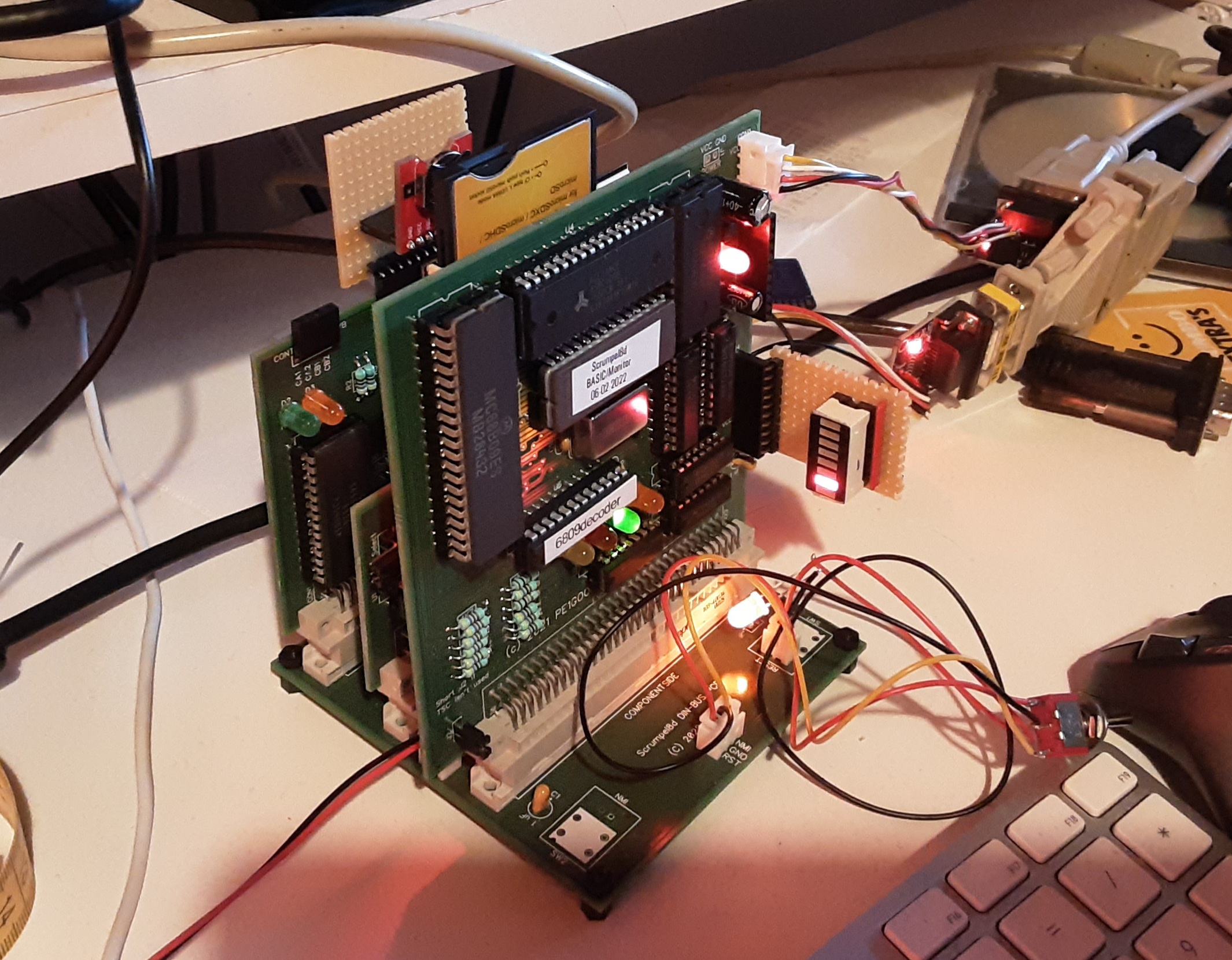
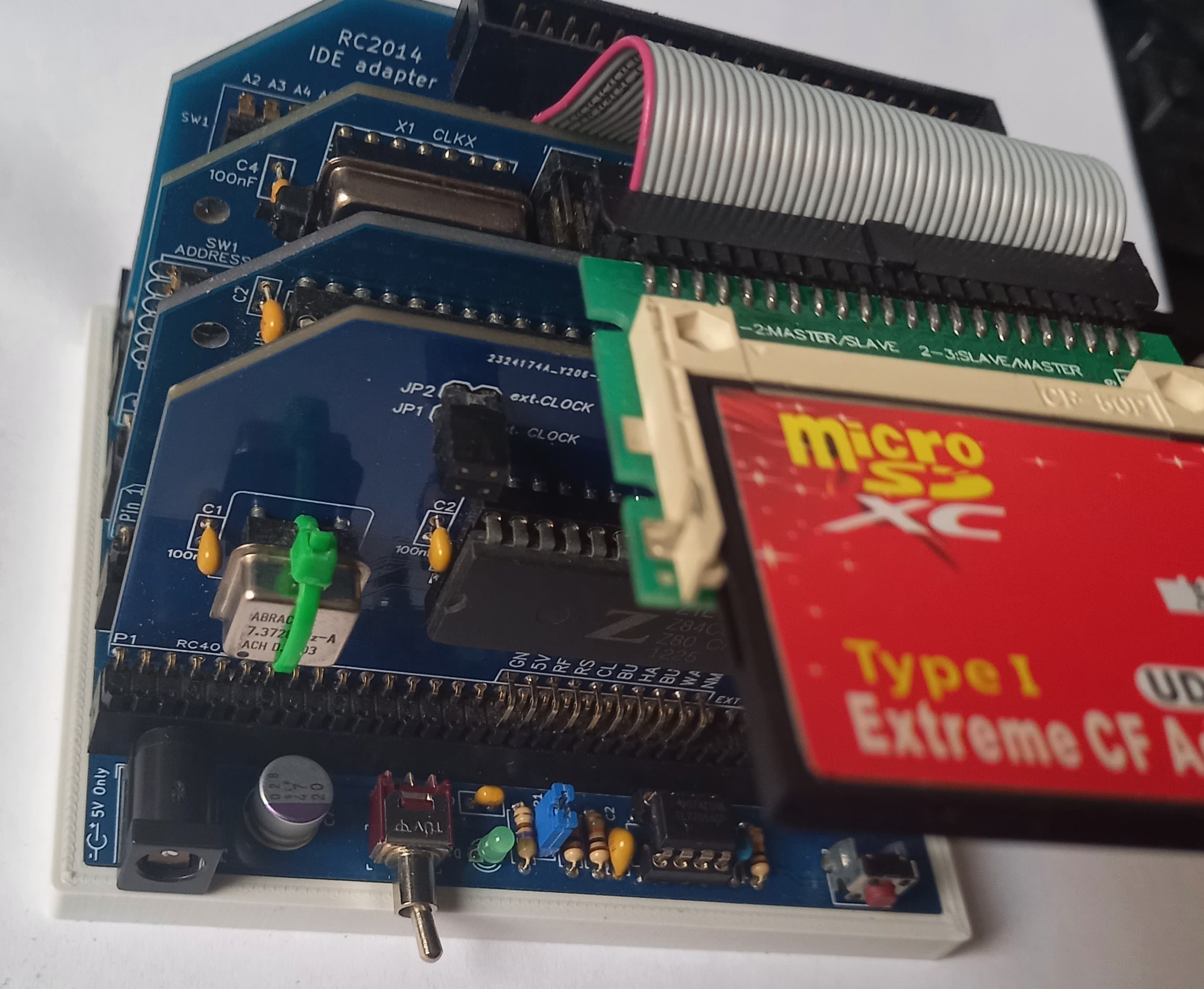
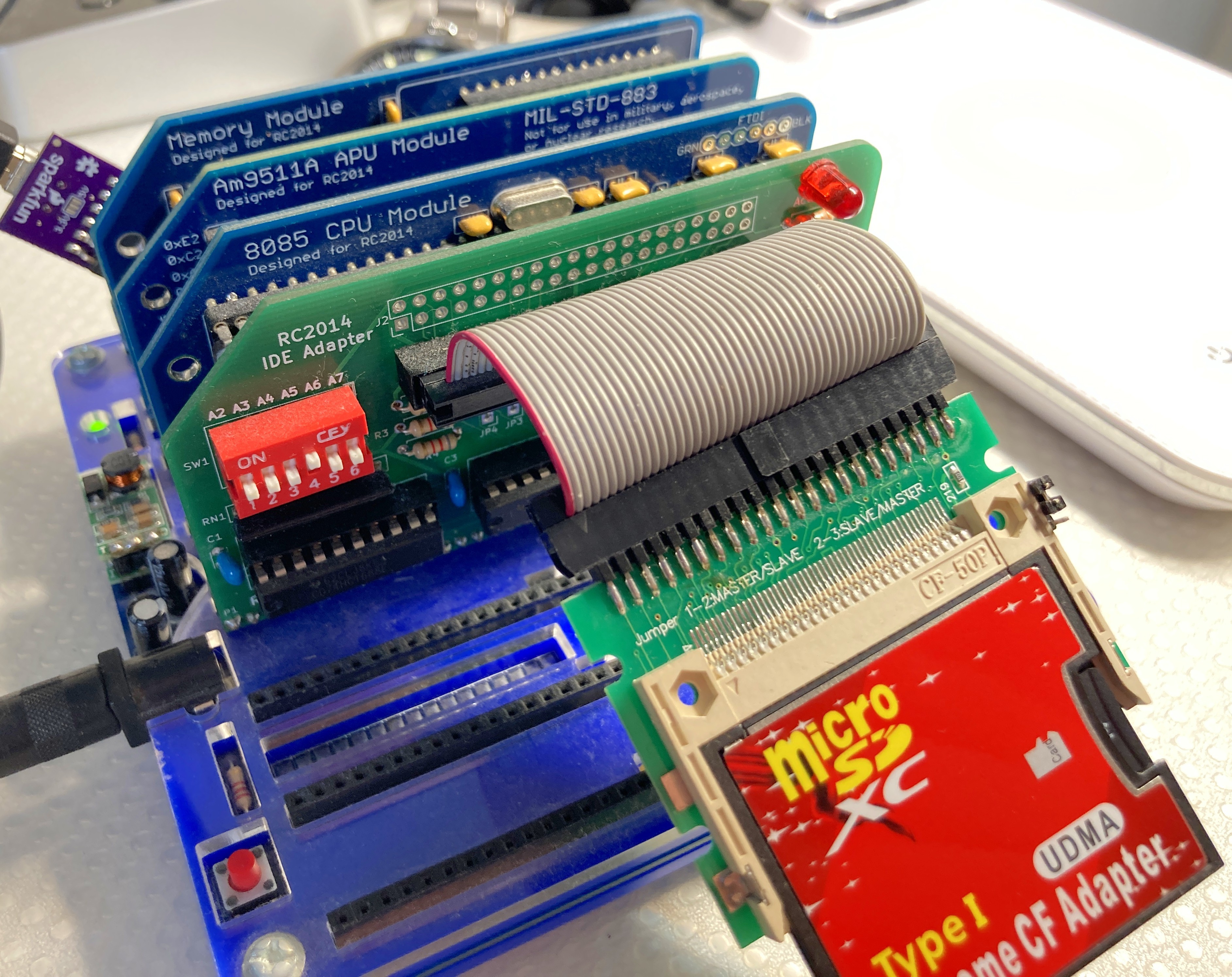
Look at the board behind the CPU. I use a 2GB sd card in the cf adapter.
Op dinsdag 26 juli 2022 om 13:27:24 UTC+2 schreef Phillip Stevens:
Phillip Stevens
Jul 26, 2022, 8:05:29 AM7/26/22
to RC2014-Z80
Nick wrote:
I use sd to cf adapters for a long time, they work very nice. Look at the board behind the CPU. I use a 2GB sd card in the cf adapter.
I guess the other interesting thing is that it looks like there's an 8051 CPU driving the SD->CF Adapter.
I wonder what it looks like inside? Whether it has an exposed UART for example?
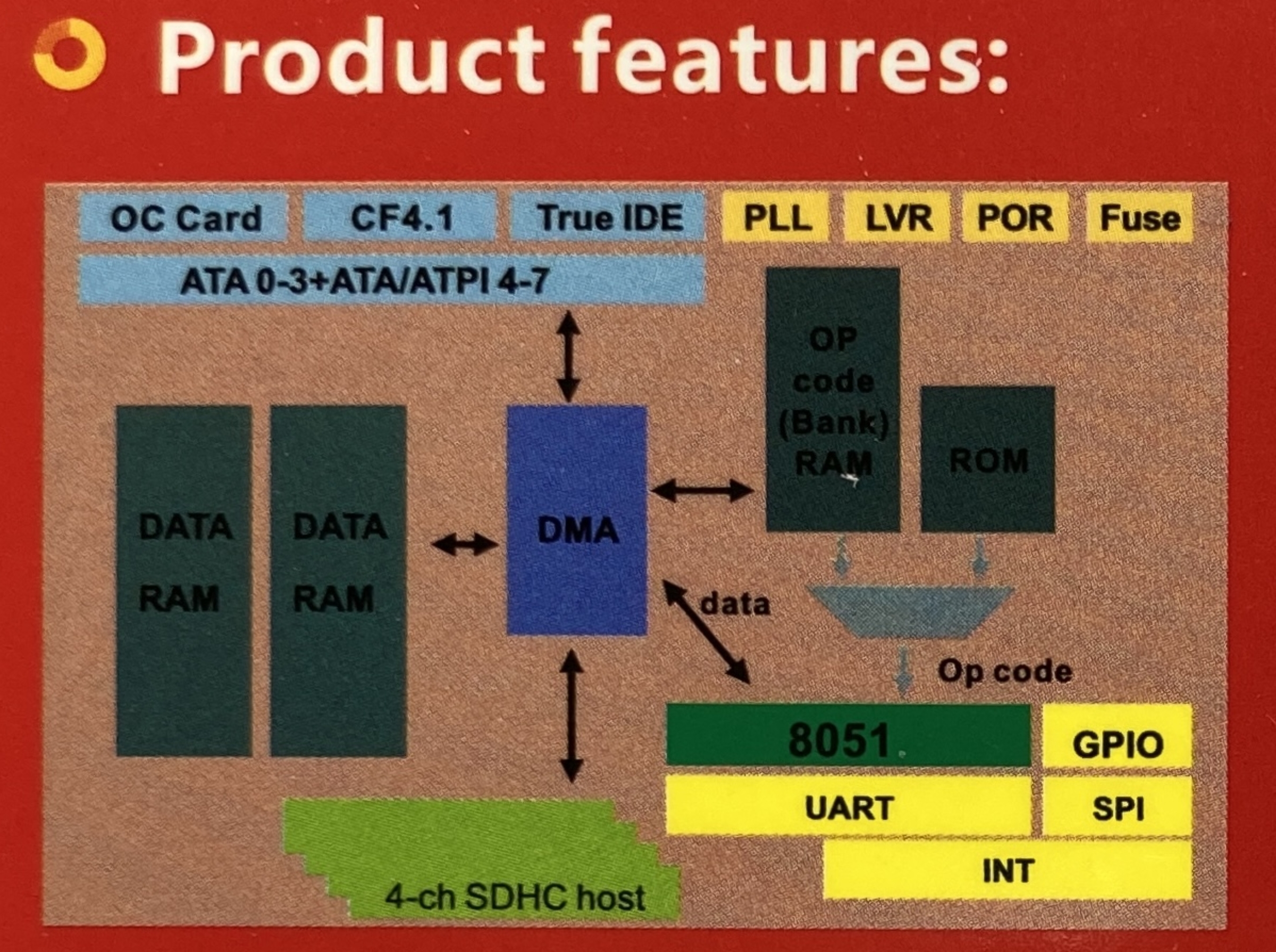
Not sure I want to break mine to find out though.

Tadeusz Pycio
Jul 26, 2022, 9:25:06 AM7/26/22
to RC2014-Z80
Unfortunately, in my case, a similar looking SD to CF adapter blocks with each SD card (I tested from 128MB to 16GB) the start of RomWBW ~30 sec to finally start with a message of no media. I use the official IDE module from the PLCC PPI.
Using the SD to IDE adapter on the same SD cards starts the system and accesses their contents. It is possible that my adapter is different, despite the similarity. It is comforting to know that it works on a buffered CF module.
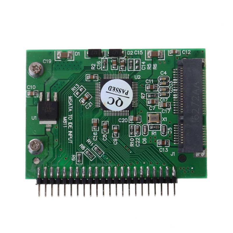
Good thing we started this thread as I have discovered another cheap source of storage for our RC2014s. It's an MSATA to IDE adapter which you can buy on a well-known Chinese online shop for $4 and you can get used 2GB MSATA modules at a similar price. I have ordered one set and when it arrives I will share my test results.
Phillip Stevens
Jul 26, 2022, 9:54:09 AM7/26/22
to RC2014-Z80
Tadeusz wrote:
Unfortunately, in my case, a similar looking SD to CF adapter blocks with each SD card (I tested from 128MB to 16GB) the start of RomWBW ~30 sec to finally start with a message of no media. I use the official IDE module from the PLCC PPI.Using the SD to IDE adapter on the same SD cards starts the system and accesses their contents. It is possible that my adapter is different, despite the similarity. It is comforting to know that it works on a buffered CF module.

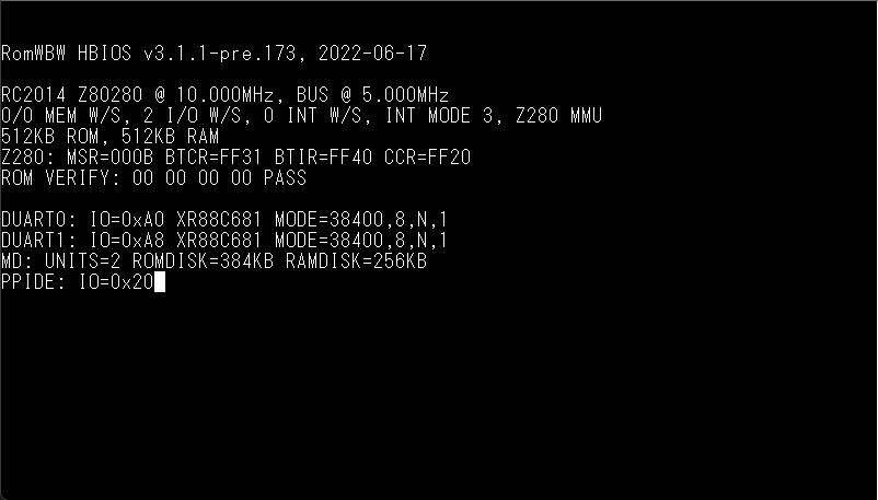
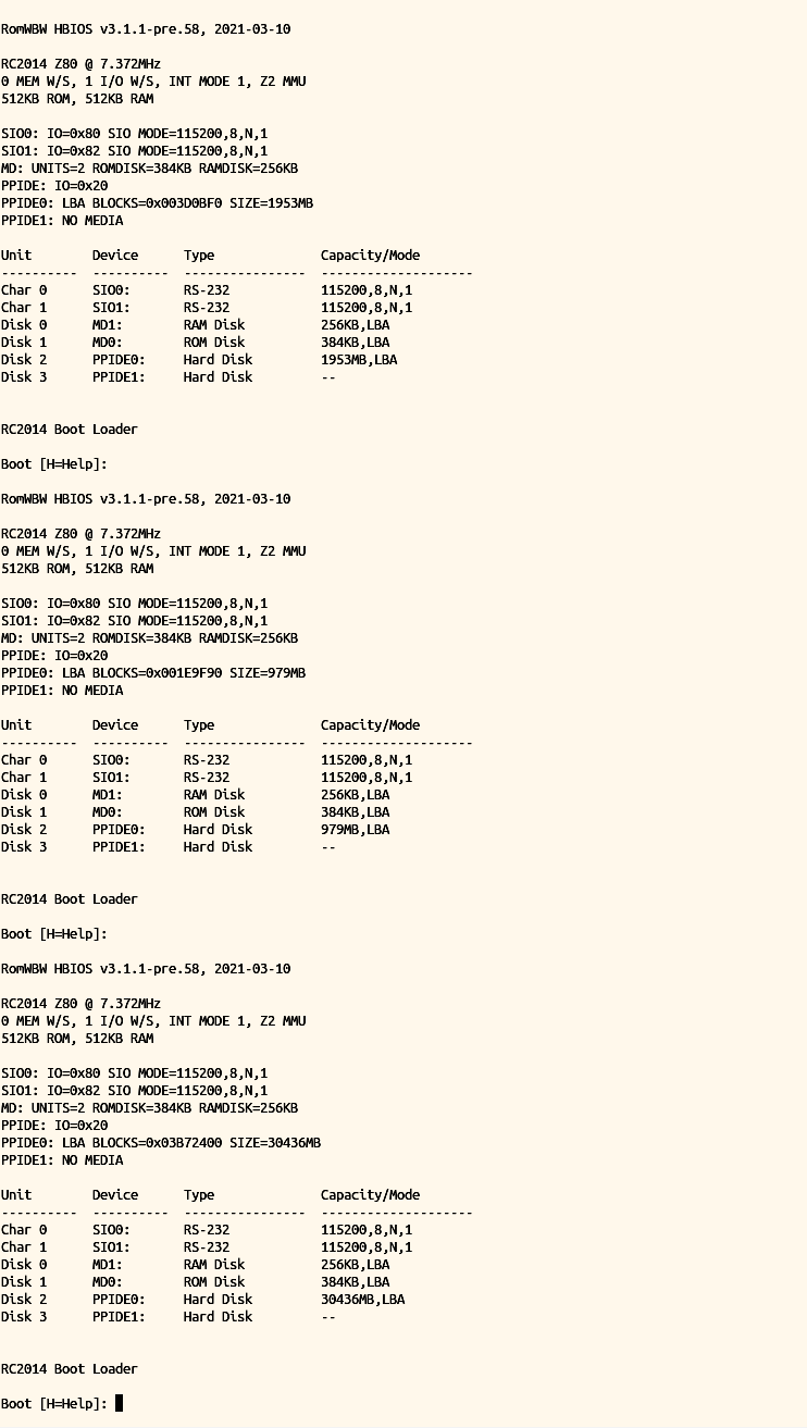
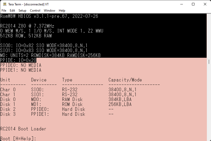
I've just plugged in a "standard" RC2014 (z80 + SIO2 + 512k/512k + IDE), with an older v3.1.1-pre.58 image.
I don't have a slice file system installed (my drives are all FAT32), but it doesn't block at the ID phase, and it recognises the drive size, etc.
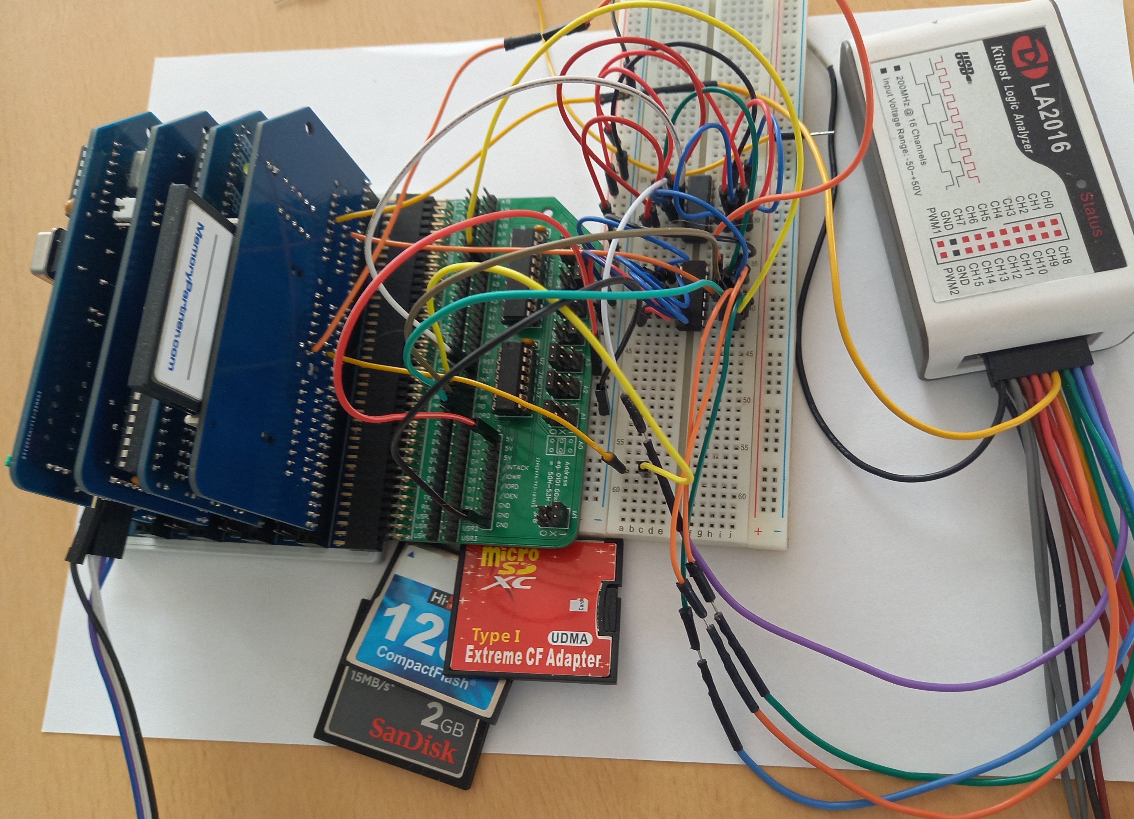
Below a screen shot with 1st. 2GB DOM, 2nd. 1GB CF Card, and 3rd. 32GB uSD card in adapter, RESET between each boot.
So, either there's a regression in the RomWBW driver, or there's something peculiar about the Z280 that isn't playing nice.
Not sure where the issue will be coming from, I'm sorry.
Cheers, Phillip

Bill Shen
Jul 26, 2022, 10:12:42 AM7/26/22
to RC2014-Z80
I have tested my SD to CF adapter on 68332 with 16-bit CF data bus, it worked. I also tested it with Z80 with 8-bit CF interface, it also worked. I have not tested it with Z280 in ROMWBW setup, so I’ll try that later today.
Bill
Tadeusz Pycio
Jul 26, 2022, 1:30:33 PM7/26/22
to RC2014-Z80
I built a similar set up, unfortunately I didn't have the same version of RomWBW so I compiled the closest one to the one shown - same effect, stopping after PPIDE: IO=0x20 (shorter this time) and then continuing to boot without detected media. Must be something different about my SD to CF adapter.

Wayne Warthen
Jul 26, 2022, 2:52:21 PM7/26/22
to RC2014-Z80
Interesting discussion... I have never tried one of these SD-CF adapters. I just ordered a couple of them and should get them on Thursday. This should allow me to replicate most of the scenarios being described.
I guess there could be an issue with RomWBW, but it seems unlikely since there do not seem to be any issues with CF Cards in general (other than hardware anomalies on the unbuffered boards).
Thanks,
Wayne
Tadeusz Pycio
Jul 26, 2022, 4:05:42 PM7/26/22
to RC2014-Z80
I don't think it's a RomWBW problem, probably these adapters are different despite identical markings. Mine works with the PC and with the buffered CF module, but in the IDE module it won't work. It's a good thing it finally worked, as it had been lying in a drawer uselessly for a year. I've been wanting to build an IDE module, a GIDE replica on a 74HCT646 customised for RC2014 for a while, but I keep putting it off. Maybe it will behave differently there.
Bill Shen
Jul 26, 2022, 5:30:44 PM7/26/22
to RC2014-Z80
My SD-to-CF adapter works with unbuffered CF interface (i.e., no 74245 between CF data lines and Z80's data line). However, many of my designs bootstrap from the first sector of CF disk (Master Boot Block). I'm not able to bootstrap from SD-to-CF adapter for those designs, but I think that's a different issue.
I do have a Z280 design with the traditional 512K RAM, ROM and unbuffered CF interface. It works with SD-to-CF adapter.
Bill
I do have a Z280 design with the traditional 512K RAM, ROM and unbuffered CF interface. It works with SD-to-CF adapter.
Bill
Tadeusz Pycio
Jul 26, 2022, 6:50:17 PM7/26/22
to RC2014-Z80
I checked this adapter with Steve's test program, the top result on Spencer and Karl's #10f modules gives the same result, below already correctly recognised SD card after using the buffered CF module.
Perhaps this correctly read information is different from the adapters you have? I am curious about the results.
Perhaps this correctly read information is different from the adapters you have? I am curious about the results.
Bill Shen
Jul 26, 2022, 11:29:57 PM7/26/22
to RC2014-Z80
SCMonitor's CF information Apps does not run on my Z280 hardware, so I did a quick mod of my monitor to send the "Identity" command ($EC) and display the returned raw data. The raw data are byte-swapped, so the adapter information is:
Rev 1.5 FC-1307 SD to CF Adapter V1.5
I guess it is a newer model (rev1.5) than yours (rev 1.3).
Bill
Rev 1.5 FC-1307 SD to CF Adapter V1.5
I guess it is a newer model (rev1.5) than yours (rev 1.3).
Bill
Phillip Stevens
Jul 27, 2022, 8:01:14 AM7/27/22
to RC2014-Z80
Bill wrote:
SCMonitor's CF information Apps does not run on my Z280 hardware, so I did a quick mod of my monitor to send the "Identity" command ($EC) and display the returned raw data. The raw data are byte-swapped, so the adapter information is:
Rev 1.5 FC-1307 SD to CF Adapter V1.5
I guess it is a newer model (rev1.5) than yours (rev 1.3).
Bill
Tadeusz wrote:I checked this adapter with Steve's test program, the top result on Spencer and Karl's #10f modules gives the same result, below already correctly recognised SD card after using the buffered CF module.
Perhaps this correctly read information is different from the adapters you have? I am curious about the results.
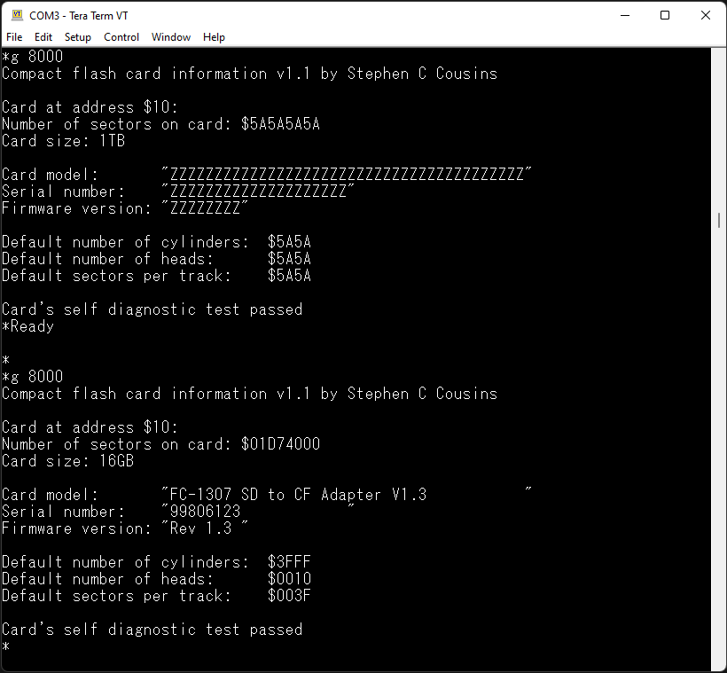
I've written a little program which will print out the low level disk attributes, and found that my brand new SD->CF adapter is firmware revision 1.3.
So this is getting quite curious...
I wonder how many different firmware versions are in the wild?
B>diskchk
**** Initialise disk ****
disk_initalize(0) - ok
**** Get firmware revision ****
disk_ioctl(0, ATA_GET_REV, 0x17EB) - ok
Firmware revision is Rev 1.3
**** Get model name ****
disk_ioctl(0, ATA_GET_MODEL, 0x17EB) - ok
Model name is FC-1307 SD to CF Adapter V1.3
**** Get serial number ****
disk_ioctl(0, ATA_GET_SN, 0x17EB) - ok
Serial number is 042FCB67
**** Get drive size ****
disk_ioctl(0, GET_SECTOR_COUNT, 0xE1E1) - ok
Number of sectors on the drive is 62333952
**** Get sector size ****
disk_ioctl(0, GET_SECTOR_SIZE, 0xE1E7) - ok
Size of sector is 512 bytes.
**** Get block size ****
disk_ioctl(0, GET_BLOCK_SIZE, 0xE1E5) - ok
Size of the erase block is 1 sector(s).
Tadeusz Pycio
Jul 27, 2022, 11:33:24 AM7/27/22
to RC2014-Z80
We are back to square one. We have the same adapters, with the same firmware, and different results. Today I'm going to try to bypass the buffer, as I have a different way of controlling it, relative to the available CF modules (thank you Steve and Bill - interestingly I've reached the same point as someone has before - https://github.com/PickledDog/rc-cfcard), and further this doesn't solve the problem of not working in the IDE module. I will share the results without the 245 buffer later.
Tadeusz Pycio
Jul 27, 2022, 1:32:20 PM7/27/22
to RC2014-Z80
Removing the buffer 245 and bridging, no change, the adapter still works. The problem is in the control, a question whose timing we do not provide....

Spencer Owen
Jul 27, 2022, 1:46:56 PM7/27/22
to rc201...@googlegroups.com
FWIW, I tried a couple of the full size SD adapters with a selection of cards and didn't get any positive results. They were just tested with the standard image I use on CF cards, and the test was just a working/non-working test, but after a few goes I gave up on them.
Spencer
--
You received this message because you are subscribed to the Google Groups "RC2014-Z80" group.
To unsubscribe from this group and stop receiving emails from it, send an email to rc2014-z80+...@googlegroups.com.
To view this discussion on the web, visit https://groups.google.com/d/msgid/rc2014-z80/7eae9ffd-5419-4d48-8c10-06cfcde24d24n%40googlegroups.com.
Bill Shen
Jul 27, 2022, 3:20:45 PM7/27/22
to RC2014-Z80
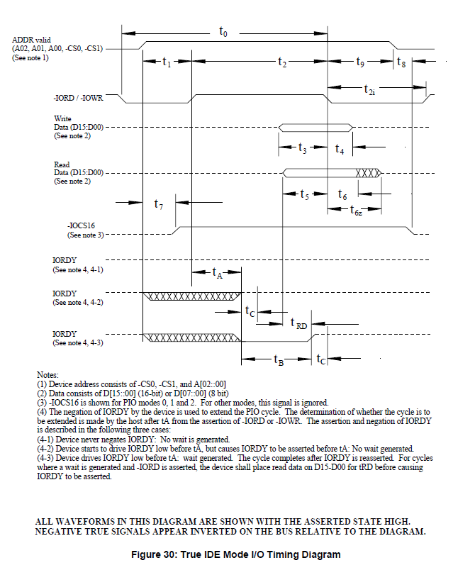
Apparently the SD-to-CF adapter requires positive setup time (t1) from CF chip select asserted to CF_read or CF_write asserted. Some brand of CF card works with no setup time or even negative setup time, but not this SD-to-CF adapter. Positive setup time can be achieve by generating CF chipselect from M1 and addresses (no IORQ involved) and generating CF_write and CF_read qualified with IORQ.
Bill
Bill
Tadeusz Pycio
Jul 27, 2022, 3:31:02 PM7/27/22
to RC2014-Z80
Bill, my module works according to the method you describe, it may be worth trying to take a different path, delay the appearance of /RD and extend the low level /IORQ which controls the full decoder /CS of the CF card.
Phillip Stevens
Jul 27, 2022, 5:41:15 PM7/27/22
to rc201...@googlegroups.com
Spencer wrote:
FWIW, I tried a couple of the full size SD adapters with a selection of cards and didn't get any positive results. They were just tested with the standard image I use on CF cards, and the test was just a working/non-working test, but after a few goes I gave up on them.Spencer
Spencer did you try them with your IDE Hard Drive Module, as per the OP subject?
I’ve a feeling that they are made to work in native 16-bit IDE Mode, as per packaging, “True IDE” and “ATA 0-3”.
Anyway if you’ve still got them have a look with your IDE Module and let us know what you think.
Cheers Phillip
Sent from a Mobile Device.
Replies may appear terse.
Bill Shen
Jul 27, 2022, 9:45:45 PM7/27/22
to RC2014-Z80
Tadeusz,
When CPLD is available, my CF interface design looks like this.

When design with TTL logic, my CF interface looks like this.

Both designs are very robust with Zx80 timing. However, the CPLD CF design doesn't work 100% when implemented in 680x0 timing where I also need to implement the hold time (t9), and even that is still not 100%. There is a forum member here who seems to be able to reach 100% success with 680x0 CF interface, I hope he'll chime in.
Bill
PS, the PDF-to-JPEG conversion is not very good. Here are the original PDF files
When CPLD is available, my CF interface design looks like this.
When design with TTL logic, my CF interface looks like this.
Both designs are very robust with Zx80 timing. However, the CPLD CF design doesn't work 100% when implemented in 680x0 timing where I also need to implement the hold time (t9), and even that is still not 100%. There is a forum member here who seems to be able to reach 100% success with 680x0 CF interface, I hope he'll chime in.
Bill
PS, the PDF-to-JPEG conversion is not very good. Here are the original PDF files
Phillip Stevens
Jul 28, 2022, 2:24:18 AM7/28/22
to RC2014-Z80
Wayne wrote:
Interesting discussion... I have never tried one of these SD-CF adapters. I just ordered a couple of them and should get them on Thursday. This should allow me to replicate most of the scenarios being described.I guess there could be an issue with RomWBW, but it seems unlikely since there do not seem to be any issues with CF Cards in general (other than hardware anomalies on the unbuffered boards).
Another data point:
To check whether there is a regression in RomWBW HBIOS, I've built the latest dev branch for the standard RC2014 configuration (SIO2 + 512k/512k + Spencer IDE).
I can confirm RomWBW pre.183 is working with the SD->CF Adapter with the firmware v1.3, with Spencer's IDE Module.
Also, I can confirm that HBIOS is much faster than CP/M in disk access.
The HBIOS Monitor using the FATFS file system can copy 1MB in 18 seconds, vs 47 seconds on CP/M file system for the same file copy.
So on CP/M the uSD card in the CF adapter can do about 50kBytes/sec using PIP.
And PIP is super optimised. It is very difficult to do faster within CP/M.
With HBIOS + FATFS the same storage medium can do about 116kBytes/sec (average of read and write).
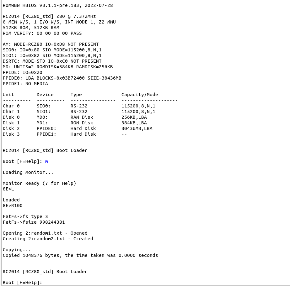
I've attached the C program (uploaded into the RomWBW Monitor) which reads a file called random1.txt and writes random2.txt, then deletes it.
Because the RC2014 doesn't have a system tick, timing has to be done by hand.
zcc +rc2014 -subtype=hbios -clib=sdcc_iy -SO3 -m --list --max-allocs-per-node100000 -llib/hbios/time -llib/hbios/diskio_hbios -llib/hbios/ff fileCopyTest.c -o fileCopyTest -create-app
Wayne Warthen
Jul 28, 2022, 6:54:12 PM7/28/22
to RC2014-Z80
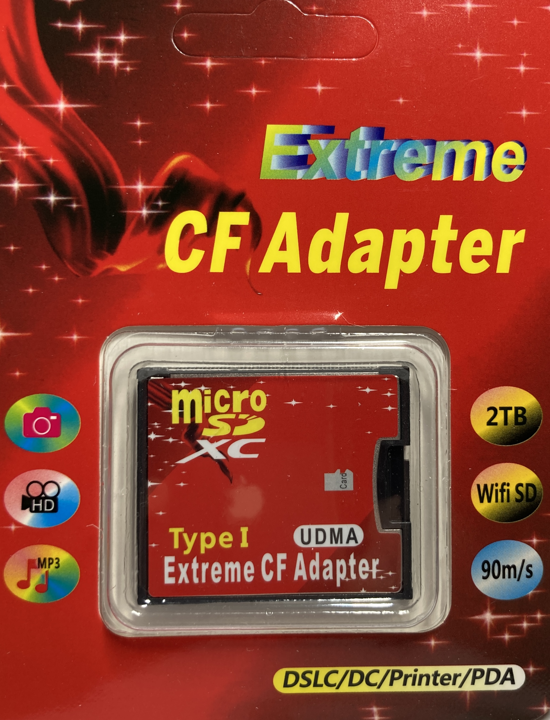
I have received the SD-CF Adapters that I ordered. In the attached picture, the first one (Red) is like everyone else seems to have. The second one (White) also calls itself an Extreme CF Adapter, but says something about "3rd generation" -- no idea what that refers to.
Red identifies itself as:
SN: "50277237 "
Revision: "Rev 1.3 "
Model: "FC-1307 SD to CF Adapter V1.3 "
Revision: "Rev 1.3 "
Model: "FC-1307 SD to CF Adapter V1.3 "
White identifies itself as:
SN: "2C1003531 "
Revision: "00000011"
Model: "INIC-2051 CompactFlash Card "
Revision: "00000011"
Model: "INIC-2051 CompactFlash Card "
In my testing, I am finding that both cards struggle with an unbuffered IDE interface. Neither work in my RC2014 CF Module. However, Red does work in Bills ZZ80MB where White does not. I conclude that they are generally not happy with the unbuffered IDE interface. Access via a PPIDE interface was universally successful on all platforms.
I found that Red was happy operating in either 8-bit or 16-bit mode. However, White did not handle 8-bit mode at all. It just accepted the command to go into 8-bit mode (without error), but clearly continued to operate in 16-bit mode.
I observed no issues with either Red or White related to the size of the SD Card. When either one was in a configuration that worked, I could use a wide variety of SD Card sizes (tested up to 8GB).
I used RomWBW for all my testing and I did not see any indication of software related issues.
If anyone has a specific scenario that they want me to try, just let me know and be sure to describe the full test configuration completely (there are a lot of variables).
Thanks,
Wayne
Bill Shen
Jul 28, 2022, 8:01:45 PM7/28/22
to RC2014-Z80
Not able to set to 8-bit mode with “set feature” command will definitely cause problems with many of my 8-bit CF designs. I also recall encountered older CF that do not support 8-bit mode, or do not return to native 16-bit mode with reset unless it is power-on reset. Operating CF in its native 16-bit mode may solve some of the problematic cases.
Bill
Phillip Stevens
Jul 29, 2022, 12:06:25 AM7/29/22
to RC2014-Z80
Wayne wrote:
I have received the SD-CF Adapters that I ordered. In the attached picture, the first one (Red) is like everyone else seems to have. The second one (White) also calls itself an Extreme CF Adapter, but says something about "3rd generation" -- no idea what that refers to.Red identifies itself as:SN: "50277237 "
Revision: "Rev 1.3 "
Model: "FC-1307 SD to CF Adapter V1.3 "White identifies itself as:SN: "2C1003531 "
Revision: "00000011"
Model: "INIC-2051 CompactFlash Card "
Access via a PPIDE interface was universally successful on all platforms.
Wayne, thanks for the 2nd and 3rd confirmation data points that these SD->CF adapters are universally successful on Spencer's IDE Hard Drive Module.
Now that I know that they're universally useful, it brings me to an interesting philosophical question.
Is it worth building a CF specific true IDE (16-bit) Adapter?
If it were not for the global chip shortage (e.g. of 82C55), I think the answer is a clear yes.
In the past I've not liked the CF format because:
- Not universal - can't be read on laptops / PCs unless equipped with special adapter.
- Old CF cards are too small, unreliable, and difficult to source.
- New CF cards are too expensive (WRT other formats).
- CF is generally a dead technology.
But as an alternative, SD cards need a serial SPI interface and are a PITA to interface to the Z80, requiring cycle consuming bit-bang and Byte reversal to make them work (and then only very slowly).
The uSD card housings are also fiddly and small and generally all require SMD soldering. So not ideal for easy construction.
Spencer's existing IDE Hard Drive module is perfect as it stands. It can connect to everything from 5" hard drives down through to 1.8" SSD, or embedded DOM devices, and including CF Cards too.

Although I prefer the DOM use case is the cleanest (low profile, doesn't interfere with other slots) and my current preference, it is a bit fiddly to back up the CP/M drive files on a PC.
It requires an USB-IDE adapter and a socket reversal adapter to read the DOM contents on a PC.
I think now it would be ideal to have a true IDE (16-bit) CF Module with a through-hole CF connector (like Wesley found), with the CF Adapter module set low on the card.
That would allow me to:
- Use uSD cards of any size up to 128GB, storing many thousands of CP/M drives.
- Be able to easily back up my work in any modern laptop / PC.
- Avoid "floating drive" where the drive is attached to an IDE cable pigtail.
- Not sacrifice any performance of my CP/M system.
So then I could have my RC2014 system with i8085, i8051, and i8231 processors all on one back-plane.
I think that would win an Intel Retro Trifecta.

Cheers, Phillip
Tadeusz Pycio
Jul 29, 2022, 2:57:14 AM7/29/22
to RC2014-Z80
It looks like I have a not fully working SD to CF adapter, or there are differences in the operation of the IDE modules. Another thing, I have already ruled out the effect of the buffer on the operation of this adapter in the CF modules, here the differences are in the control (exactly in the timing dependencies).
Phillip Stevens
Jul 29, 2022, 3:28:06 AM7/29/22
to RC2014-Z80
Tadeusz wrote:
It looks like I have a not fully working SD to CF adapter, or there are differences in the operation of the IDE modules.

Not sure, but possibly your SD-CF Card Adapter is faulty?
Perhaps get another one to test again?
I've just tested with a V1 of Ed's IDE Adapter, and it is working just the same as Spencer's.
Nothing exceptional to report. The i8085 is a bit slower at I/O than the z80, but it is marginal.
Cheers, Phillip
Tadeusz Pycio
Jul 29, 2022, 3:48:33 AM7/29/22
to RC2014-Z80
Hi Philip,
I have already ordered a second one that looks the same and will check that it works in the IDE module. What bothers me is that the adapter I currently have works in a particular CF module (which works on similarly to the SC145).
Phillip Stevens
Jul 29, 2022, 5:25:21 AM7/29/22
to RC2014-Z80
Tadeusz wrote:
Hi Philip,I have already ordered a second one that looks the same and will check that it works in the IDE module. What bothers me is that the adapter I currently have works in a particular CF module (which works on similarly to the SC145).
Just a random thought, but how are you powering the RC2014 host?
In theory the SD-CF Adapter may be running the uSD Card in a “high power” high speed mode. We’re not controlling that. And the current requirements may not be met by a USB 5v supply filtering through the RC2014 bus.
The SD Design Guide Standard talks about 400mA at 3.3V for some modes.
Perhaps that’s an explanation?
Cheers, P.
Tadeusz Pycio
Jul 29, 2022, 5:51:13 AM7/29/22
to RC2014-Z80
Hi Phillip,
Yes I pointed this out
earlier, as I have a RESET chip on a TL7705 and it was resetting my
computer during reads when powered by USB only.
I found some interesting information about this adapter, I don't know if the information about the power supply voltage applies only to the SD card or also to the CF interface. This would need to be checked, the information on the VS1 pin may also be helpful: "Voltage Sense Signals. -VS1 is grounded so that the CompactFlash Storage Card or CF+ Card CIS can be read at 3.3 volts"
I found some interesting information about this adapter, I don't know if the information about the power supply voltage applies only to the SD card or also to the CF interface. This would need to be checked, the information on the VS1 pin may also be helpful: "Voltage Sense Signals. -VS1 is grounded so that the CompactFlash Storage Card or CF+ Card CIS can be read at 3.3 volts"
Nick Brok
Jul 29, 2022, 7:22:29 AM7/29/22
to RC2014-Z80
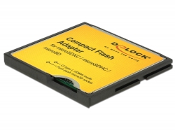
This is the adapter I use and works in every combination. (PPIDE/IDE unbuffered as in rc2014 and buffered.) it is a delock adapter.
Op vrijdag 29 juli 2022 om 11:51:13 UTC+2 schreef Tadeusz Pycio:
Tadeusz Pycio
Aug 9, 2022, 8:06:29 AM8/9/22
to RC2014-Z80
As expected, the SD to CF adapter with buffer (I checked HC, HCT and ACT) is not recognised with the classic /CS, /RD, /WR signal control like Spencer's CF module. This and previous experience rules out the need for it for this adapter (for some CFs it works).

karlab
Aug 9, 2022, 8:43:14 AM8/9/22
to RC2014-Z80
Hi Tadeusz
If your module works with some CF cards it is still useful.
I made many variants of CF cards. I did not find the buffering to give a significant improvement in the robustness of the module.
The best solution was to put resistors on the data lines and caps on the RD/WR lines which was suggested by Bill.
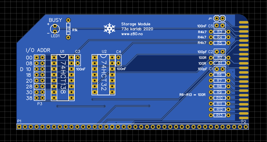
Enclosing pictures of some of my CF modules.
Karl
Tadeusz Pycio
Aug 10, 2022, 7:41:37 AM8/10/22
to RC2014-Z80
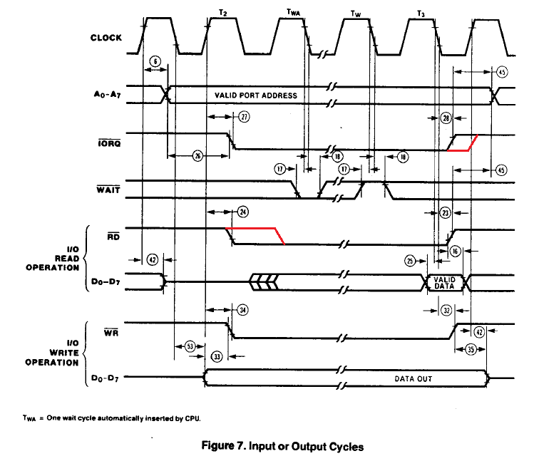
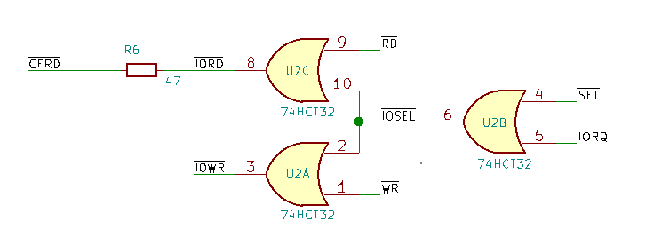
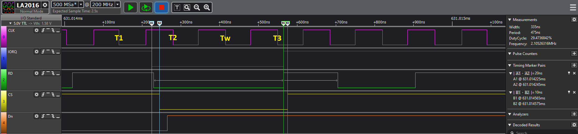
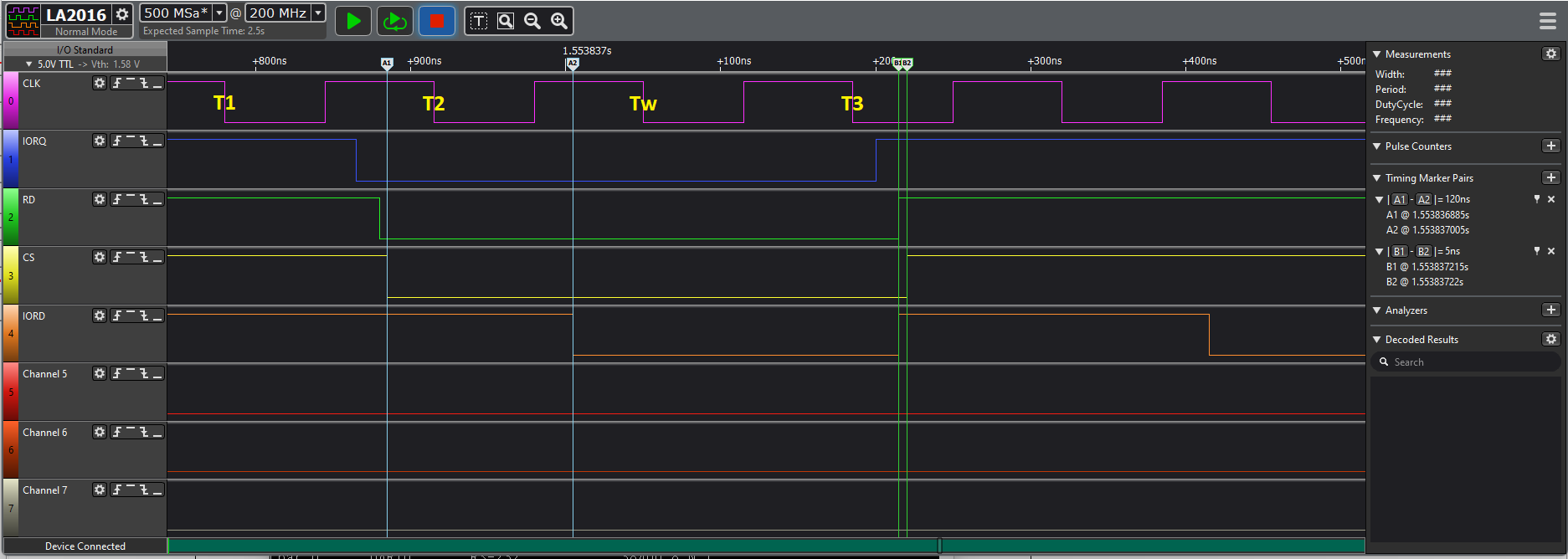
Another clue, I already have confidence that the time dependencies of the control signals are of great importance. Top screenshot of RomWBW startup when I use 74HCT32, below when it is 74ACT32. It's high time to analyse this with an oscilloscope and logic state analyser.
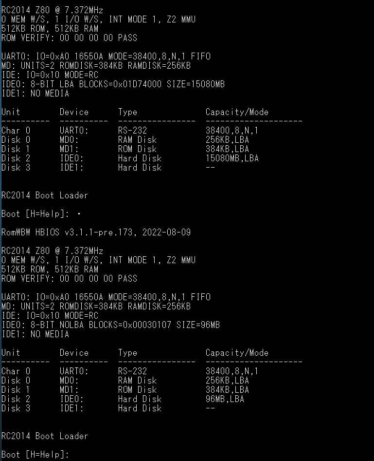
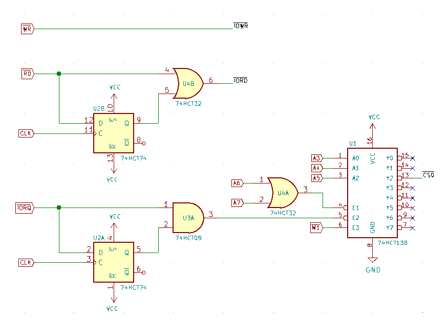
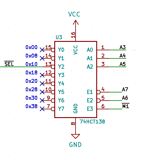
/CFRD is the /IORD input of the CF card, /SEL from the address decoder and it controls the /CE input of the CF card.
Bill Shen
Aug 10, 2022, 1:24:02 PM8/10/22
to RC2014-Z80
How was /SEL generated? Just with addresses and /M1? I assume 15080MB is the correct disk size? Did ACT32 consistently read 96MB disk size. ACT and AC logic are so fast which can generate reflection affecting proper CF access.
Bill
Tadeusz Pycio
Aug 10, 2022, 2:10:14 PM8/10/22
to RC2014-Z80
How was /SEL generated? Just with addresses and /M1? I assume 15080MB is the correct disk size? Did ACT32 consistently read 96MB disk size. ACT and AC logic are so fast which can generate reflection affecting proper CF access.
I made too much of a mental abbreviation. Yes, the /SEL signal is generated as you suggested, the SD card is 16GB and the resistor on the /IORD line is 100R. The results are repeatable, so it will be easy to see the differences, as well as whether there are reflections. My oscilloscope should be back on Friday so I will have more to say.
Bill Shen
Aug 10, 2022, 3:40:32 PM8/10/22
to RC2014-Z80
I did not see a 100pF capacitor to ground on /CFRD. You need the capacitor to form a low-pass filter to attenuate the fast ground bounce generated by the CF access. The ACT32 pushed CF operation near the ragged edge such that a small change can impact CF operation. I would poke around holding a steel needle with fingers and use your body capacitance to find the sensitive circuit.
Bill
Tadeusz Pycio
Aug 11, 2022, 3:35:52 AM8/11/22
to RC2014-Z80
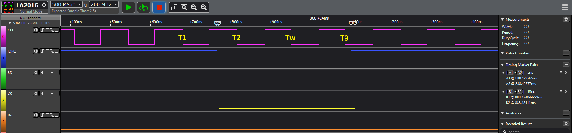
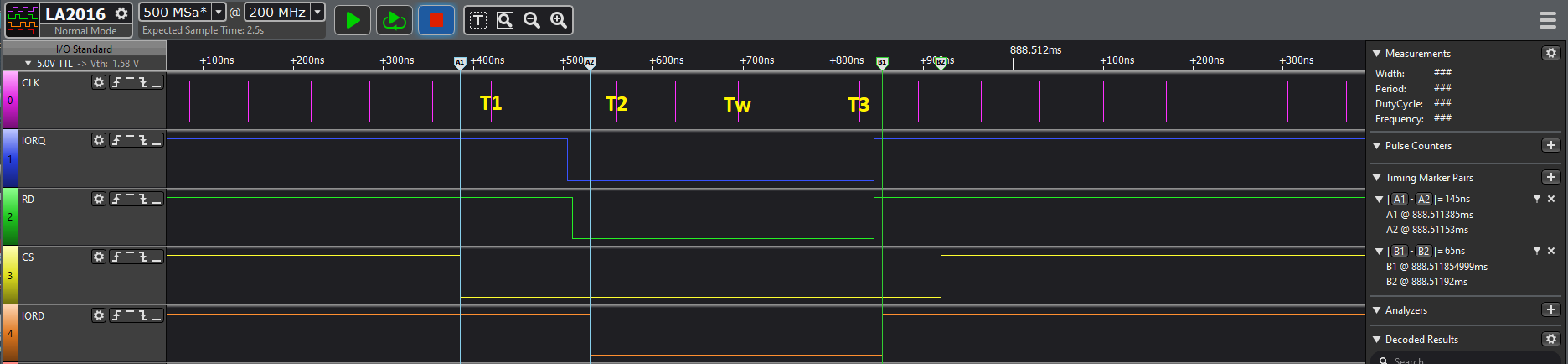
Several time courses for different CF modules. Unfortunately I only have a simple 200MHz analyser at my disposal, so the results will only be indicative. In the first two the /RD signal is also the /IORD signal for the CF card, in the last one it has a dedicated one (according to the schematic from my previous post). It seems that CF cards require the /IORD signal to appear after the /CS has already been established. In the first pass, the /CS signal does not appear until ~15ns after the /RD (/IORD) signal and this module causes the most trouble. A time of max. ~10ns is tolerated by most cards. The timing of the CPU readout itself is the same for all modules. I'm waiting for the oscilloscope, hopefully I'll see more, but the clue of the sequence of /IORD appearing after /CS seems right.
Tadeusz Pycio
Aug 22, 2022, 5:37:05 PM8/22/22
to RC2014-Z80
After a temporary absence due to illness, I'm back with new news of progress. The /RD signal delay allows any CF card to be recognised but there are problems reading it correctly (I need to bridge the buffer). I managed to recognise undetected by all the CF and IDE modules available to me - SanDisk Ultra 2GB. The interesting thing is that the use of /IOWR must be combined with /WR of the processor, the signals /IORQ OR /WR prevent the detection of cards.
Phillip Stevens
Sep 1, 2022, 2:17:20 AM9/1/22
to RC2014-Z80
Tadeusz Pycio wrote:
After a temporary absence due to illness, I'm back with new news of progress.
Glad you're well again.
The /RD signal delay allows any CF card to be recognised but there are problems reading it correctly (I need to bridge the buffer). I managed to recognise undetected by all the CF and IDE modules available to me - SanDisk Ultra 2GB.
The interesting thing is that the use of /IOWR must be combined with /WR of the processor, the signals /IORQ OR /WR prevent the detection of cards.
I started looking at my code for the IDE Hard Drive Module, to see how the timing works there.
Clearly, there's a huge difference using the 82C55 as a latched buffer to drive the IDE interface.
Effectively, I do the /CS by driving the address and this is done a whole 18 clock cycles before the /RD line. On the way out there are 15 cycles before the control /CS is removed.
Code for a Byte read below. The 16-bit Block read is here, and is set up more efficiently, as control is never released and just /RD is toggled for each 16-bit word.
ld a,__IO_PIO_IDE_RD
out (__IO_PIO_IDE_CONFIG),a ;config 8255 chip, read mode
ld a,d
out (__IO_PIO_IDE_CTL),a ;drive address onto control lines
or __IO_IDE_RD_LINE
out (__IO_PIO_IDE_CTL),a ;and assert read pin
in a,(__IO_PIO_IDE_LSB) ;read the lower byte
ld e,a ;save read byte to E
ld a,d
out (__IO_PIO_IDE_CTL),a ;deassert read pin
xor a
out (__IO_PIO_IDE_CTL),a ;deassert all control pins
ld a,e
ret
That is why the IDE Hard Drive Module is very tolerant of different CF Cards, the SD Adapters, and real IDE spinning disks.
The timing is very close to the original IDE PIO Mode 0, and is not "critical" in any way.
For reference, I did some more benchmarking within CP/M, and found it takes 46 seconds to copy a 1MByte file using pip. That's just over 45kByte/s. I think that's pretty good.
About half as fast as copying on FATFS directly. This is caused (in part) by the double buffer copy within the BIOS deblocking code, and then again within the PIP application.
Cheers, Phillip
Tadeusz Pycio
Sep 1, 2022, 3:20:03 AM9/1/22
to RC2014-Z80
Hi Phillip,
True, the IDE module can be considered a reference, as it supports most of the devices connected to it. I want to put a definitive end to the problems associated with the eight-bit CF interface and the only way is through hardware tricks to realise the timings required by these cards. So far I have confirmed that a buffer is not necessary (I only have one CF card that requires it) and the /IORD signal must be delayed with respect to the /CS signal. The work is temporarily suspended as my break has caused a flurry of things I need to finish. I'm also looking forward to rebuilding the test bench, because it's sometimes too unstable. ;-)
True, the IDE module can be considered a reference, as it supports most of the devices connected to it. I want to put a definitive end to the problems associated with the eight-bit CF interface and the only way is through hardware tricks to realise the timings required by these cards. So far I have confirmed that a buffer is not necessary (I only have one CF card that requires it) and the /IORD signal must be delayed with respect to the /CS signal. The work is temporarily suspended as my break has caused a flurry of things I need to finish. I'm also looking forward to rebuilding the test bench, because it's sometimes too unstable. ;-)

Dylan Hall
Sep 2, 2022, 6:55:27 AM9/2/22
to rc201...@googlegroups.com
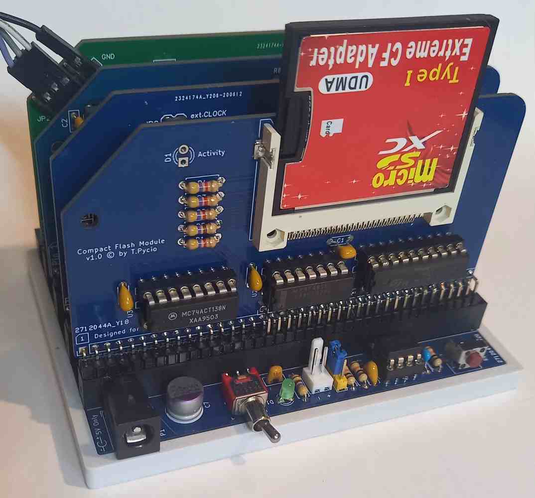
Jumping back to an older post of Philips. The idea of a true IDE CF card adapter really appealed, so...
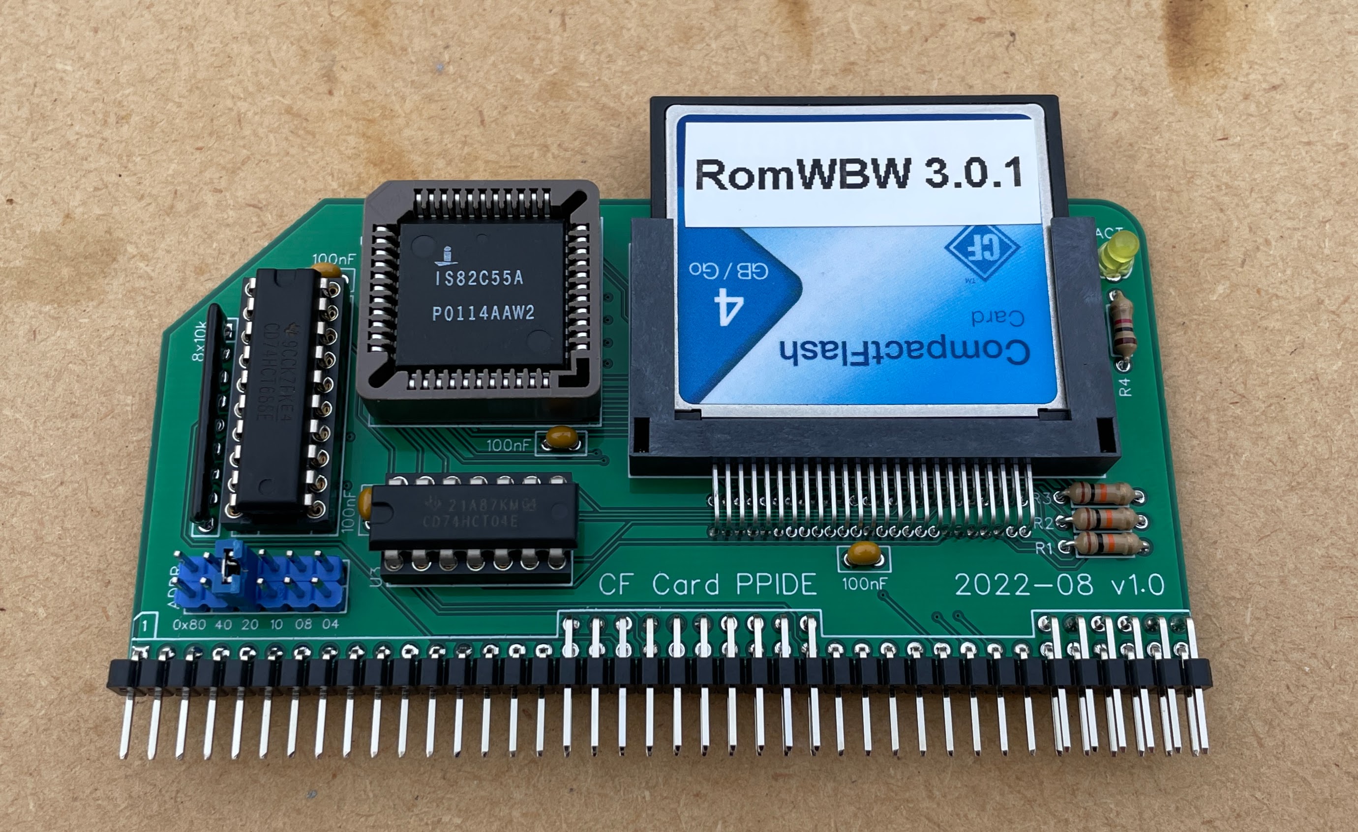
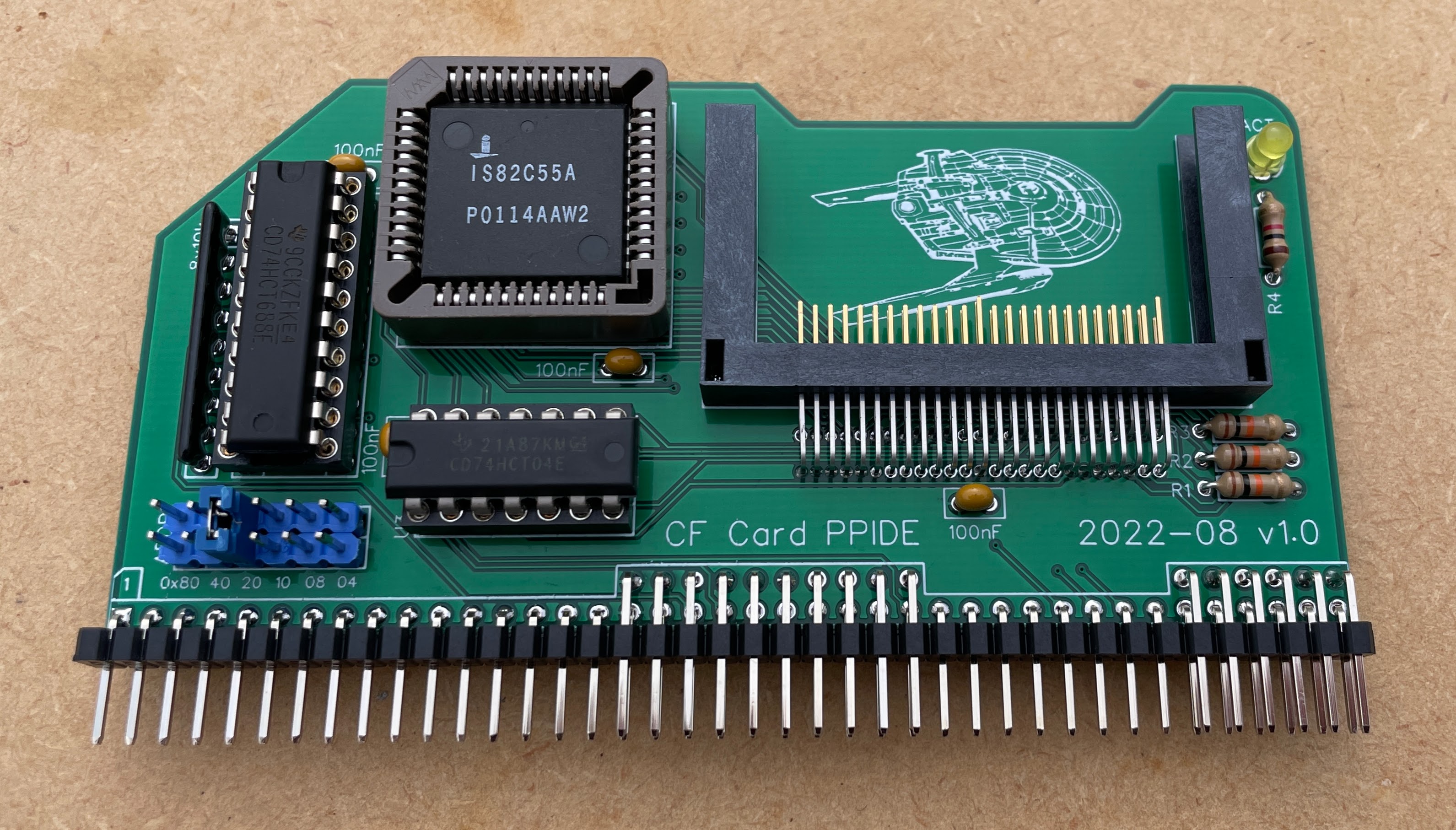
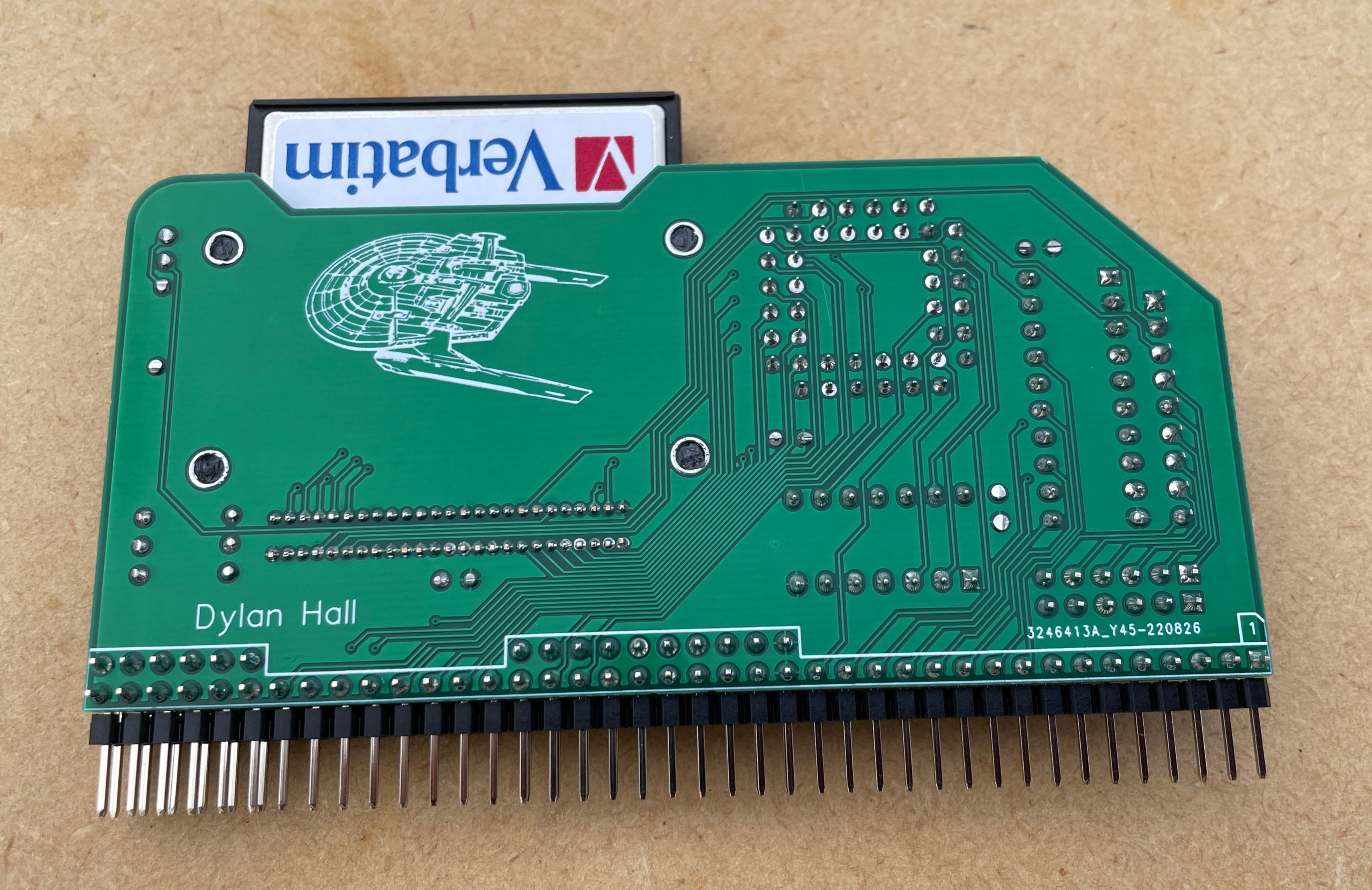
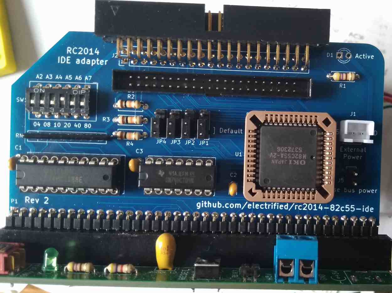
I've mashed together the official CF card and IDE modules along with the through hole CF socket mentioned before.
I'm not sure I've done the right thing with all the CF pins, but it seems to be working nicely with the handful of cards I've tried including one of the SD->CF adapters.
All testing was with RomWBW 3.0.1.
Schematic attached. If anyone with a better grasp of IDE can see any issues that would be much appreciated :)
I'm happy to share gerbers etc if anyone's interested.
Dylan
--
You received this message because you are subscribed to the Google Groups "RC2014-Z80" group.
To unsubscribe from this group and stop receiving emails from it, send an email to rc2014-z80+...@googlegroups.com.
To view this discussion on the web, visit https://groups.google.com/d/msgid/rc2014-z80/6cea7f4d-69b0-44a2-8c91-1fd7fccfdab5n%40googlegroups.com.
Phillip Stevens
Sep 2, 2022, 7:12:38 AM9/2/22
to rc201...@googlegroups.com
Schematic attached. If anyone with a better grasp of IDE can see any issues that would be much appreciated :)I'm happy to share gerbers etc if anyone's interested.Dylan
Hi Dylan,
It looks perfect. Particularly like the beveled cutout to ease access to the CF Card.
I’d love to get a few PCBs. Seeed does 5 minimum, so I’d have some available in Australia.
Cheers, Phillip
Dylan Hall
Sep 2, 2022, 7:30:10 AM9/2/22
to rc201...@googlegroups.com
Gerbers attached. I've exported those from EasyEDA so hopefully they're compatible.
Sorry, I should have added, the board is a 4 layer board. Signals on the top and bottom layers, power and ground on the inner layers.
I'd be happy to send you a board from across the ditch, but I suspect that'll cost about the same as ordering 5 yourself.
I picked up the 82C55A from AliExpress (https://www.aliexpress.com/item/1005003394878019.html). I was a bit wary about their reliability, but surprisingly they all seem to be ok.
I also found what looks like new parts mis-categorised on LCSC (https://www.lcsc.com/product-detail/Programmable-Logic-Device-CPLDs-FPGAs_CHIPLON-CLIS82C55AZ_C437269.html). I've ordered a couple to try but they've not arrived yet.
Dylan
--
You received this message because you are subscribed to the Google Groups "RC2014-Z80" group.
To unsubscribe from this group and stop receiving emails from it, send an email to rc2014-z80+...@googlegroups.com.
To view this discussion on the web, visit https://groups.google.com/d/msgid/rc2014-z80/CAFC0-0X5u6m-b8dLL1t3K7SUcH38uJ-tHxgSjNyBfgyc92TLkg%40mail.gmail.com.
Tadeusz Pycio
Sep 2, 2022, 9:15:57 AM9/2/22
to RC2014-Z80
I've mashed together the official CF card and IDE modules along with the through hole CF socket mentioned before.
Great idea! Solves all known problems with cards. I since I started playing with the 8-bit interface will finish it (someday). I think this combination with PPI is the best solution.
Phillip Stevens
Sep 2, 2022, 9:54:41 PM9/2/22
to RC2014-Z80
Dylan wrote:
Gerbers attached. I've exported those from EasyEDA so hopefully they're compatible.Sorry, I should have added, the board is a 4 layer board. Signals on the top and bottom layers, power and ground on the inner layers.
Excellent. I would have done 4 layer too.
I've ordered 5x from Elecrow this morning. It seemed to go smoothly with your Gerbers. SeeedFusion seems to be down and, well, you snooze you loose.
Will order the parts shortly.
Would you mind checking whether CPM-IDE with your CF-IDE Module, works for you, please?
If you've got a RC2014 Pro or better, you can just burn the SIO ROM and it should just work with a FAT formatted CF Card.
I won't give you any further hints here, so if you run into problems with the documentation please let me know so that I can fix the instructions.
Cheers, Phillip
Dylan Hall
Sep 3, 2022, 6:05:11 AM9/3/22
to rc201...@googlegroups.com
I'm keen to give CPM-IDE a go, however, there is a slight hitch.
The only ROM I have for the Pageable ROM Module is the one-time-programmable 27C512 that came with the kit.
It looks like the local Jaycar has a 27C256 that I think will be suitable so I'll try and grab one when I get a chance.
What I'm wondering is how hard would it be to modify CPM-IDE to work with the 512k ROM/RAM module?
At power up the 512k module has the first 16k of ROM mapped into all four pages (0x000-0x3FFF, 0x4000-0x7FFF, 0x8000-0xBFFF, 0xC000-0xFFFF).
I think the changes would look something like this.
Very early in the boot sequence setup 32k ROM, 32k RAM, e.g.
; setup ROM in bottom 32k
LD A, 0
OUT $78, A
LD A, 1
OUT $79, A
; setup RAM in top 32k
LD A, 32
OUT $7A, A
LD A, 33
OUT $7B, A
; enable paging
LD A, 1
OUT $7C, A
Later on when you normally toggle the PAGE signal, page RAM into the bottom 32k, e.g.
; setup RAM in the bottom 32k
LD A, 34
OUT $78, A
LD A, 35
OUT $79, A
I've had a quick look at the CPM-IDE source, but I'm rather out of my depth. Any pointers where to look would be helpful :)
Thanks,
Dylan
Message has been deleted
Phillip Stevens
Sep 3, 2022, 7:44:16 AM9/3/22
to RC2014-Z80
Dylan wrote:I'm keen to give CPM-IDE a go, however, there is a slight hitch.The only ROM I have for the Pageable ROM Module is the one-time-programmable 27C512 that came with the kit.It looks like the local Jaycar has a 27C256 that I think will be suitable so I'll try and grab one when I get a chance.
I've used Winbond W27C512 and SST 27C256 both from Ali Express. Cheap, and worth the gamble, imho.
What I'm wondering is how hard would it be to modify CPM-IDE to work with the 512k ROM/RAM module?
Pretty easy. I should set up z88dk to support the 512k/512k Module one day, but in the interim there are just two places you need to touch code.1. In the set up for the 64k/64k shadow RAM set up where the code wrapped in __IO_RAM_SHADOW_AVAILABLE can be deleted and replaced by code for the 512k/512k Module.
It would also to remove references to shadow ram asm_shadow_copy and asm_shadow_relocate, as these will no longer exist.
Just delete them out.
I've had a quick look at the CPM-IDE source, but I'm rather out of my depth. Any pointers where to look would be helpful :)
Have a read of this guide. It should cover most of the places where code needs to be adjusted. Start from a nightly or a clone of z88dk, and go from there.
Ok. That's the third time I've typed this.
My next job is to fix the PC so I get longer than 5 minutes between undesired reboots.
Good luck, and let me know of any questions.
Cheers, P.
Dylan Hall
Sep 5, 2022, 2:52:23 AM9/5/22
to rc201...@googlegroups.com
Hi Phillip, I've tracked down a pair of M27C256B (32KB) ROMs and burnt rc2014-sio-cpm22.hex to one of them.
However, something isn't working quite right. I see this when I reset the system:
RC2014 CP/M-IDE
feilipu 2022
> :?
feilipu 2022
> :?
I've swapped everything I can think to swap but the result is consistent. This is with or without a PPIDE module installed (same result for the official module and my CF card version).
If I swap back to the supplied ROM and move the jumpers back I can boot into SCM so I think the system itself is happy.
I'm suspicious of my ROM. I believe it's a 150ns part, so I thought it might be too slow. That said, I halved the clock speed and repeated the tests at 57600 8n2 and got the same result.
I noticed you'd uploaded a new version of the .hex file recently so I've tried that and the version I checked out a couple days ago.
My other thought is that the 27C256 needs different jumper settings than the 27C512. I'll have a dig into that idea later, but for now I'm hoping you'll see the :? output and that will mean something to you :)
Thanks,
Dylan
--
You received this message because you are subscribed to the Google Groups "RC2014-Z80" group.
To unsubscribe from this group and stop receiving emails from it, send an email to rc2014-z80+...@googlegroups.com.
To view this discussion on the web, visit https://groups.google.com/d/msgid/rc2014-z80/977291ed-4e51-457e-9729-a3448210e26en%40googlegroups.com.
Phillip Stevens
Sep 5, 2022, 3:11:25 AM9/5/22
to rc201...@googlegroups.com
On Mon, 5 Sep 2022 at 16:52, Dylan Hall <dy...@deedums.com> wrote:
Hi Phillip, I've tracked down a pair of M27C256B (32KB) ROMs and burnt rc2014-sio-cpm22.hex to one of them.However, something isn't working quite right. I see this when I reset the system:RC2014 CP/M-IDE
feilipu 2022
> :?I've swapped everything I can think to swap but the result is consistent. This is with or without a PPIDE module installed (same result for the official module and my CF card version).If I swap back to the supplied ROM and move the jumpers back I can boot into SCM so I think the system itself is happy.I'm suspicious of my ROM. I believe it's a 150ns part, so I thought it might be too slow. That said, I halved the clock speed and repeated the tests at 57600 8n2 and got the same result.I noticed you'd uploaded a new version of the .hex file recently so I've tried that and the version I checked out a couple days ago.My other thought is that the 27C256 needs different jumper settings than the 27C512. I'll have a dig into that idea later, but for now I'm hoping you'll see the :? output and that will mean something to you :)Thanks,Dylan
It is happy and waiting for you to type a : into the port you’re active on.
Then it will continue.
The TTY port has no echo. It relies on local echo. The CON port has echo turned on. Baud. 115200 8n2.
Dylan Hall
Sep 5, 2022, 6:29:32 AM9/5/22
to rc201...@googlegroups.com
Sorry, as soon as I read your reply I remembered reading that in the instructions. RTFM :)
I think I'm largely there... just some odd behaviour I can't quite understand.
I've connected an FTDI adapter to both of the serials. At power up I see the :? prompt on both.
If I type : into port A I'm into the monitor. For example:
RC2014 CP/M-IDE
feilipu 2022
> :? :-)
> help
RC2014 - CP/M IDE Monitor v2.2
The following functions are built in:
cpm [file][][][] - initiate CP/M with up to 4 drive files
mount [option] - mount a FAT file system
ls [path] - directory listing
cd [path] - change the current working directory
pwd - show the current working directory
ds - disk status
dd [sector] - disk dump, sector in decimal
md [origin] - memory dump, origin in hexadecimal
help - this is it
exit - exit and restart
> mount
rc=0 FR_OK
> ds
FAT type = FAT32
Bytes/Cluster = 4096
Number of FATs = 2
Root DIR entries = 0
Sectors/FAT = 7608
Number of clusters = 973454
Volume start (lba) = 2048
FAT start (lba) = 2080
DIR start (lba,cluster) = 2
Data start (lba) = 17296
> ls
----A 2022/09/05 05:22 8388608 BBCBASIC.CPM
----A 2022/09/05 05:23 8388608 HITECHC.CPM
----A 2022/09/05 05:23 8388608 MSBASCOM.CPM
----A 2022/09/05 05:23 8388608 MSCOBOL.CPM
----A 2022/09/05 05:23 8388608 NZCOM.CPM
----A 2022/09/05 05:23 8388608 PLI.CPM
----A 2022/09/05 05:23 8388608 SLRTOO~1.CPM
----A 2022/09/05 05:23 8388608 SLRTOOL.CPM
----A 2022/09/05 05:23 8388608 SYS.CPM
----A 2022/09/05 05:24 8388608 TEMPLATE.CPM
----A 2022/09/05 05:24 8388608 TURBOP.CPM
----A 2022/09/05 05:24 8388608 USER.CPM
----A 2022/09/05 05:24 8388608 ZORK.CPM
13 File(s), 109051904 bytes total
0 Dir(s), 3878211584 bytes free
> cpm sys.cpm
Opening "sys.cpm" at LBA 148376feilipu 2022
> :? :-)
> help
RC2014 - CP/M IDE Monitor v2.2
The following functions are built in:
cpm [file][][][] - initiate CP/M with up to 4 drive files
mount [option] - mount a FAT file system
ls [path] - directory listing
cd [path] - change the current working directory
pwd - show the current working directory
ds - disk status
dd [sector] - disk dump, sector in decimal
md [origin] - memory dump, origin in hexadecimal
help - this is it
exit - exit and restart
> mount
rc=0 FR_OK
> ds
FAT type = FAT32
Bytes/Cluster = 4096
Number of FATs = 2
Root DIR entries = 0
Sectors/FAT = 7608
Number of clusters = 973454
Volume start (lba) = 2048
FAT start (lba) = 2080
DIR start (lba,cluster) = 2
Data start (lba) = 17296
> ls
----A 2022/09/05 05:22 8388608 BBCBASIC.CPM
----A 2022/09/05 05:23 8388608 HITECHC.CPM
----A 2022/09/05 05:23 8388608 MSBASCOM.CPM
----A 2022/09/05 05:23 8388608 MSCOBOL.CPM
----A 2022/09/05 05:23 8388608 NZCOM.CPM
----A 2022/09/05 05:23 8388608 PLI.CPM
----A 2022/09/05 05:23 8388608 SLRTOO~1.CPM
----A 2022/09/05 05:23 8388608 SLRTOOL.CPM
----A 2022/09/05 05:23 8388608 SYS.CPM
----A 2022/09/05 05:24 8388608 TEMPLATE.CPM
----A 2022/09/05 05:24 8388608 TURBOP.CPM
----A 2022/09/05 05:24 8388608 USER.CPM
----A 2022/09/05 05:24 8388608 ZORK.CPM
13 File(s), 109051904 bytes total
0 Dir(s), 3878211584 bytes free
> cpm sys.cpm
Initialised CP/M
This is where it gets weird. The A> prompt then appears on serial port B. Issuing commands like dir return garbage (but not random, for example the minicom version string appears in the output). e.g output from port B:
RC2014 CP/M-IDE
feilipu 2022
> :?
feilipu 2022
> :?
A>
A>
A>dir
A: D.>S0! q : MFm^! 9I : !IMU!2 W : w~#.Lzp !PM
A>inicom2.7.1
INICOM2.7.1?
A>
A>dir
A: D.>S0! q : MFm^! 9I : !IMU!2 W : w~#.Lzp !PM
A>inicom2.7.1
INICOM2.7.1?
A>
A>b:
Bdos Err On B: Select
A>b:
Bdos Err On B: Select
It gets interesting when I try to access a non-existent drive, e.g. b: above. At this point there appears to be a timeout, then the A> prompt appears on serial port A. At this point everything appears to be working nicely, e.g output from port A:
A>
A>dir
A: ASM COM : CAL COM : DDIR COM : DDT COM
A: DUMP COM : ED COM : ERASE SUB : FULLPRMP SUB
A: INFO COM : KERMIT COM : LOAD COM : LS COM
A: LUA COM : LU COM : MAC COM : MBASIC COM
A: MLOAD COM : MOVCPM COM : NORMPRMP SUB : NSWP COM
A: PIP COM : PLAYER COM : SD COM : SH COM
A: SH OVR : SHSAVE COM : STAT COM : SUBMIT COM
A: SURVEY COM : SYSGEN COM : TE COM : UNARC COM
A: UNCR COM : USQ COM : XMODEM COM : XSUB COM
A: Z80ASM COM : ZEXALL COM : ZEXDOC COM : ZSID COM
A: ZTRAN COM
A>
The behaviour is the same with the official IDE module or my cf card module.
Another odd behaviour is the hardware reset no longer appears to work, hitting reset locks up the system. I'm guessing the system is picking up where it left off in some fashion after a reset and is unhappy.
Repeating the above but entering : on serial port B works better but still not quite right. e.g.
RC2014 CP/M-IDE
feilipu 2022
> :? :-)
> mount
rc=0 FR_OK
> cpm sys.cpm
Opening "sys.cpm" at LBA 148376
Initialised CP/M
A>dir
A: D.>S0! q : MFm^! 9I : !IMU!2 WM
A>inicom2.7.1
INICOM2.7.1?
A>d:
Bdos Err On D: Select
A>
A>dir
A: ASM COM : CAL COM : DDIR COM : DDT COM
A: DUMP COM : ED COM : ERASE SUB : FULLPRMP SUB
A: INFO COM : KERMIT COM : LOAD COM : LS COM
A: LUA COM : LU COM : MAC COM : MBASIC COM
A: MLOAD COM : MOVCPM COM : NORMPRMP SUB : NSWP COM
A: PIP COM : PLAYER COM : SD COM : SH COM
A: SH OVR : SHSAVE COM : STAT COM : SUBMIT COM
A: SURVEY COM : SYSGEN COM : TE COM : UNARC COM
A: UNCR COM : USQ COM : XMODEM COM : XSUB COM
A: Z80ASM COM : ZEXALL COM : ZEXDOC COM : ZSID COM
A: ZTRAN COM
A>
Any thoughts?
Thanks,
Dylan
--
You received this message because you are subscribed to the Google Groups "RC2014-Z80" group.
To unsubscribe from this group and stop receiving emails from it, send an email to rc2014-z80+...@googlegroups.com.
To view this discussion on the web, visit https://groups.google.com/d/msgid/rc2014-z80/CAFC0-0VfkBXx7%2B93LaoRsqLaUt50-eVVLj62srJob_mETOEeOw%40mail.gmail.com.
Phillip Stevens
Sep 5, 2022, 7:46:58 AM9/5/22
to RC2014-Z80
Dylan wrote:
Sorry, as soon as I read your reply I remembered reading that in the instructions. RTFM :)I think I'm largely there... just some odd behaviour I can't quite understand.
Looks like you are there.
And most importantly your PPI CF Module works fine. :-)
That makes me happy to see.
I've connected an FTDI adapter to both of the serials. At power up I see the :? prompt on both.If I type : into port A I'm into the monitor. For example:
Yes. On boot it sends characters to both ports, and will choose one to be the monitor console based on input of the :
This also sets the BIOS IO Byte so that CP/M will talk to the right port too.
RC2014 CP/M-IDE
feilipu 2022
> :? :-)
> help
RC2014 - CP/M IDE Monitor v2.2
The following functions are built in:
cpm [file][][][] - initiate CP/M with up to 4 drive files
mount [option] - mount a FAT file system
ls [path] - directory listing
cd [path] - change the current working directory
pwd - show the current working directory
ds - disk status
dd [sector] - disk dump, sector in decimal
md [origin] - memory dump, origin in hexadecimal
help - this is it
exit - exit and restart
> mount
mount is optional command, as both ls and cpm commands do an initial mount themselves.
I often just do mount when testing to ensure that a disk is properly formatted.
rc=0 FR_OK
> ds
FAT type = FAT32
Bytes/Cluster = 4096
> ls
----A 2022/09/05 05:22 8388608 BBCBASIC.CPM
----A 2022/09/05 05:23 8388608 HITECHC.CPM
----A 2022/09/05 05:23 8388608 MSBASCOM.CPM
13 File(s), 109051904 bytes total
0 Dir(s), 3878211584 bytes free
> cpm sys.cpm
Opening "sys.cpm" at LBA 148376
Initialised CP/M
This is where it gets weird. The A> prompt then appears on serial port B. Issuing commands like dir return garbage (but not random, for example the minicom version string appears in the output). e.g output from port B:
The A> prompt should appear on the port that you used to enter the commands on.
If not, then a bug has crept in. It used to work like that.
Firstly, try a FTDI adapter on just one of the two ports. Shouldn't matter which one.
But note one of them (port B) will not echo your commands.
It is set up like an old fashioned TTY without remote echo. Old TTY didn't do remote echo to save sending Bytes across 110 Baud.
Just configure local echo on that port B.
When you're in CP/M the two ports should behave normally. One as CON: the other as TTY:
You can then map the ports as you desire using the CP/M stat command.
RC2014 CP/M-IDEfeilipu 2022
> :?A>
A>
A>dir
A: D.>S0! q : MFm^! 9I : !IMU!2 W : w~#.Lzp !PM
A>inicom2.7.1
INICOM2.7.1?A>
If you are doing Carriage Return - New Line with your terminal you will have issues. CP/M just likes to see JUST a Carriage Return (CR).
The monitor is ambivalent about CR, or NL, or CR+NL. But unfortunately CP/M isn't so open minded.
Otherwise, seeing this junk from CP/M is concerning, as it means something is wrong with the serial connection.
Either the terminal is being overrun, or something's wrong with the SIO interface, as it is being transmitted by the RC2014.
Please check the CR situation, and let me know.
A>b:
Bdos Err On B: Select
You are getting an error here because you didn't specify a B: drive "drive file".
Your CPM command should look like:
cpm filefor.a filefor.B filefor.C filefor.D
i.e. for example
cpm sys.cpm zork.cpm hitechc.cpm user.cpm
to get the maximum of 4 active drives.
To change drives, just EXIT and then reload CPM.
Later if you can be bothered, you can use the yash shell to mount and change drives from within CP/M.
This program can also copy, duplicate, and delete FATFS files and directories.
After time passes, CP/M will return to the active drive when you select a non existent drive.
Again here the B: drive hasn't been specified, nor have C: or D: so it will return you to the valid A: drive.
Cheers, Phillip
Dylan Hall
Sep 5, 2022, 9:46:17 PM9/5/22
to rc201...@googlegroups.com
I don't think I did a very good job of explaining what I was seeing.
I'm aware that a drive won't work if I've not specified a disk image for it.
The behavior I was trying to highlight is that running "dir" returns garbage text every time it's run until I access a non-existent drive, then it starts working.
I can't tell if it's a problem with the data coming from the disk or with the way the serial port is presenting it.
This evening I'll try again, this time I'll try running a command on the disk (for example launching zork) which I'm hoping will be enough to tell if it's an issue reading the disk or the serial stream being corrupted.
I'll also check on the CR/LF settings (I'm pretty sure it's the minicom defaults, but I've no idea what those are).
Dylan
--
You received this message because you are subscribed to the Google Groups "RC2014-Z80" group.
To unsubscribe from this group and stop receiving emails from it, send an email to rc2014-z80+...@googlegroups.com.
To view this discussion on the web, visit https://groups.google.com/d/msgid/rc2014-z80/edc7c08f-9a31-401c-b757-f7f77fe518cbn%40googlegroups.com.
Phillip Stevens
Sep 5, 2022, 9:49:18 PM9/5/22
to RC2014-Z80
Dylan,
thinking about this, I've added some further notes (and inline).
1. make sure your "cp/m files" are contiguous. Perhaps if you're unzipping them on the drive itself, they are being allocated non-contiguous. The easiest way to ensure this is to copy the file from your PC drive.
2. updated the instructions. I was being too terse with the "cpm" command instruction.
3. the odd reboot is caused because the RAM is holding a "canary" to signal that BIOS has been loaded, during the normal CP/M reload process (which also calls JP 0). I just keep a digital I/O card plugged in to put some load on the power supply capacitors and ensure the RAM is powered down during the reboot. Otherwise a power cycle is needed (or just type EXIT within CP/M).
Phillip wrote:
RC2014 CP/M-IDE
feilipu 2022
> :?A>
A>
A>dir
A: D.>S0! q : MFm^! 9I : !IMU!2 W : w~#.Lzp !PM
A>inicom2.7.1
INICOM2.7.1?A>
Otherwise, seeing this junk from CP/M is concerning, as it means something is wrong with the serial connection.Either the terminal is being overrun, or something's wrong with the SIO interface, as it is being transmitted by the RC2014.Please check the CR situation, and let me know.
Just thinking this could be happening if the CP/M file is not contiguous on the drive. Given the size of the files (8MB) versus the size of your media (4GB), this should not ever be an issue.
But, if you used unzip and it doesn't allocate all the file at once, perhaps something weird is happening?
Unzip the examples on your PC, and then just copy the complete 8MB files over to your CF card.
A>b:Bdos Err On B: SelectYou are getting an error here because you didn't specify a B: drive "drive file".Your CPM command should look like:cpm filefor.a filefor.B filefor.C filefor.Di.e. for examplecpm sys.cpm zork.cpm hitechc.cpm user.cpmto get the maximum of 4 active drives.
I've fixed the documentation to try to make this point clearer.
Dylan Hall
Sep 5, 2022, 10:16:37 PM9/5/22
to rc201...@googlegroups.com
I don't think the files will be fragmented. The procedure I followed was:
git clone the repo
unzip all the CPM disk images on the local disk
use gparted to partition/format the CF card
copy *.zip to the CF card
Is there a trivial way to inspect the FAT table to ensure the files are contiguous?
My only thought is that gparted likes to leave 1MB of empty space at the start of the disk when partitioning it. I don't imagine this would have any impact but I could try again setting the offset to zero.
The hardware reset and the canary value makes sense. You had mentioned that in the docs. I won't worry about this :)
I'll let you know how I get on with my tinkering this evening.
Dylan
--
You received this message because you are subscribed to the Google Groups "RC2014-Z80" group.
To unsubscribe from this group and stop receiving emails from it, send an email to rc2014-z80+...@googlegroups.com.
To view this discussion on the web, visit https://groups.google.com/d/msgid/rc2014-z80/336055e9-5287-4636-b58e-82e35a2648fdn%40googlegroups.com.
Phillip Stevens
Sep 5, 2022, 10:47:59 PM9/5/22
to rc201...@googlegroups.com
Dylan wrote:
I don't think the files will be fragmented. The procedure I followed was:git clone the repounzip all the CPM disk images on the local diskuse gparted to partition/format the CF cardcopy *.zip to the CF cardIs there a trivial way to inspect the FAT table to ensure the files are contiguous?My only thought is that gparted likes to leave 1MB of empty space at the start of the disk when partitioning it. I don't imagine this would have any impact but I could try again setting the offset to zero.
It doesn’t care how it is formatted. Even FAT16 is ok. I usually leave 8 MB unformatted in CF and SSD so that is no issue.
The hardware reset and the canary value makes sense. You had mentioned that in the docs. I won't worry about this :)I'll let you know how I get on with my tinkering this evening.Dylan
Thanks. P.
Phillip Stevens
Sep 6, 2022, 1:32:11 AM9/6/22
to RC2014-Z80
Dylan wrote:
I don't think the files will be fragmented. The procedure I followed was:git clone the repounzip all the CPM disk images on the local diskuse gparted to partition/format the CF cardcopy *.zip to the CF card
You mean the *.cpm files, right?
Is there a trivial way to inspect the FAT table to ensure the files are contiguous?
Oddly enough there is actually a FATFS application example to do exactly this test.
If it turns out that fragmented files was your issue, then it would be worth adding this as a "check" before allowing them as valid CP/M drive files.
Otherwise, it could just be an additional shell function. I think there might be space available if needed.
Cheers, Phillip
Dylan Hall
Sep 6, 2022, 1:41:58 AM9/6/22
to rc201...@googlegroups.com
Sorry, yes, *.cpm, not *.zip :)
Dylan
--
You received this message because you are subscribed to the Google Groups "RC2014-Z80" group.
To unsubscribe from this group and stop receiving emails from it, send an email to rc2014-z80+...@googlegroups.com.
To view this discussion on the web, visit https://groups.google.com/d/msgid/rc2014-z80/51a477c7-ada1-4a19-a0dd-8cd2e00c4f79n%40googlegroups.com.
Phillip Stevens
Sep 6, 2022, 2:43:14 AM9/6/22
to RC2014-Z80
Dylan wrote:Is there a trivial way to inspect the FAT table to ensure the files are contiguous?Oddly enough there is actually a FATFS application example to do exactly this test.If it turns out that fragmented files was your issue, then it would be worth adding this as a "check" before allowing them as valid CP/M drive files.Otherwise, it could just be an additional shell function. I think there might be space available if needed.
Just to see what happens. I've added the function to the code.
It does cost quite a bit of time at at CP/M load time, as all of each file needs to be seeked through.
I've attached the HEX file to here (for SIO serial) so that you can test with it.
Let me know if you think the test is worth having as an option.
Cheers, Phillip
Phillip Stevens
Sep 6, 2022, 6:07:00 AM9/6/22
to RC2014-Z80
Phillip wrote:
Dylan wrote:Is there a trivial way to inspect the FAT table to ensure the files are contiguous?Oddly enough there is actually a FATFS application example to do exactly this test.
Just to see what happens. I've added the function to the code.It does cost quite a bit of time at at CP/M load time, as all of each file needs to be seeked through.
I've added a new function frag to the shell system functions which can check whether a file is fragmented or contiguous.
It will report OK if the file is not fragmented.
Since this attribute will not change once a CP/M drive file is stored on the drive it makes sense to only check it once (rather than every time CP/M is loaded).
I think that's a worthwhile confidence building addition.
Perhaps pull repo again and use the new HEX file to test it instead?
Cheers, Phillip
Dylan Hall
Sep 6, 2022, 6:28:41 AM9/6/22
to rc201...@googlegroups.com
That's a nice addition.
I've got the ROM chip under a UV lamp at the moment but it's not really designed for erasing chips so it's taking a while. At this rate it'll be tomorrow before I can do any useful tests.
Dylan
--
You received this message because you are subscribed to the Google Groups "RC2014-Z80" group.
To unsubscribe from this group and stop receiving emails from it, send an email to rc2014-z80+...@googlegroups.com.
To view this discussion on the web, visit https://groups.google.com/d/msgid/rc2014-z80/e9fa477a-9db9-4ac3-9c49-8cdd3361688en%40googlegroups.com.
Dylan Hall
Sep 7, 2022, 5:21:48 AM9/7/22
to rc201...@googlegroups.com
I've made a little progress. The frag command is working nicely, e.g.
RC2014 CP/M-IDE
feilipu 2022
> :-)
feilipu 2022
> :-)
> ls
----A 2022/09/05 05:22 8388608 BBCBASIC.CPM
----A 2022/09/05 05:23 8388608 HITECHC.CPM
----A 2022/09/05 05:23 8388608 MSBASCOM.CPM
----A 2022/09/05 05:23 8388608 MSCOBOL.CPM
----A 2022/09/05 05:23 8388608 NZCOM.CPM
----A 2022/09/05 05:23 8388608 PLI.CPM
----A 2022/09/05 05:23 8388608 SLRTOO~1.CPM
----A 2022/09/05 05:23 8388608 SLRTOOL.CPM
----A 2022/09/05 05:23 8388608 SYS.CPM
----A 2022/09/05 05:24 8388608 TEMPLATE.CPM
----A 2022/09/05 05:24 8388608 TURBOP.CPM
----A 2022/09/05 05:24 8388608 USER.CPM
----A 2022/09/05 05:24 8388608 ZORK.CPM
13 File(s), 109051904 bytes total
0 Dir(s), 3878211584 bytes free
0 Dir(s), 3878211584 bytes free
> frag sys.cpm
Checking "sys.cpm" at LBA 148376 is OK
Checking "sys.cpm" at LBA 148376 is OK
I've switched to an ACIA serial module (SC139) as I wanted to rule out issues with the SIO.
I'm still seeing the curious behavior with disk access after startup. e.g.
> cpm sys.cpm
Opening "sys.cpm" at LBA 148376
Initialised CP/M
A>dir
Opening "sys.cpm" at LBA 148376
Initialised CP/M
A>dir
A: S0!Xr D : !9
7 mBZ : !fW\ tm : Lr!eQ r
A: S0!Xr D : !9
7 mBZ : !fW\ tm : Lr!eQ r
A: S0!Xr D : !9
7 mBZ : !fW\ tm : Lr!eQ r
A: S0!Xr D : !9
7 mBZ : !fW\ tm : Lr!eQ r
A: S0!Xr D : !9
7 mBZ : !fW\ tm : Lr!eQ r
A: S0!Xr D : !9
7 mBZ : !fW\ tm : Lr!eQ r
A: S0!Xr D : !9
7 mBZ : !fW\ tm : Lr!eQ r
A: S0!Xr D : !9
7 mBZ : !fW\ tm : Lr!eQ r
A: S0!Xr D : !9
7 mBZ : !fW\ tm : Lr!eQ r
A: S0!Xr D : !9
7 mBZ : !fW\ tm : Lr!eQ r
A: S0!Xr D
A>
A>dir
A: S0!Xr D : !9
7 mBZ : !fW\ tm : Lr!eQ r
A: S0!Xr D : !9
7 mBZ : !fW\ tm : Lr!eQ r
A: S0!Xr D : !9
7 mBZ : !fW\ tm : Lr!eQ r
A: S0!Xr D : !9
7 mBZ : !fW\ tm : Lr!eQ r
A: S0!Xr D : !9
7 mBZ : !fW\ tm : Lr!eQ r
A: S0!Xr D : !9
7 mBZ : !fW\ tm : Lr!eQ r
A: S0!Xr D : !9
7 mBZ : !fW\ tm : Lr!eQ r
A: S0!Xr D : !9
7 mBZ : !fW\ tm : Lr!eQ r
A: S0!Xr D : !9
7 mBZ : !fW\ tm : Lr!eQ r
A: S0!Xr D : !9
7 mBZ : !fW\ tm : Lr!eQ r
A: S0!Xr D
A>
7 mBZ : !fW\ tm : Lr!eQ r
A: S0!Xr D : !9
7 mBZ : !fW\ tm : Lr!eQ r
A: S0!Xr D : !9
7 mBZ : !fW\ tm : Lr!eQ r
A: S0!Xr D : !9
7 mBZ : !fW\ tm : Lr!eQ r
A: S0!Xr D : !9
7 mBZ : !fW\ tm : Lr!eQ r
A: S0!Xr D : !9
7 mBZ : !fW\ tm : Lr!eQ r
A: S0!Xr D : !9
7 mBZ : !fW\ tm : Lr!eQ r
A: S0!Xr D : !9
7 mBZ : !fW\ tm : Lr!eQ r
A: S0!Xr D : !9
7 mBZ : !fW\ tm : Lr!eQ r
A: S0!Xr D : !9
7 mBZ : !fW\ tm : Lr!eQ r
A: S0!Xr D
A>
A>dir
A: S0!Xr D : !9
7 mBZ : !fW\ tm : Lr!eQ r
A: S0!Xr D : !9
7 mBZ : !fW\ tm : Lr!eQ r
A: S0!Xr D : !9
7 mBZ : !fW\ tm : Lr!eQ r
A: S0!Xr D : !9
7 mBZ : !fW\ tm : Lr!eQ r
A: S0!Xr D : !9
7 mBZ : !fW\ tm : Lr!eQ r
A: S0!Xr D : !9
7 mBZ : !fW\ tm : Lr!eQ r
A: S0!Xr D : !9
7 mBZ : !fW\ tm : Lr!eQ r
A: S0!Xr D : !9
7 mBZ : !fW\ tm : Lr!eQ r
A: S0!Xr D : !9
7 mBZ : !fW\ tm : Lr!eQ r
A: S0!Xr D : !9
7 mBZ : !fW\ tm : Lr!eQ r
A: S0!Xr D
A>
A>b:
Bdos Err On B: Select
A>
A>dir
A: ASM COM : CAL COM : DDIR COM : DDT COM
A: DUMP COM : ED COM : ERASE SUB : FULLPRMP SUB
A: INFO COM : KERMIT COM : LOAD COM : LS COM
A: LUA COM : LU COM : MAC COM : MBASIC COM
A: MLOAD COM : MOVCPM COM : NORMPRMP SUB : NSWP COM
A: PIP COM : PLAYER COM : SD COM : SH COM
A: SH OVR : SHSAVE COM : STAT COM : SUBMIT COM
A: SURVEY COM : SYSGEN COM : TE COM : UNARC COM
A: UNCR COM : USQ COM : XMODEM COM : XSUB COM
A: Z80ASM COM : ZEXALL COM : ZEXDOC COM : ZSID COM
A: ZTRAN COM
A>
A>stat
A: R/W, Space: 7736k
A: R/W, Space: 7736k
As before, running dir results in garbage output each time it's run. After trying to access an unmapped drive everything starts working.
From this point it's working really nicely :)
If I try running a program from disk immediately after startup it returns to the monitor, e.g.
RC2014 CP/M-IDE
feilipu 2022
> :-)
feilipu 2022
> :-)
> cpm sys.cpm
Opening "sys.cpm" at LBA 148376
Initialised CP/M
A>stat
RC2014 CP/M-IDE
feilipu 2022
> :-)
RC2014 CP/M-IDE
feilipu 2022
> :-)
I've tried both minicom and picocom and I think they're only sending CR, but the settings are a little unclear so it's possible this is still wrong.
Thanks,
Dylan
Phillip Stevens
Sep 7, 2022, 6:11:14 AM9/7/22
to RC2014-Z80
This is really odd. All the failure modes I can think of have been ruled out once you see the CP/M A> prompt.
The disk access hardware and software has been long proven (which is your new piece of hardware).
The serial ports are working (both ACIA and SIO), because you can see stuff.
There's no RAM/ROM toggling at this point.
The failure is after CP/M is loaded. So, I've got no clue currently as to what it might be.
Perhaps try ^C at the A> prompt as a remedy for the symptom (but not the cause).
That will relog the drives, but whether that helps or not is unknown.
Cheers, Phillip
If I try running a program from disk immediately after startup it returns to the monitor, e.g.RC2014 CP/M-IDE
feilipu 2022
> :-)
> cpm sys.cpm
Opening "sys.cpm" at LBA 148376
Initialised CP/MA>stat
RC2014 CP/M-IDE
feilipu 2022
> :-)
I've tried both minicom and picocom and I think they're only sending CR, but the settings are a little unclear so it's possible this is still wrong.
On Ubuntu I use GTKTerm for most things, as it supports colour strings (mandelbrot) and control characters and direct toggling of DTR/RTS etc.
But when I want to do C/asm programming I use moserial, as it supports XMODEM so I can quickly and simply upload my compiled .COM files to run them on hardware (rather than a simulator).
Both available on via apt.
Cheers, Phillip
Dylan Hall
Sep 7, 2022, 6:23:35 AM9/7/22
to rc201...@googlegroups.com
The ^C fixes the issue :)
I'll take a look at the other terminal programs tomorrow.
Thanks,
Dylan
--
You received this message because you are subscribed to the Google Groups "RC2014-Z80" group.
To unsubscribe from this group and stop receiving emails from it, send an email to rc2014-z80+...@googlegroups.com.
To view this discussion on the web, visit https://groups.google.com/d/msgid/rc2014-z80/409b1004-aef3-4f6e-921c-a8acd776bb80n%40googlegroups.com.
Phillip Stevens
Sep 7, 2022, 8:37:47 AM9/7/22
to RC2014-Z80
Dylan wrote:
The ^C fixes the issue :)
Well that's something at least.
I've had a poke about with the ALOCVECT setting in BDOS and changed it a bit, but I couldn't find anything that might be related to the problem.
No need to burn a new ROM, unless you want to.
Do you still have this issue with the standard IDE drive, too?
Cheers, P
Dylan Hall
Sep 7, 2022, 4:14:30 PM9/7/22
to rc201...@googlegroups.com
Yes, the issue still occurs with the official IDE module. I’ve tried a 4GB CF card, and two types of SD card adapters. The results are consistent.
I’m wondering if something is different about the power on state of my setup. The unused portion at the end of my ROM chip is all 1’s. But that seems unlikely to have any impact. Could there be an uninitialised variable or buffer that’s getting a different value on power up?
Thanks
Dylan
--
You received this message because you are subscribed to the Google Groups "RC2014-Z80" group.
To unsubscribe from this group and stop receiving emails from it, send an email to rc2014-z80+...@googlegroups.com.
To view this discussion on the web, visit https://groups.google.com/d/msgid/rc2014-z80/cc1fd01b-eb89-429e-97bb-ae50307962ean%40googlegroups.com.
Phillip Stevens
Sep 7, 2022, 8:12:38 PM9/7/22
to RC2014-Z80
Dylan wrote:
Yes, the issue still occurs with the official IDE module. I’ve tried a 4GB CF card, and two types of SD card adapters. The results are consistent.
Ok that’s good news. Rules out your PPI IDE and storage devices.
I’m wondering if something is different about the power on state of my setup. The unused portion at the end of my ROM chip is all 1’s. But that seems unlikely to have any impact. Could there be an uninitialised variable or buffer that’s getting a different value on power up?
Yes. I think you’re right. It is some kind of initialisation problem. Particularly as relogging the drives cures it.
Yesterday, I suspected the BIOS dirbf and hstbuf. I recently moved them to be uninitialised to reduce boot time. So you could grab a ROM from last week to check that possibility.
But, last night I dug into the BDOS and BIOS processes and hstbuf is filled before use, and that’s is where the BDOS DIRBUF pointer is also filled.
So I’m not sure there’s a root cause arising from that.
I’ll go to my hardware archive and try to set up a vanilla Plus / Pro system to see if I can replicate the issue.
My normal system has some power hungry Modules that might tend to automatically zero RAM on Reset. So will see if that’s the root cause by replacing with standard Modules and using USB power from Serial Module.
Which Modules are in your system?
How do you power it? USB or Barrel Adapter?
Sure we’ll find it. And remain v. happy about your PPI CF Module. Elecrow are sending updates on mine.
P.
Phillip Stevens
Sep 8, 2022, 2:16:52 AM9/8/22
to RC2014-Z80
Phillip wrote:
Dylan wrote:
I’m wondering if something is different about the power on state of my setup. The unused portion at the end of my ROM chip is all 1’s. But that seems unlikely to have any impact. Could there be an uninitialised variable or buffer that’s getting a different value on power up?Yes. I think you’re right. It is some kind of initialisation problem. Particularly as relogging the drives cures it.
Yesterday, I suspected the BIOS dirbf and hstbuf. I recently moved them to be uninitialised to reduce boot time. So you could grab a ROM from last week to check that possibility.But, last night I dug into the BDOS and BIOS processes and hstbuf is filled before use, and that’s is where the BDOS DIRBUF pointer is also filled.So I’m not sure there’s a root cause arising from that.
I've re-included BSS initialisation of the BIOS dirbf and hstbuf locations. it doesn't cost that much time to do it and, you never know, it might help.
I’ll go to my hardware archive and try to set up a vanilla Plus / Pro system to see if I can replicate the issue.
I built a vanilla RC2014 Plus / Pro and found an issue. I've become used to using 128kRAM/32kROM modules (like SC108), and their additional RAM initialisation was causing an issue with the standard 64k RAM plus Pageable ROM Modules. I've still to work out why, but for now simply not enabling the shadow RAM initialisation solves my issue. I suspect this may also help you. Another reason for me to do exhaustive testing (which I didn't do previously).
Good luck, Phillip
Dylan Hall
Sep 9, 2022, 6:07:12 PM9/9/22
to rc201...@googlegroups.com
It works!
Sorry for the delay, I was having issues erasing the ROM.
I've done a superficial test with the ACIA serial adapter. I'll do some more thorough tests later today, then burn a SIO version and repeat.
Thanks for all your efforts.
Dylan
--
You received this message because you are subscribed to the Google Groups "RC2014-Z80" group.
To unsubscribe from this group and stop receiving emails from it, send an email to rc2014-z80+...@googlegroups.com.
To view this discussion on the web, visit https://groups.google.com/d/msgid/rc2014-z80/df06e0f6-2ef2-4a66-b50d-c99447a7206en%40googlegroups.com.
Phillip Stevens
Sep 10, 2022, 1:44:08 AM9/10/22
to RC2014-Z80
Dylan wrote:
It works!
Excellent news!
I'm awaiting delivery of my version of your PPI CF Module PCB with great expectation now. And I'll get some built up as soon as I can.
I'll have 2 or 3 PCBs spare (in AU/NZ area), so if someone wants one for postage plus A$10 (production cost) let me know.
I've done a superficial test with the ACIA serial adapter. I'll do some more thorough tests later today, then burn a SIO version and repeat.
The SIO Module build has additional benefits including 2x serial ports (obviously) for a separate TTY port, and allowing the standard DDT and SID CP/M tools to work using RST7.
In the ACIA Module build the RST7 is already taken by the interrupt handler, so those two standard CP/M tools would need to be patched to work.
The SIO Module build also has faster I/O because it supports IM2 vectored interrupts, so for example transmitting and receiving bytes go to different (shorter / faster) interrupt handlers, and each port has its own set of interrupt handlers too.
Cheers, Phillip
Dylan Hall
Sep 10, 2022, 4:41:15 AM9/10/22
to rc201...@googlegroups.com
I've spent some more time testing and everything appears to be working.
The issue with the SIO module where the output would switch between ports is also resolved.
Dylan
--
You received this message because you are subscribed to the Google Groups "RC2014-Z80" group.
To unsubscribe from this group and stop receiving emails from it, send an email to rc2014-z80+...@googlegroups.com.
To view this discussion on the web, visit https://groups.google.com/d/msgid/rc2014-z80/66ae54bc-4ae2-4c34-9ee0-ff141a6b1392n%40googlegroups.com.

Richard Deane
Sep 10, 2022, 1:08:32 PM9/10/22
to rc201...@googlegroups.com
I'd like to build one of these cards, but need to identify a supplier and part number for the through hole CF adapter. For shipment to or within UK.
I typically use Mouser, Digikey, RS Components, or Ali-Express if the distributors don't have them.
Any ideas
Richard
To view this discussion on the web, visit https://groups.google.com/d/msgid/rc2014-z80/CAPBs7ARPcC8bRBwjfCsEP31LXHSyZrLc_qqsVVAO%3DPTcKUxrMQ%40mail.gmail.com.
Dylan Hall
Sep 10, 2022, 4:35:51 PM9/10/22
to rc201...@googlegroups.com
Hi Richard, the CF socket is https://www.mouser.com/ProductDetail/200-CFT12501LDRA01SL
There are some good notes about using that socket here: https://github.com/PickledDog/rc-cfcard
In particular the anchors are plastic so can't be directly soldered to the board. You need to fill them with solder (I used solder paste) then heat the plated through hole socket to melt the solder. I was a little clumsy with this step and touched the soldering iron tip to the plastic anchors which caused them to melt a little bit. The through hole pins are very tightly packed, so are tricky to solder. A found a very fine tipped soldering iron helpful here and some solder wick to fix my inevitable mistakes :)
I've shared the design from EasyEDA: https://oshwlab.com/dylan_3481/cf-ppide-for-rc2014_copy
I've also updated the gerber files. I've removed the scifi clipart (probably not to everyone's tastes, but also I'm unclear on the copyright). I've attached two versions, one with the "JLCJLC.." text on the silk screen, and one without.
If you order the PCB's from JLCPCB use the JLCPCB version and select Remove Order Number->Specify a Location. Otherwise they'll place the order number at a random location on the board.
Dylan
To view this discussion on the web, visit https://groups.google.com/d/msgid/rc2014-z80/CAG2GuRYG_SiE4Le2xd72WNWYit7_macNEfZyZj%3DaipG4gWcpkQ%40mail.gmail.com.
Richard Deane
Sep 10, 2022, 5:12:33 PM9/10/22
to rc201...@googlegroups.com
Dylan,
Thank you for the info, very helpful & I have placed an order with Mouser.
The soldering information is useful - perhaps I shall (CAREFULLY) use my low temperature solder paste, in a very well ventilated area. I had bought it for some manual SMD work, but then I discovered all the toxic warnings, and decided to avoid with my face 4 inches away and magnifying lenses. Perhaps I could avoid totally and use Superglue (after all soldering complete), or alraldite. I know to avoid superglue and soldering heat so as not to get cyanide gas-off.
Richard
To view this discussion on the web, visit https://groups.google.com/d/msgid/rc2014-z80/CAPBs7AQJ9CvfwrduWNkUbrqv%3Dr9OX%3DpT8erpuyFB22W4qkGHBg%40mail.gmail.com.
Phillip Stevens
Sep 10, 2022, 9:19:09 PM9/10/22
to RC2014-Z80
Dylan wrote:
Hi Richard, the CF socket is https://www.mouser.com/ProductDetail/200-CFT12501LDRA01SLThere are some good notes about using that socket here: https://github.com/PickledDog/rc-cfcardIn particular the anchors are plastic so can't be directly soldered to the board. You need to fill them with solder (I used solder paste) then heat the plated through hole socket to melt the solder. I was a little clumsy with this step and touched the soldering iron tip to the plastic anchors which caused them to melt a little bit. The through hole pins are very tightly packed, so are tricky to solder. A found a very fine tipped soldering iron helpful here and some solder wick to fix my inevitable mistakes :)I've shared the design from EasyEDA: https://oshwlab.com/dylan_3481/cf-ppide-for-rc2014_copy
Dylan
I'm awaiting delivery of my version of your PPI CF Module PCB with great expectation now. And I'll get some built up as soon as I can.I'll have 2 or 3 PCBs spare (in AU/NZ area), so if someone wants one for postage plus A$10 (production cost) let me know.I've done a superficial test with the ACIA serial adapter. I'll do some more thorough tests later today, then burn a SIO version and repeat.The SIO Module build has additional benefits including 2x serial ports (obviously) for a separate TTY port, and allowing the standard DDT and SID CP/M tools to work using RST7.In the ACIA Module build the RST7 is already taken by the interrupt handler, so those two standard CP/M tools would need to be patched to work.The SIO Module build also has faster I/O because it supports IM2 vectored interrupts, so for example transmitting and receiving bytes go to different (shorter / faster) interrupt handlers, and each port has its own set of interrupt handlers too.
I've made a "Release" of the CP/M-IDE v2.2, together with the Gerber files for the CF PPIDE Module for RC2014, on the RC2014 Github.
Whilst I can't promise not to tinker further with CP/M-IDE, this makes a good jumping off point to get into the river.
Cheers, Phillip
rwd...@gmail.com
Sep 14, 2022, 4:47:33 PM9/14/22
to RC2014-Z80
Phillip,
I am using your CPM-IDE v2.2 in a rig of SC108 (CPU etc) SC104 (SIO2) and RC2014 IDE Adapter rev 2 (Electrified) with a 40 pin DOM. It is powered through a backplane 5V USB-3 supply (A USB-2.2 supply was insufficient and system would reboot a lot).
I note that after booting into the system monitor (typing colon at serial A) that the first disk command e.g. "ls" will fail. Repeat the command, and it works, and all subsequent commands are fine (load CP/M with mounted disks, XMODEM large file, PIP [V] between disks) .
On my rig the scenario is totally reproducible.
Any thoughts on why that first access is troublesome ?
Richard
Phillip Stevens
Sep 14, 2022, 8:08:32 PM9/14/22
to RC2014-Z80
Richard wrote:
I am using your CPM-IDE v2.2 in a rig of SC108 (CPU etc) SC104 (SIO2) and RC2014 IDE Adapter rev 2 (Electrified) with a 40 pin DOM. It is powered through a backplane 5V USB-3 supply (A USB-2.2 supply was insufficient and system would reboot a lot).
Yes, I agree. Having a solid power supply is critical.
I note that after booting into the system monitor (typing colon at serial A) that the first disk command e.g. "ls" will fail. Repeat the command, and it works, and all subsequent commands are fine.
On my rig the scenario is totally reproducible.
Are you finding that (exactly) the second character is being swallowed? i.e. Typing l<CR>s<CR> works, and thereafter there is no problem?
I find that issue occurs with moserial. It doesn't occur with any other serial terminal.
Any thoughts on why that first access is troublesome ?
Are you getting the rc=6 FR_INVALID_NAME response?
Over the past months, I've been chasing a 8085 CPU chimera, that I've never seen previously on the Z80 CPU platform (SC108 equivalents).
The two binaries are produced in quite different ways (using different compilers building different libraries), so it doesn't surprise me that I'd never seen this in Z80, but is reproducible in 8085.
In the end I resolved the issue in 8085 binaries by changing from malloc() memory assignment to a static global, which changes the code flow and avoided the issue deep in the compiled ff library.
But that fix didn't resolve the root cause, unfortunately.
Or, are you seeing something else entirely?
Cheers, Phillip
Richard Deane
Sep 15, 2022, 2:19:21 AM9/15/22
to rc201...@googlegroups.com
The command, e.g. "ls" is taken correctly but then receiving something like disk error back. Other disk related command could be used instead of ls, fail if first disk related command after boot.
I am using a 32k byte rom ATC256R(?) Programmed with the sio hex file from github.
Later today I will post screenshot of the error message(s)
Cheers
Richard
--
You received this message because you are subscribed to the Google Groups "RC2014-Z80" group.
To unsubscribe from this group and stop receiving emails from it, send an email to rc2014-z80+...@googlegroups.com.
To view this discussion on the web, visit https://groups.google.com/d/msgid/rc2014-z80/aef08d98-7ce8-4e74-aa55-8c1b21e71e8en%40googlegroups.com.
Richard Deane
Sep 15, 2022, 2:21:24 AM9/15/22
to rc201...@googlegroups.com
Forgot to mention I am using Teraterm under Windows 11 64bit.
Richard
On Thu, 15 Sept 2022, 01:08 Phillip Stevens, <phillip...@gmail.com> wrote:
--
You received this message because you are subscribed to the Google Groups "RC2014-Z80" group.
To unsubscribe from this group and stop receiving emails from it, send an email to rc2014-z80+...@googlegroups.com.
To view this discussion on the web, visit https://groups.google.com/d/msgid/rc2014-z80/aef08d98-7ce8-4e74-aa55-8c1b21e71e8en%40googlegroups.com.
Phillip Stevens
Sep 15, 2022, 2:58:46 AM9/15/22
to rc201...@googlegroups.com
Richard wrote:
The command, e.g. "ls" is taken correctly but then receiving something like disk error back. Other disk related command could be used instead of ls, fail if first disk related command after boot.
Ah. Yes. Only ls and cpm commands do an auto-mount. To allow one command initialisation of CP/M.
Other disk commands need the mount command first, which mounts the drive. Otherwise they’ll return a disk error.
Perhaps that’s it?
P.
rwd...@gmail.com
Sep 15, 2022, 5:38:57 AM9/15/22
to RC2014-Z80
I attach three scenarios, that show the problem. Focussing on "ls" (first disk access seems key)
Cheers
Richard
Richard
RC2014 CP/M-IDE
feilipu 2022
> :? :-)
> ls
rc=3 FR_NOT_READY
> ls
D-HS- 2022/09/14 14:24 0 SYSTEM~1
D-HS- 2022/09/14 14:25 0 $RECYCLE.BIN
D---- 2022/09/14 14:25 0 CPM
----A 2020/04/26 12:38 8388608 SYS.CPM
----A 2020/04/01 10:01 8388608 TEMPLATE.CPM
----A 2022/07/10 19:52 8388608 TURBOP.CPM
----A 2020/04/26 12:37 8388608 USER.CPM
----A 2020/04/26 11:21 8388608 ZORK.CPM
----A 2020/04/26 11:19 8388608 BBCBASIC.CPM
----A 2022/06/12 15:42 8388608 HITECHC.CPM
----A 2020/04/26 11:20 8388608 MSBASCOM.CPM
----A 2020/04/26 11:20 8388608 MSCOBOL.CPM
----A 2020/05/13 17:03 8388608 NZCOM.CPM
----A 2020/05/10 19:55 8388608 PLI.CPM
----A 2021/03/01 14:30 8388608 SLRTOOL.CPM
----A 2021/03/01 14:30 8388608 SLRTOO~1.CPM
----A 2020/04/01 10:01 8388608 BUS.CPM
----A 2020/04/01 10:01 8388608 PRG.CPM
----A 2022/05/16 22:58 5375360 PRG22051.LBR
----A 2022/05/16 23:51 3481600 BUS2205.LBR
----A 2020/04/01 10:01 8388608 SCRATCH.CPM
18 File(s), 143074688 bytes total
3 Dir(s), 115630080 bytes free
>
RC2014 CP/M-IDE
feilipu 2022
> :? :-)
> help
RC2014 - CP/M IDE Monitor v2.2
The following functions are built in:
cpm file.a [file.b] [file.c] [file.d] - initiate CP/M with up to 4 drive files
frag [file] - check for file fragmentation
ls [path] - directory listing
cd [path] - change the current working directory
pwd - show the current working directory
mount [option] - mount a FAT file system
ds - disk status
dd [sector] - disk dump, sector in decimal
md [origin] - memory dump, origin in hexadecimal
help - this is it
exit - exit and restart
> ds
rc=12 FR_NOT_ENABLED
> ds
rc=12 FR_NOT_ENABLED
> ls
rc=3 FR_NOT_READY
> ls
D-HS- 2022/09/14 14:24 0 SYSTEM~1
D-HS- 2022/09/14 14:25 0 $RECYCLE.BIN
D---- 2022/09/14 14:25 0 CPM
----A 2020/04/26 12:38 8388608 SYS.CPM
----A 2020/04/01 10:01 8388608 TEMPLATE.CPM
----A 2022/07/10 19:52 8388608 TURBOP.CPM
----A 2020/04/26 12:37 8388608 USER.CPM
----A 2020/04/26 11:21 8388608 ZORK.CPM
----A 2020/04/26 11:19 8388608 BBCBASIC.CPM
----A 2022/06/12 15:42 8388608 HITECHC.CPM
----A 2020/04/26 11:20 8388608 MSBASCOM.CPM
----A 2020/04/26 11:20 8388608 MSCOBOL.CPM
----A 2020/05/13 17:03 8388608 NZCOM.CPM
----A 2020/05/10 19:55 8388608 PLI.CPM
----A 2021/03/01 14:30 8388608 SLRTOOL.CPM
----A 2021/03/01 14:30 8388608 SLRTOO~1.CPM
----A 2020/04/01 10:01 8388608 BUS.CPM
----A 2020/04/01 10:01 8388608 PRG.CPM
----A 2022/05/16 22:58 5375360 PRG22051.LBR
----A 2022/05/16 23:51 3481600 BUS2205.LBR
----A 2020/04/01 10:01 8388608 SCRATCH.CPM
18 File(s), 143074688 bytes total
3 Dir(s), 115630080 bytes free
>
RC2014 CP/M-IDE
feilipu 2022
> :? :-)
> frag sys.cpm
Checking "sys.cpm"
rc=12 FR_NOT_ENABLED
> ls
rc=3 FR_NOT_READY
> frag sys.cpm
Checking "sys.cpm" at LBA 11904 is OK
>
Phillip Stevens
Sep 15, 2022, 7:14:32 AM9/15/22
to rc201...@googlegroups.com
Richard wrote:
I attach three scenarios, that show the problem. Focussing on "ls" (first disk access seems key)
RC2014 CP/M-IDEfeilipu 2022> :? :-)> lsrc=3 FR_NOT_READY
Richard this is the only odd thing.
It is a correct response to a failed mount attempt, pointing to a disk issue of some sort. I don’t think it is a bug.
What kind of drive are you using?
Is it getting enough amps to power up appropriately?
RC2014 CP/M-IDEfeilipu 2022> :? :-)> frag sys.cpmChecking "sys.cpm"rc=12 FR_NOT_ENABLED
This is the correct response when the drive hasn’t been mounted.
Use the mount command before using other commands. Only ls and cpm do an auto-mount.
This is done because reissue of a mount function as part of a command will reinitialise memory and make it more difficult for debugging if needed.
P.
> lsrc=3 FR_NOT_READY> frag sys.cpmChecking "sys.cpm" at LBA 11904 is OK>Phillip wrote:Richard wrote:The command, e.g. "ls" is taken correctly but then receiving something like disk error back. Other disk related command could be used instead of ls, fail if first disk related command after boot.Ah. Yes. Only ls and cpm commands do an auto-mount. To allow one command initialisation of CP/M.Other disk commands need the mount command first, which mounts the drive. Otherwise they’ll return a disk error.Perhaps that’s it?
--
Phillip Stevens
Sep 15, 2022, 8:06:26 AM9/15/22
to rc201...@googlegroups.com
Use the mount command before using other commands. Only ls and cpm do an auto-mount.This is done because reissue of a mount function as part of a command will reinitialise memory and make it more difficult for debugging if needed.
This is done because reissue of a mount function as part of a command will reinitialise memory and make it more difficult for debugging if needed.
As a test do mount 1 as the first command. This will hard mount the drive and check it is spun up. That should return OK.
Otherwise soft mounting as part of ls command may not allow the drive to prepare before attempting to read it.
P.
Phillip Stevens
Sep 20, 2022, 2:29:37 AM9/20/22
to RC2014-Z80
Phillip wrote:
I'm awaiting delivery of my version of your CF Card PPIDE Module PCB with great expectation now. And I'll get some built up as soon as I can.
My PCB order arrived, and I've built up a few of Dylan's CF Card PPIDE Modules. They look, and work, great!
Both modern CF Cards and CF-SD Adapters are working for me.
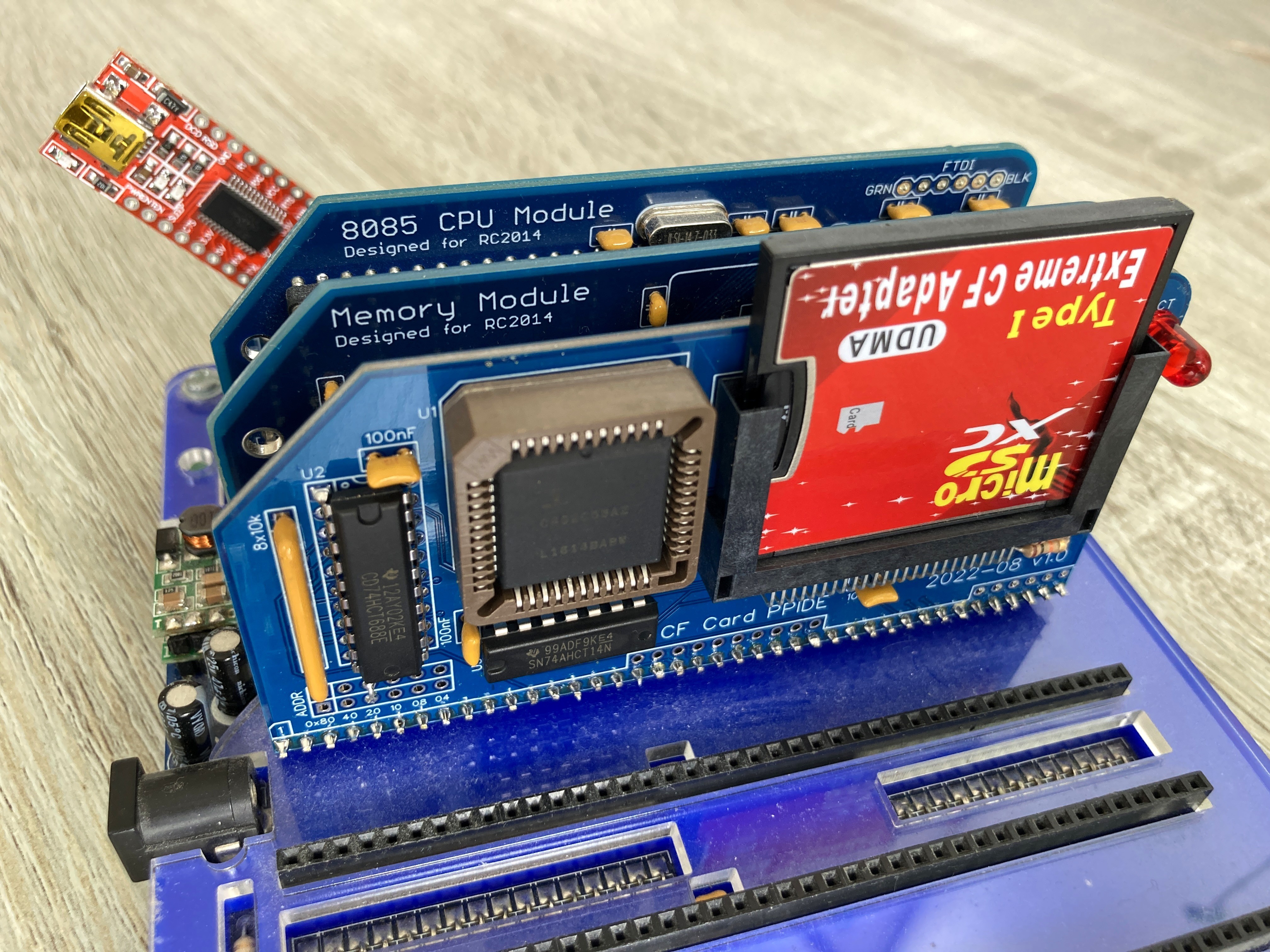
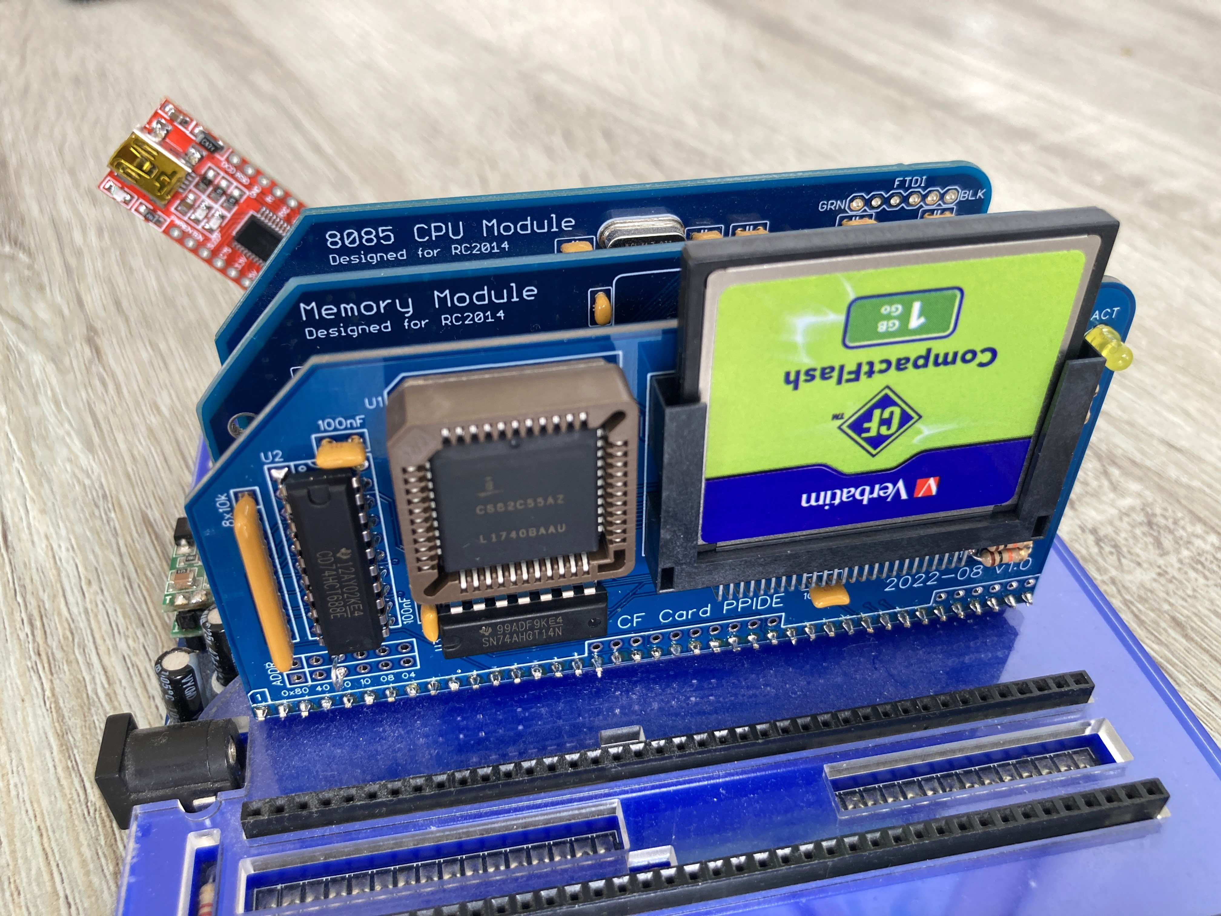
I'll have 2 or 3 PCBs spare (in AU/NZ area), so if someone wants one for postage plus A$10 (production cost) let me know.
Let me know by email of you'd like one or two PCBs (in blue) for postage plus A$10. I've a few spare now.
Phillip Stevens
Sep 23, 2022, 8:30:51 AM9/23/22
to RC2014-Z80
Phillip wrote:
My PCB order arrived, and I've built up a few of Dylan's CF Card PPIDE Modules. They look, and work, great!Both modern CF Cards and CF-SD Adapters are working for me.
I found when soldering the fine pitch connections of the through hole CF Card connector that (ONLY when soldering the adjacent GND connections) it was easy to create a solder bridge. Particularly pins 8 to 12, and 14 to 17. The heat travels quickly through the inner GND layer and the solder tends to track along the star connected TOP layer and make bridges with the molten solder.
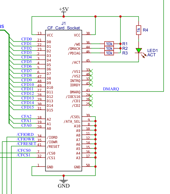
Of course this makes no difference to the functionality, but it does cause a bit of a "oh sh*t" moment before remembering the pins are already connected anyway.
Dylan has produced a new set of Gerbers (v1.1) that have separated the inner GND layer and removed the connects from the TOP layer. This should help prevent the GND Pin bridging.
I've attached them here, and they're also now attached to the CP/M-IDE v2.2 Release.
Thanks Dylan.
Cheers, Phillip
Tadeusz Pycio
Oct 23, 2022, 3:09:19 PM10/23/22
to RC2014-Z80
Today I had a moment to work on the CF interface and unfortunately it failed. I don't know where to look for a solution now, the time waveforms are in line with the CF specification and it's still wrong. Interesting that the newer cards behave better than the older ones, but it's hard to call it working correctly.
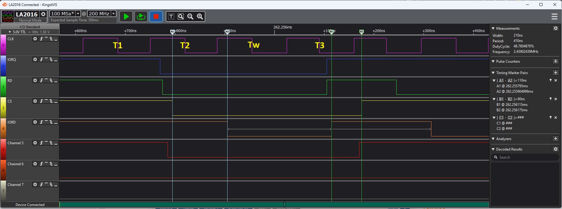
Tadeusz Pycio
Oct 24, 2022, 1:03:16 PM10/24/22
to RC2014-Z80
I think I have achieved full CF compatibility. Yesterday's failures were due to the fact that I made the mistake of generating the IOWR signal for CF by focusing my attention only on IORD. The time courses are compatible with the CF standard and I need time to build one more model to improve the IOWR.
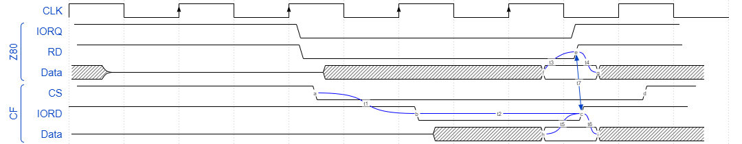
t1 ~ 110ns - min. 70ns (1)
t2 ~ 210ns - min. 165ns (1)
t3 = max. 60ns (2)
t4 = min. 0ns (2)
t5 ~ 60ns - min. 50ns (1)
t6 = 50ns (1)
t7 ~ 5ns
(1) - Timing CF True IDE in Mode 0
(2) - Z80 AC @ 8MHz
Tadeusz Pycio
Oct 24, 2022, 1:09:33 PM10/24/22
to RC2014-Z80
Wrong diagram :(
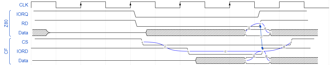
t5 = 50ns (1)
t8 ~ 60ns - min.20ns (1)
Tadeusz Pycio
Oct 25, 2022, 3:51:59 AM10/25/22
to RC2014-Z80
There is no such thing as a 'CF standard'. After meeting the required IOWR signal delays to CE, my PQI 128MB cards stopped working, the others work, along with the problematic SD to CF adapter. It's not a question of the timing of the IOWR signal to the CF 8-bit registers, as it's still wrong after changing the system clock to 3.68MHz. These cards work as the IOWR to CE delay is the propagation time of one gate (I will make a jumper). I'll get the PCB ready for production and check operation on the finished module. I wonder if there is any point in adding a 245 buffer.
Phillip Stevens
Oct 25, 2022, 8:22:54 AM10/25/22
to RC2014-Z80
Tadeusz wrote:
There is no such thing as a 'CF standard'.
I've got to guess that (except a few thousand retro-computer enthusiasts in the world) very few people are actually using the 8-bit XT fall back mode, so there's little incentive for manufacturers to properly implement and test that old mode. That might be the cause of the variability in functionality and standard support you're seeing.
Since the first version in 1995 the CF Standard has been constantly developing to support faster and faster 16-bit "True IDE" modes.
I read that it is likely that CF Revision 6.0 (supporting IDE Ultra DMA Mode 7) will be the last PATA version.
So Spencer's IDE Hard Drive Module will remain perfect for attaching CF Cards for as long as they're continuing to build CF Cards that support CF Standard Revision 6
Though, I'm sure we won't be pushing 167MB/s through them from a RC2014.
I've also been using Dylan's CF PPIDE Module now for nearly two months with both a CF Card and the SD Card in Adapter with zero issues.
So, it is not the cards that are the problem. Just saying, it might be trying to use them in a the 8-bit XT mode.
Cheers, Phillip
Tadeusz Pycio
Oct 25, 2022, 9:20:25 AM10/25/22
to RC2014-Z80
Hi Phillip,
As I mentioned before, the best solution is to use the CF PPIDE module, but I wanted to finish the work already started on the 8-bit module .... with the result shown here. I have retained full compatibility with PIO mode 0, my stubborn SD to CF adapter works, so there is some success. It is disappointing that manufacturers are lax about maintaining the standard. The next topic I want to tackle is reactivating GIDE for RC2014, as an IDE and as a dedicated CF module.

Alan Cox
Oct 25, 2022, 3:30:18 PM10/25/22
to rc201...@googlegroups.com
On Tue, 25 Oct 2022 at 13:22, Phillip Stevens <phillip...@gmail.com> wrote:
>
> Tadeusz wrote:
>>
>> There is no such thing as a 'CF standard'.
Yes there is, and a set of qualifying tests required to use the CF
>
> Tadeusz wrote:
>>
>> There is no such thing as a 'CF standard'.
logo and mark. So anything properly CF should meet it. Whether noname
made in China SD adapters do - shrug - .
> I've got to guess that (except a few thousand retro-computer enthusiasts in the world) very few people are actually using the 8-bit XT fall back mode, so there's little incentive for manufacturers to properly implement and test that old mode. That might be the cause of the variability in functionality and standard support you're seeing.
(it's actually ISA bus) and using the logo involves certification
which tests PIO 0 (indeed that is what all commands are issued using).
It sounds to me more like there are two ways of generating the timing
being used device side and something else is wrong that happens to
work one way or the other and thus the jumper works.
8bit mode is just a command and it has no timing implications.
PCMCIA mode uses PCMCIA timings which happen to basically be ISA bus as well.
> Since the first version in 1995 the CF Standard has been constantly developing to support faster and faster 16-bit "True IDE" modes.
> I read that it is likely that CF Revision 6.0 (supporting IDE Ultra DMA Mode 7) will be the last PATA version.
variant so they just have to make CF cards for a few years more to
meet rules in some countries on component supply after the ast product
release.
> So, it is not the cards that are the problem. Just saying, it might be trying to use them in a the 8-bit XT mode.
8bit mode too.
Alan
Tadeusz Pycio
Oct 25, 2022, 3:59:28 PM10/25/22
to RC2014-Z80
Another idea came to me. Since the IOWR satisfies with a small delay, maybe add another gate as an extension of it and also shorten the delay of the IORD appearance against the CS. This should already satisfy all CF cards and may not be the full PIO Mode 0 specification for CF, but it seems to work. I need to build another model.
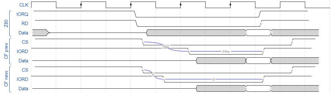
t1 ~ 50ns, t2 ~ 270ns
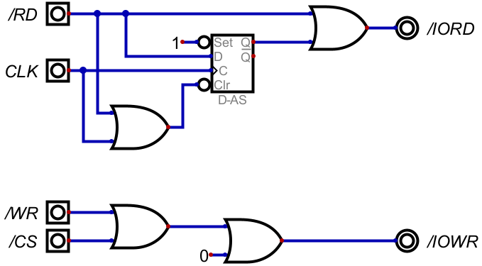
Tadeusz Pycio
Oct 26, 2022, 5:06:02 PM10/26/22
to RC2014-Z80
All the cards I have work, along with the adapter SD to CF. The /IORD delay shortening to /CS still meets the PIO Mode 0 standard (60ns), the /IOWR signal meets the CF PQI 128MB ;-), but all others work.
It was time for the PCB design.
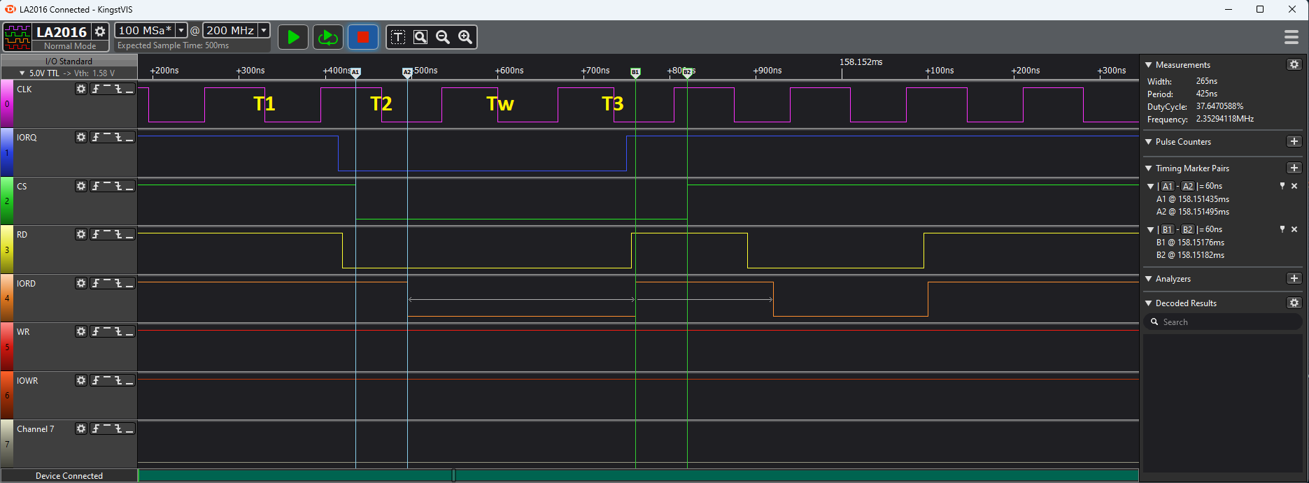
/IOWR delay with two gates.
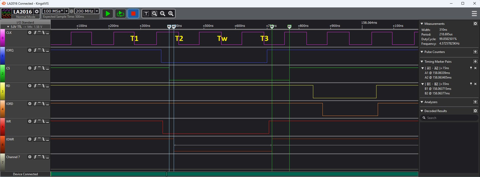
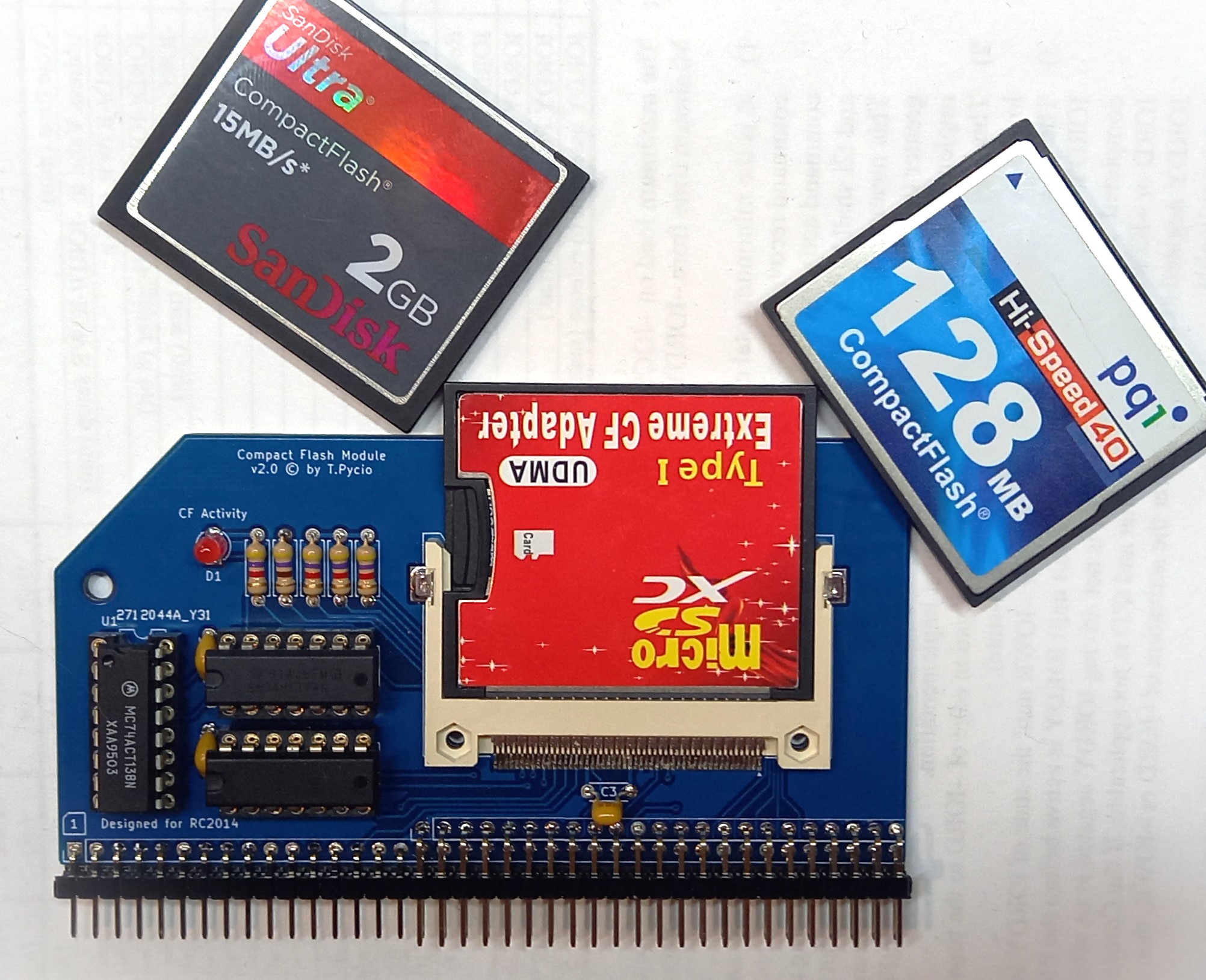
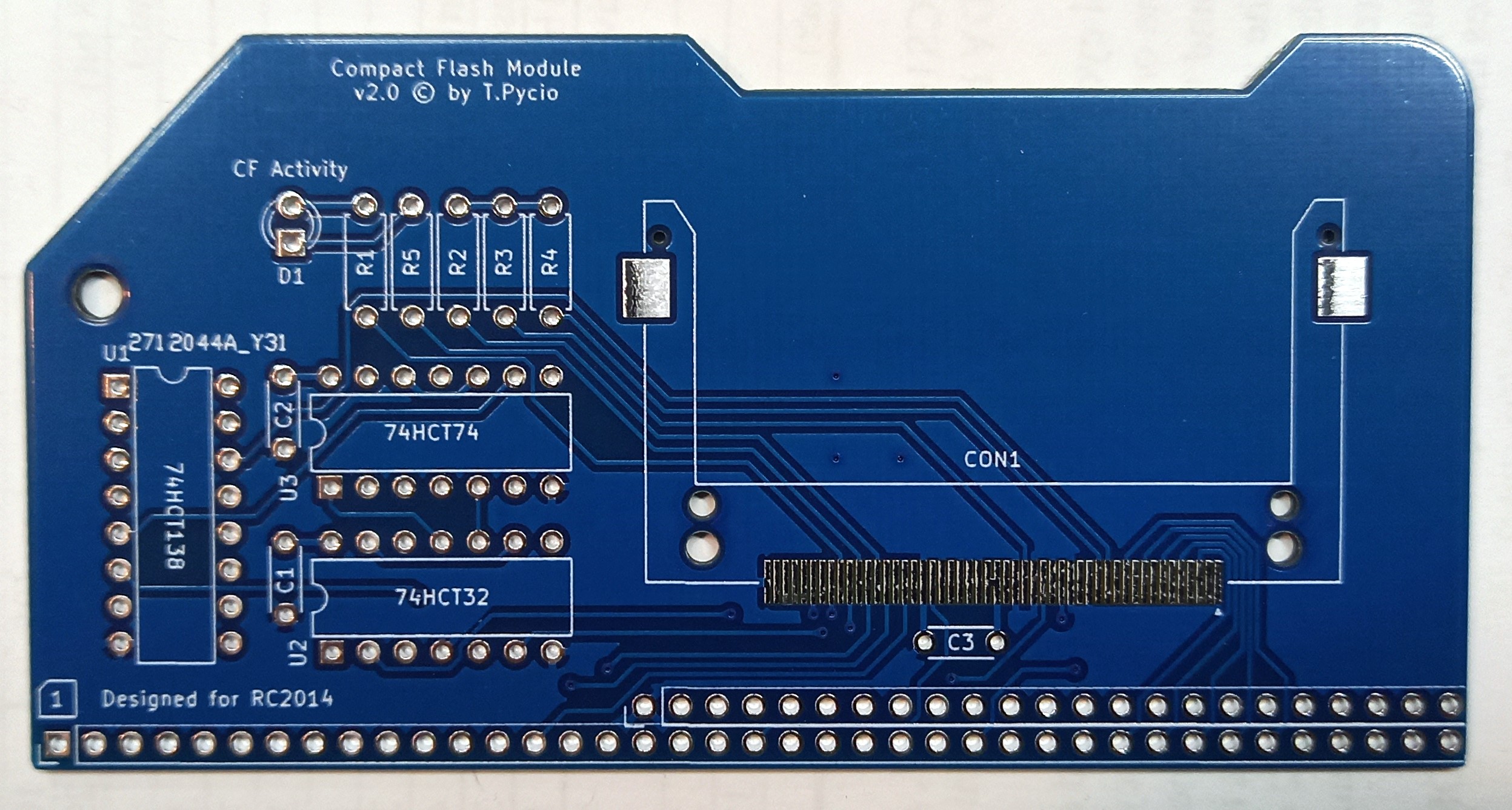
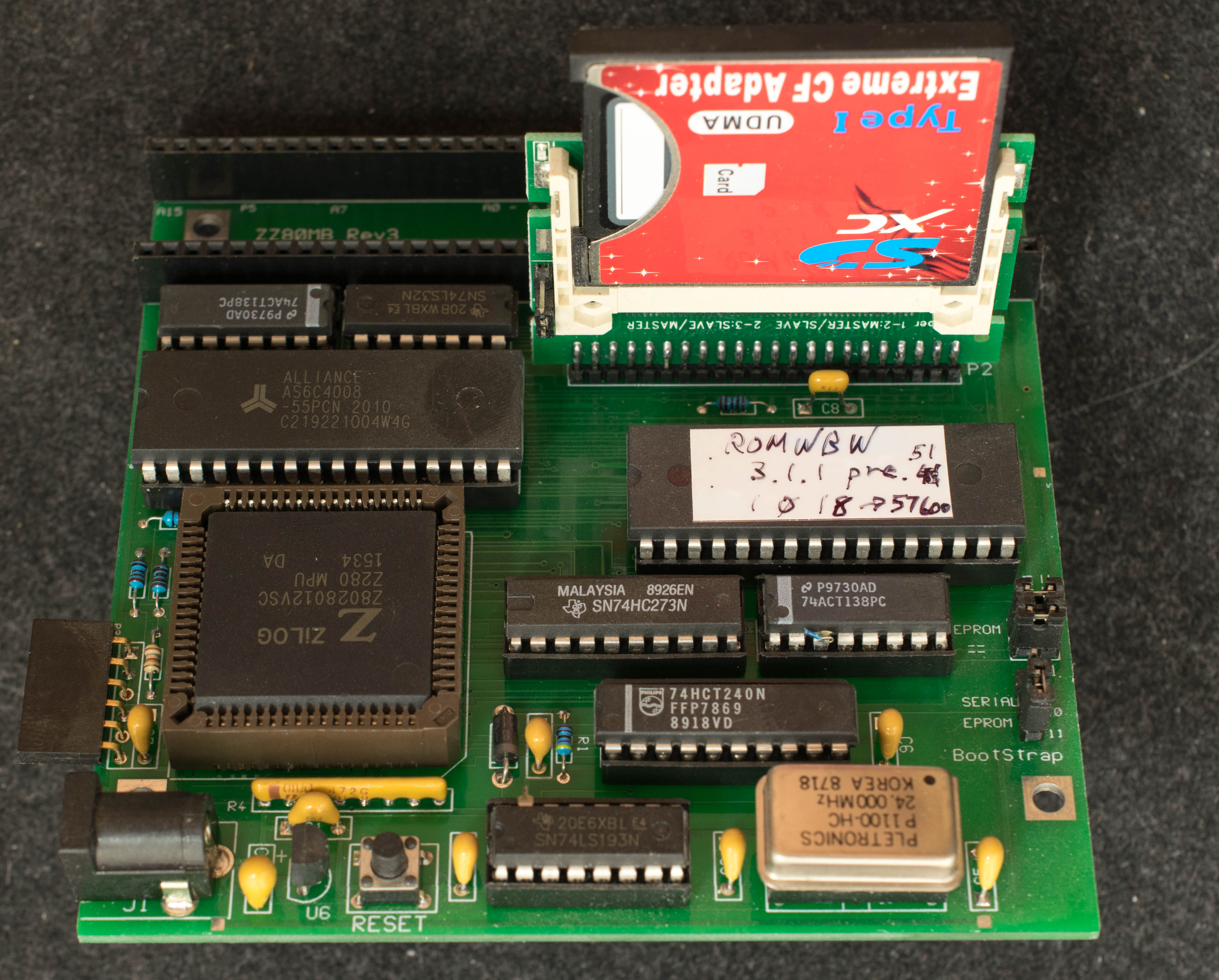
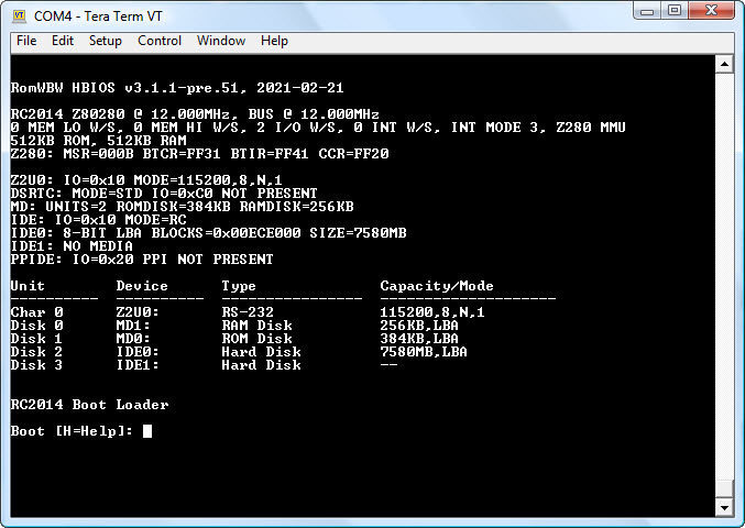
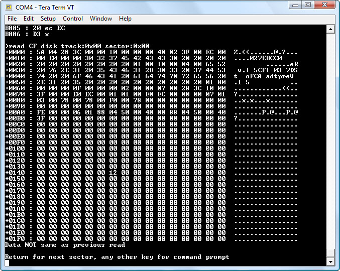
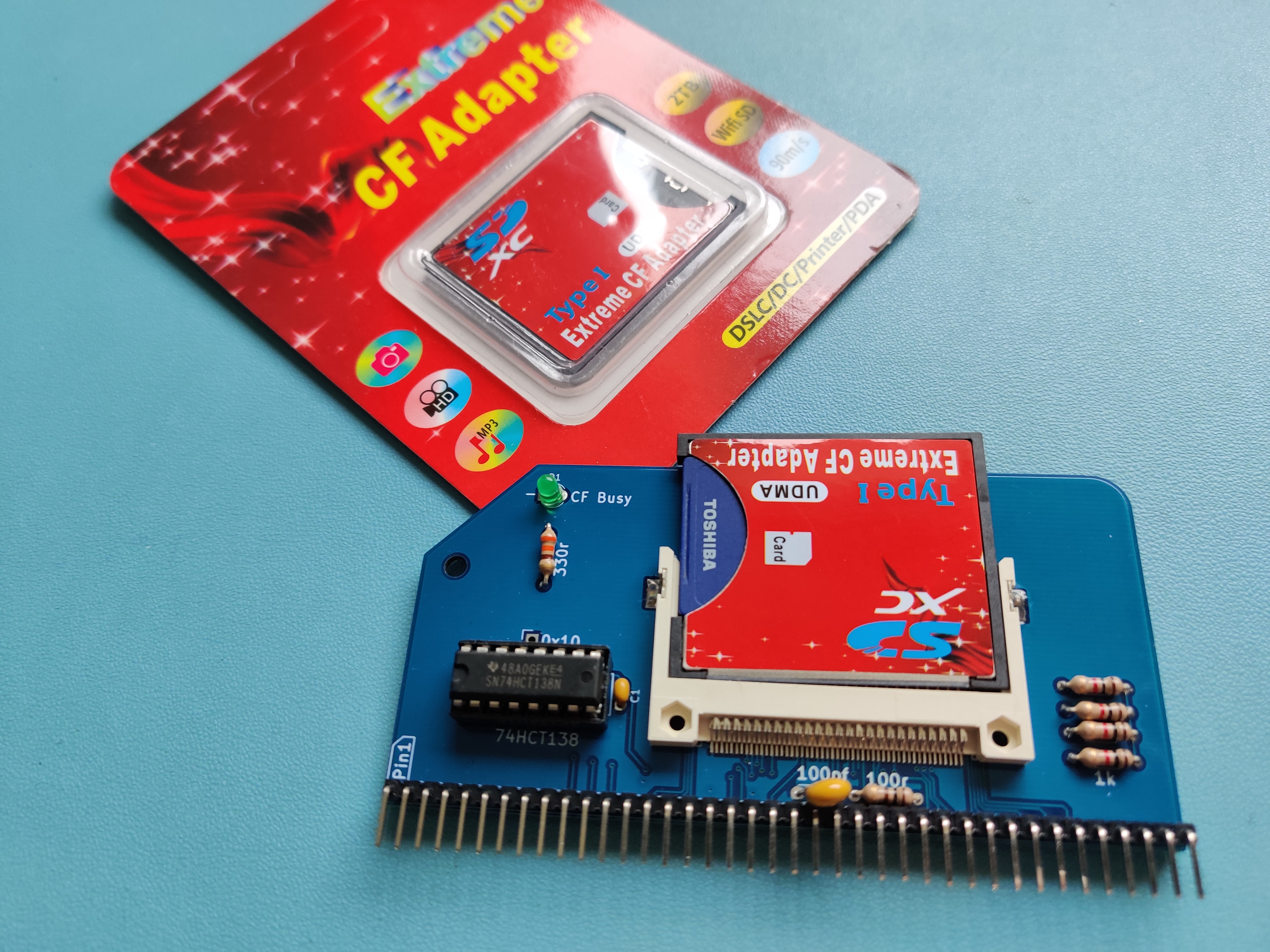
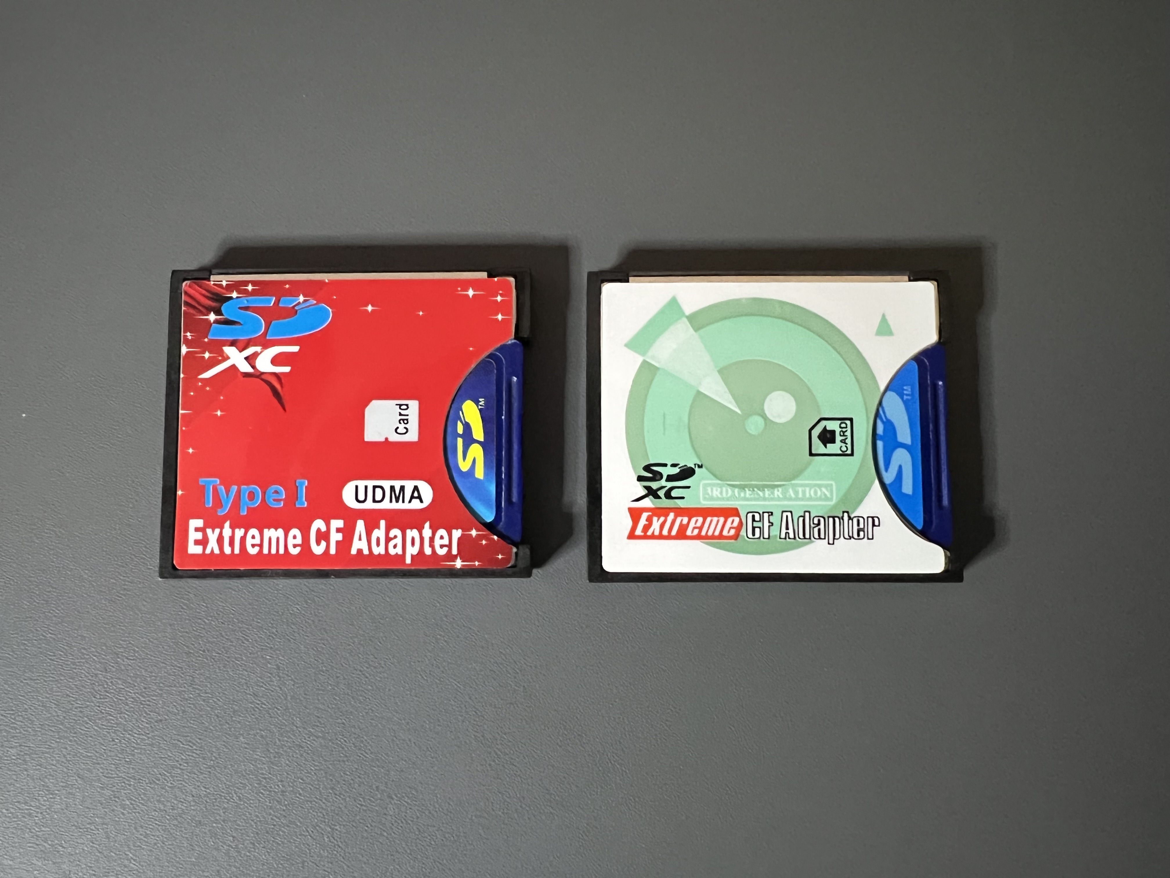
Phillip Stevens
Nov 10, 2022, 7:16:52 PM11/10/22
to RC2014-Z80
Tadeus wrote:
I have completed work on the CF interface. This was achieved without too much complexity. It works as expected, even with a troublesome SD to CF adapter and a SanDisk 2GB card that didn't work under either interface.
Tadeus, do you have some excess PCBs I could get or a parts / build list?
Perhaps it's time for me to play with CF 8-bit interfaces.
Cheers, Phillip
Tadeusz Pycio
Nov 10, 2022, 7:47:36 PM11/10/22
to RC2014-Z80
Hi Phillip,
I'm afraid shipping from Poland to Australia will be more expensive than ordering these PCBs from a Chinese factory. I'm making the Gerber files available here for non-commercial use, it's probably a more reasonable solution.
Phillip Stevens
Nov 10, 2022, 9:50:48 PM11/10/22
to RC2014-Z80
Tadeusz wrote:
I'm afraid shipping from Poland to Australia will be more expensive than ordering these PCBs from a Chinese factory. I'm making the Gerber files available here for non-commercial use, it's probably a more reasonable solution.
Ok. I've ordered a few PCBs and if anyone in the Australian/NZ postal "singularity" wants one, just send me a direct message or email.
There are 5x remaining as I type, each A$5 plus AusPost mailer bag.
Cheers, Phillip
Tadeusz Pycio
Nov 11, 2022, 4:25:00 AM11/11/22
to RC2014-Z80
The most important piece of information is missing here - the CF connector is exactly as used in the official CF module - Attend 101D-TAA-R01. It is available at major electronics shops, I bought mine at tme.eu. The other components are typical and follow from the schematic. The only deviation I used in my model is the use of a 1uF capacitor C3 at the CF supply.
Phillip Stevens
Nov 11, 2022, 5:32:39 AM11/11/22
to RC2014-Z80
Tadeusz wrote:
The most important piece of information is missing here - the CF connector is exactly as used in the official CF module - Attend 101D-TAA-R01. It is available at major electronics shops, I bought mine at tme.eu.
I can see it at TME (in Europe), but I can't see any products from Attend on Mouser or DigiKey (USA or Australia).
Does anyone know what an equivalent product part number is, available either of those two platforms (Mouser or Digikey)?
P.
It is loading more messages.
0 new messages