Help needed

charu...@gmail.com
hello friends,
I am stuck with my project at the point seen in the video attached herewith
These are my details -
1. I used the latest Raspbian OS available on the Raspberry.org site.
2. My PCB build is beta4
3. My Pi is v4 with 4Gb
4. I compiled the dev version following https://github.com/pa3gsb/Radioberry-2.x/tree/master/SBC/rpi-4/device_driver/driver
5. My firmware is getting registered with my MAC address on the site, don't know if that makes sense here.
6. Able to load/install pihpsdr without CW option and no errors.
Please help
de vu2upx (Charudatt)

taka sugi
I experienced the same problem.
Please check below…
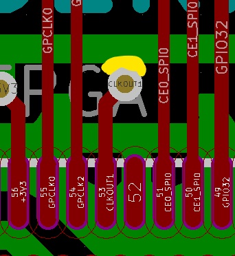
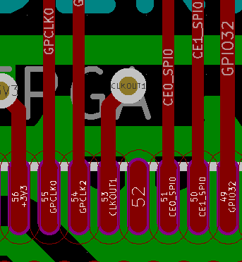
1. If pin53,69 connection line is connected to +3.3V line, check the FPGA
pin53 VIA(through hole) and pin 47,56,62(+3.3V) by a tester,
note: pin53-69 is connected by inner/Cu1 layer
2. Check the waveform of pin53/69 clock input. If strange, then clock line
is shorted to 3.3V line.
3. My PCB(JLCPCB), pin53-69 line was shorted to +3.3V line!
and I repaired, RB works well!
I think the shortage reason is that JCLPCB design rule “VIA pad to track”
minimum clearance: 0.2mm does not satisfy. I check the PCB file by KiCAD,
the clearance between pin53 VIA and +3.3V line is only 2.5mil( 0.0635mm)!
Please refer to attached file about the detal.
DE JA1TLH/Taka

Radioberry
charu...@gmail.com
I confirm that Pin#53/69 are shorted to 3v3 on a blank PCB made from JLCPCB.
Continuity check
regards
charudatt – VU2UPX
From: Radioberry <radio...@googlegroups.com>
Sent: 16 April 2021 12:20
To: Radioberry <radio...@googlegroups.com>
Subject: Re: Help needed
Hi Chara and Taka,
Looked into your mp4. Pihpsdr is displaying 0.0 as gateware version in the top.
The gateware version is collected via SPI commands.
There are mainly 2 reasons why you are getting these 0.0 (maybe occuring from different situations)
- the gateware is not loaded (check the logging if the driver is loading the gateware)
- you are missing the ad9866 clock at pin 53.
The SPI interface is initialized (HDL fragment from gateware: spi_slave spi_slave_inst(.rstb(!reset)......)
The clock controls the reset flag... and so the initialization of the SPI interface in the gateware.
in your case it seems that the clock is not there.
In https://github.com/pa3gsb/Radioberry-2.x/wiki/Radioberry---Configurations some guidance is present to check your setup.
Nice you installed the software by the manual instruction.
An easy way is to use the release and run a script:
Hardware issue
If the clock is attached to the 3V3 ; the clock is not there and indeed you are facing the same situation.
Quite recently is got a private mail from Manfred DB2OJ reporting this.
I thought he also used PCB from JCLPCB.....not sure if the problem occurs for others PCB fabs?
At the bottom side check the via (clkout1) ; i think you can fix the issue there.

--
You received this message because you are subscribed to the Google Groups "Radioberry" group.
To unsubscribe from this group and stop receiving emails from it, send an email to radioberry+...@googlegroups.com.
To view this discussion on the web visit https://groups.google.com/d/msgid/radioberry/9600b3aa-b441-4911-b1fe-c452434f4a4fn%40googlegroups.com.

Manfred Brederlow
Hello everybody,