New OpenPNP ReferencePushPullFeeder class

ma...@makr.zone

Bill Ruckman
--
You received this message because you are subscribed to the Google Groups "OpenPnP" group.
To unsubscribe from this group and stop receiving emails from it, send an email to openpnp+u...@googlegroups.com.
To view this discussion on the web visit https://groups.google.com/d/msgid/openpnp/b327fc09-7ca2-4257-9744-bca56928b373%40googlegroups.com.
ma...@makr.zone
- Use case: prototyping/very small runs.
- All 3D-printed, no hardware (screws, springs etc.) required.
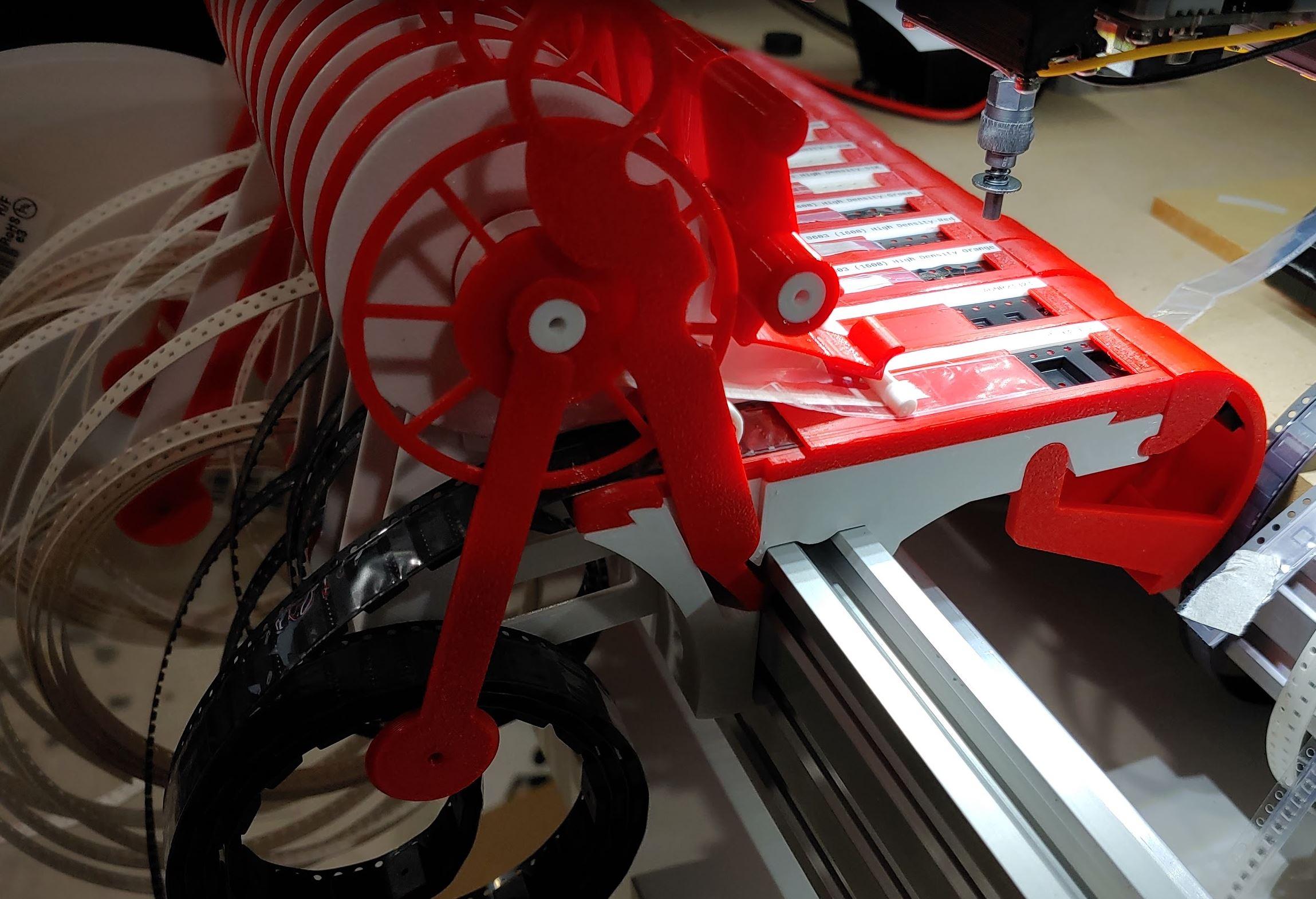
- Complete solution: reel holder, feeder mount, cover tape spool, spent tape chute.
- Supports 2mm pitch/0402 parts, i.e. it can feed two parts per tape advancement.
- Simple and no-fiddle tape and reel loading, including cover tape spool clamp.
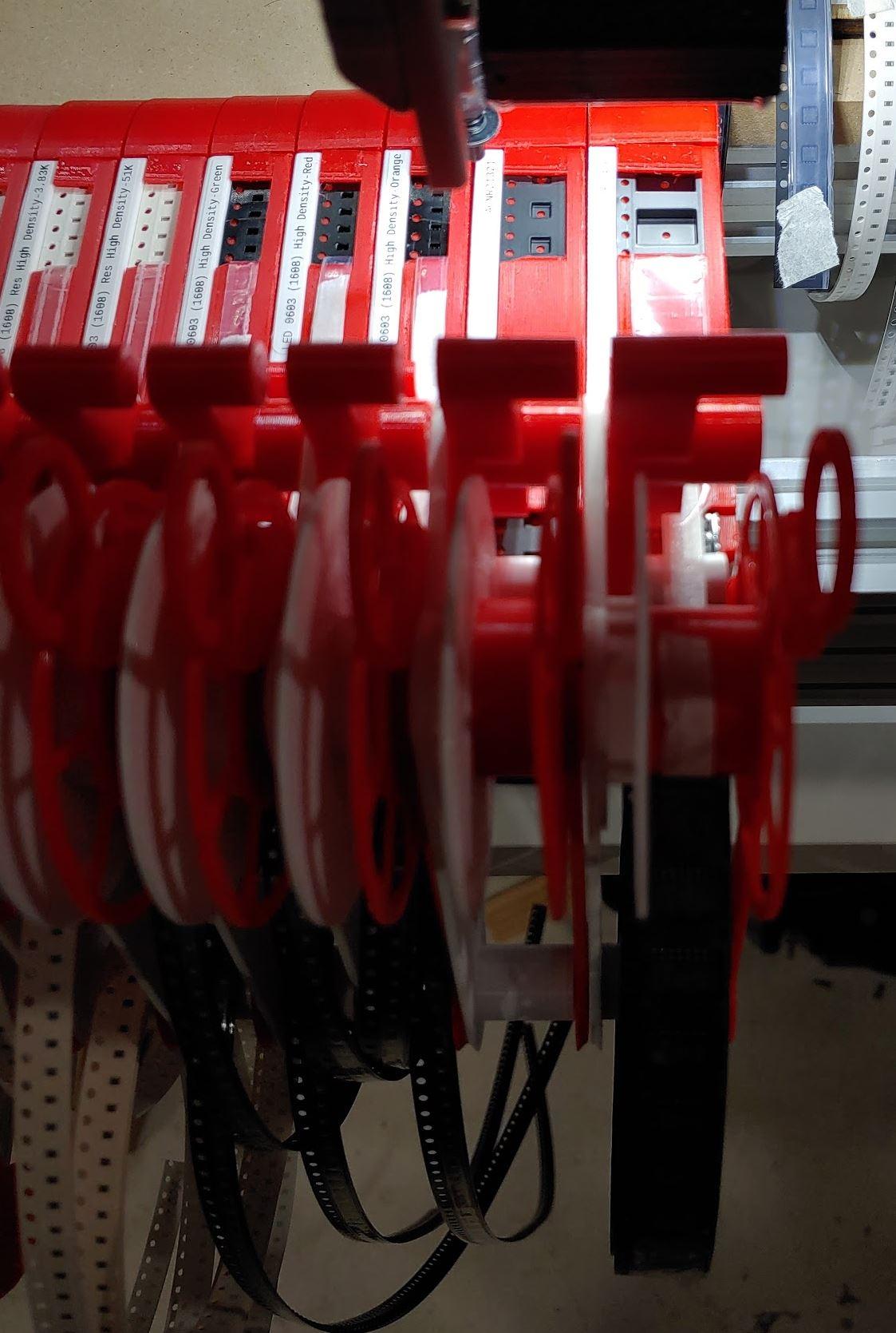
- Feeder can be mounted between two mounted feeders, no tools, no side access required.
- Relatively fast print: ~3.5h (or less) for complete feeder.
- Low cost: $2 per feeder (PETG filament).
- So cheap, you can store all your reels in the feeder until empty (if ever). Cartridge style.
- All parts can be replaced, has punch-out holes to remove parts without breaking them.
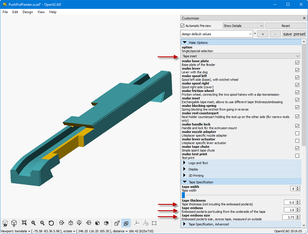
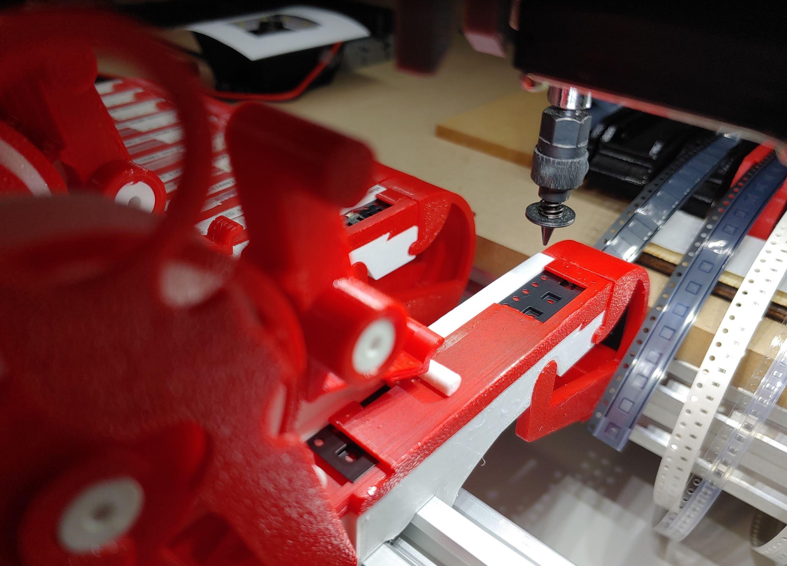
- The tape inset (see where the tape is inserted in the animation) is all you need to exchange for use with different tapes (paper thickness, embossed pocket width and depth, etc.). Provides snug fit for low vibrations and high precision pick location repeatability.
- Insanely parametric OpenSCAD solution with Customizer parameter user interface, extensive comments in the code.
- Open Source Hardware, GPL license.
Watch the movie:
More info and source code:

bert shivaan
--
You received this message because you are subscribed to the Google Groups "OpenPnP" group.
To unsubscribe from this group and stop receiving emails from it, send an email to openpnp+u...@googlegroups.com.
To view this discussion on the web visit https://groups.google.com/d/msgid/openpnp/bfd39d02-fb24-422b-802f-60e41128405d%40googlegroups.com.
bert shivaan
ma...@makr.zone
Now if we just had a good solution for 0402 cut tape
Have you tried my BlindsFeeder?
https://youtu.be/dGde59Iv6eY?t=366
https://makr.zone/new-openpnp-blindsfeeder/353/
_Mark

Balázs buglyó
--
You received this message because you are subscribed to the Google Groups "OpenPnP" group.
To unsubscribe from this group and stop receiving emails from it, send an email to openpnp+u...@googlegroups.com.
To view this discussion on the web visit https://groups.google.com/d/msgid/openpnp/ab02dfe0-8ef3-bb06-4ca8-3ef00792ebb7%40makr.zone.

Marek T.
ma...@makr.zone
> Ps: are these feeder options are custom made or built is 2.0 i did not use it yet.
The BlindsFeeder and the ReferencePushPullFeeder (software side)
are only available in OpenPNP 2.0. And the ReferencePushPullFeeder
is still just a Pull Request, it must first be reviewed before it
can be merged into OpenPNP 2.0. You can build it from my repo,
though:
https://github.com/markmaker/openpnp/tree/feature/reference-push_pull-feeder
_Mark
ma...@makr.zone
The width may be modified, parametrized. What with the height, higher parts like electrolitic capacitors etc? Feeder looks like only for flat tapes destined for, or maybe I've taken a look wrong, isn't it?
Hi Marek
The feeder has what I call a "tape inset", a small part that you
can very quickly print to adapt different tapes to the feeder. You
can parametrize it for thickness, and embossed pocket depth and
size. If you watch closely, you can see, I use one with clear
plastic embossed carrier tape in the video here:
https://youtu.be/5QcJ2ziIJ14?t=467
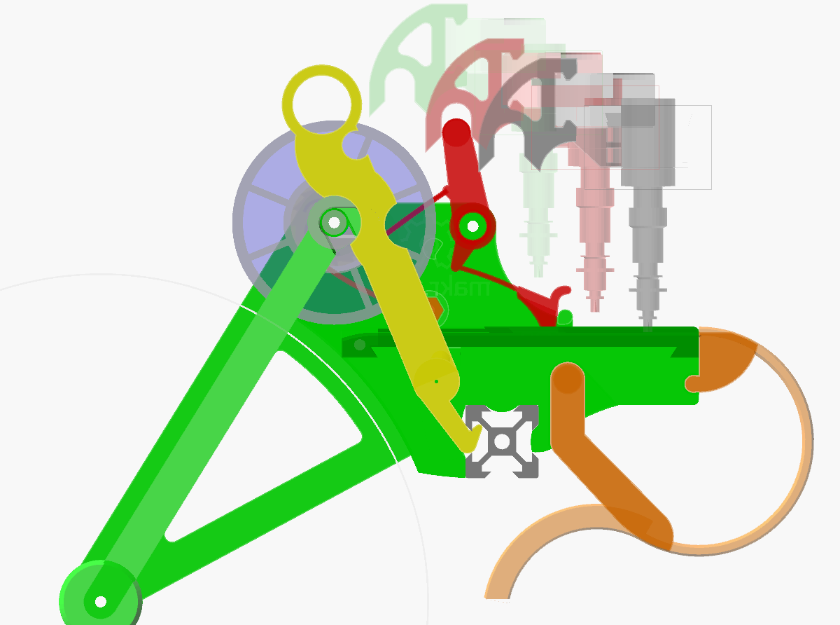
This is how you can parametrize it, and in the assembly animation
GIF you see how the inset is snapped into the feeder:
https://makr.zone/wp-content/uploads/2020/04/PushPullFeeder_Assembly.gif
_Mark
bert shivaan
--
You received this message because you are subscribed to the Google Groups "OpenPnP" group.
To unsubscribe from this group and stop receiving emails from it, send an email to openpnp+u...@googlegroups.com.
To view this discussion on the web visit https://groups.google.com/d/msgid/openpnp/e94984ec-1f8f-478d-10a7-050000f0c631%40makr.zone.
ma...@makr.zone
> I thought I had read something about it having problems with 0402?
No, it was specifically developed to support 0402! That's the
principal package I want to use in my projects.
I was just frank in my description that it requires some
3D print tuning and careful handling when loading the tape.
But this was more to say, that 0603 handling is child's play! :-)
0402 parts are 1.5 times smaller than 0603, but this means that
in 3 dimension they are 1.5 to the 3rd power less heavy, i.e.
3.375 times lighter, and assuming that the lift (vibration
amplitude) required to topple them over their edge is also 1.5
times lower, this means that the potential
energy required is weight x lift = 1.5 to the 4th power,
i.e. 5 times lower with 0402 as compared to 0603. That explains a
lot!
Watch the movie, where I made a point of using 0402. It works!
I would be very interested in your experience with it!
_Mark
Marek T.
bert shivaan
--
You received this message because you are subscribed to the Google Groups "OpenPnP" group.
To unsubscribe from this group and stop receiving emails from it, send an email to openpnp+u...@googlegroups.com.
To view this discussion on the web visit https://groups.google.com/d/msgid/openpnp/35b78ab0-128c-8448-4486-d60941fd67cc%40makr.zone.
Marek T.
But the main disadvantage (in my personal opinion) is that this feeder requires additional horizontal move and then pick. I'd like to see this doing advancement with the only one vertical move the same that's doing picking - like old Yamaha. It means if z to Pick is -10mm, an advanced is made on the way between 0-5.
Of course I mean to avoid of time loose. But looking on fact that not many people here care about the speed, I'm probably one of the few who won't like it :-).
Marek T.
ma...@makr.zone
Hi Marek
This is really for the DIY/prototyping audience. Your
fast machines, your professional volume production are really not
what I was thinking about ... but you knew that, right? ;-)
> doing advancement with the only one vertical move the same that's doing picking
Same move as picking is not working with 0402! You need a
way to skip the feed for the second part, unless you find a way to
do a reliable "half sprocket" advance. I assume most enthusiasts
will try to go 0402 these days, so this is relevant and a simple
mechanical DIY 0402 feeder is AFAIK missing.
But yes, of course this is not a fast feeder. It
trades some speed for the goal to work without springs and without
additional electronics. However, I tried hard to make the required
moves as short and direct as possible. The leg speeds you see in
the video are also not yet optimized.
The new feeder aims to be cheap so I can have a lot of them and
I will never need to unload/reload tapes! Even with pro
feeders, this seems to
be quite complicated, time consuming and if you're
unloading/loading a partially used reel, it seems this would be
wasting an absolutely astonishing amount of parts, unless you can
somehow make sure you can untangle the spent tape and cover tape
back out of these long channels in the feeder both intact and in
sufficient length, so they can become the leaders when you later
reload the reel.
I'm also assuming and hoping this feeder will evolve with the community and it is not worth designing it for eternal life, but rather continually replace the worn-out ones with better versions.
Currently I have one part that I need in relatively large
quantities (bypass caps). If the new feeder proves inadequate for
such parts, I can still attach one or two professional feeders.
Between these and the cut strip feeders, this new feeder fills
an important niche, I believe.
What do you think? :-D
_Mark
Marek T.
I like an idea to have hundreds of feeders costing less than reel with parts on it and don't need to change them :-).
bert shivaan
--
You received this message because you are subscribed to the Google Groups "OpenPnP" group.
To unsubscribe from this group and stop receiving emails from it, send an email to openpnp+u...@googlegroups.com.
To view this discussion on the web visit https://groups.google.com/d/msgid/openpnp/7cbd59c5-201a-acd6-9435-2907297effca%40makr.zone.
bert shivaan
ma...@makr.zone
The built-in pipeline will work with orange-to-green high
saturation colors:

But any color different from the tape can be made to work by
tweaking the pipeline. The color is much less important than with
the BlindsFeeder, because the parts are not inside the sprocket
holes (hopefully ;-). Still I assume a high saturation color is
better, because it works amazingly independent from brightness, so
the shadows inside the holes are no problem, even if asymmetric. I
you have it, use green, as I believe it is the accepted "green
screen" color in electronics (Juki nozzle tips).
Note also, you only need to print the "Tape Inset" with that
color, the other parts are irrelevant.
Be sure to use PETG or another springy and tough material.
_Mark
To view this discussion on the web visit https://groups.google.com/d/msgid/openpnp/CA%2BKNHNxrTjz88z_tYmUuespnRmvS-H25n4C1xUYz9sW9fWM2aA%40mail.gmail.com.
bert shivaan
To view this discussion on the web visit https://groups.google.com/d/msgid/openpnp/7ef020ef-36b6-5dc4-5194-0d8a07b2c295%40makr.zone.

Hanski
ma...@makr.zone
Hi Hanski
Thanks!
It is a very good thing to learn how to build OpenPNP, if you are
a coder in some way or other. So if this is the opportunity, go
for it! It's liberating.
If you are not a coder, I would wait. I have one test to do (job)
and then Jason is usually quite fast in merging new stuff in, if
it doesn't change existing code too much. If there is an
unexpected snag in my PR, you can always reconsider later.
_Mark
--
You received this message because you are subscribed to the Google Groups "OpenPnP" group.
To unsubscribe from this group and stop receiving emails from it, send an email to openpnp+u...@googlegroups.com.
To view this discussion on the web visit https://groups.google.com/d/msgid/openpnp/4ae3c019-cd8f-4aef-bbf8-b3e5dc74dca5%40googlegroups.com.
Hanski
You received this message because you are subscribed to a topic in the Google Groups "OpenPnP" group.
To unsubscribe from this topic, visit https://groups.google.com/d/topic/openpnp/VDEKlvYKfTY/unsubscribe.
To unsubscribe from this group and all its topics, send an email to openpnp+u...@googlegroups.com.
To view this discussion on the web visit https://groups.google.com/d/msgid/openpnp/34031794-cce9-661b-c125-ecc35d870bd3%40makr.zone.

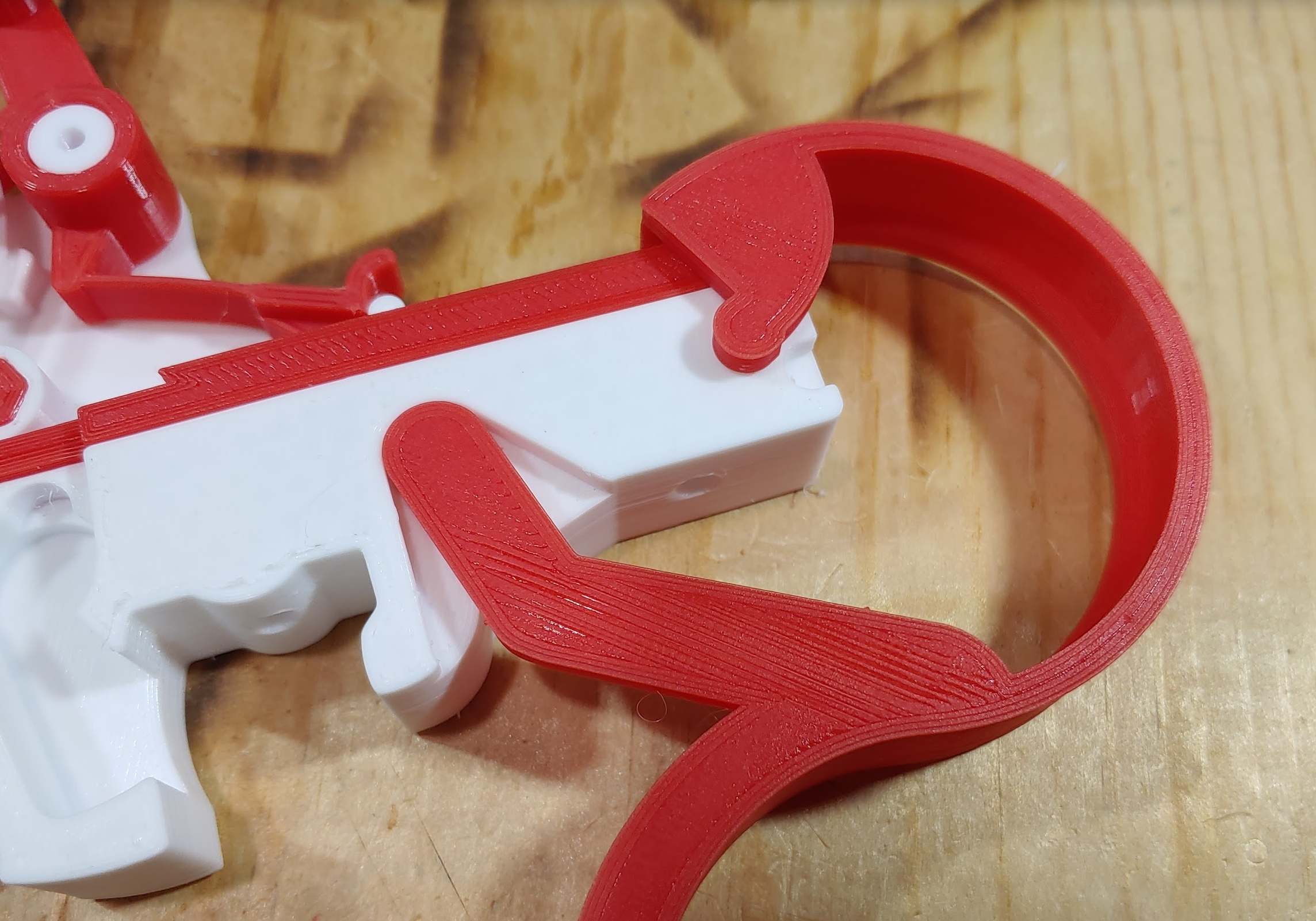
Jed Smith
I like your latching mechanism. Have found putting a screw down below where the tape advances over is a pain. You have to cut the tape and retract it a little to pull the feeder out.
ma...@makr.zone
Hi Jed
> I'm impressed with the design Mark, really well thought out.
It's evolved from yours, so thank you twice ;-)
> It looks like your design sits up pretty high.
There were several considerations:
- Full feeder must absolutely print in one go (PRUSA i3 and
similar standard print volume).
- Still want this to be a complete solution, reel holder and
spent tape chute included, so everything must be quite compact.
- The Feeder should also be as small as possible when assembled
(for storage with the reel).
- With the Liteplacer camera being at +Y ~30mm the nozzle tip
needs to be able to move 30mm over the pick location.
- Assuming the feeders form a row, I cannot sidestep the feeder
(though the lever actuator is designed to go between
two levers when picking).
- So I had to clear the front of the feeder and the solution was
to reach over it for the lever.
- It is designed to be at the table/machine reach edge, so the
height actually does not matter (as far as I see).
- Wanted it to work with a low as possible Safe Z, because the
Liteplacer Z is relatively slow, so lowering Safe Z down helps.
- So the lever actuator should not reach lower than the other
structures on the Nozzle to add no new collision constraints for
Safe Z for all the various machines out there (on the Liteplacer
the nozzle rotation stepper body forms the natural
limit/underside).
- So this gives you the minimal height of the lever knob.
- The spool then just uses the available height.
- Note that the extrusion should be mounted just beyond the
table edge (assuming the Liteplacer front legs as edge) and -20mm
down. So the pick location is at proper PCB/table surface
level.
_Mark
--
You received this message because you are subscribed to the Google Groups "OpenPnP" group.
To unsubscribe from this group and stop receiving emails from it, send an email to openpnp+u...@googlegroups.com.
To view this discussion on the web visit https://groups.google.com/d/msgid/openpnp/a5912d95-e307-418e-8e2f-b0e557f3ea15%40googlegroups.com.

Pekka Roivainen
I had to modify it quite a lot, mainly as my camera is about 60mm from the nozzles instead of your 30mm, so I had to move the lever mechanism back a lot. I also wanted the pick height to be 16mm above the extrusion instead of the default 20mm to match with my other feeders. For that, I needed to reduce the size of the locking mechanism, which was the only time I had to touch the code by the way as that was not parametric if I understand correctly. The lock still works and mounts the feeder in place so firmly! Lot of tweaking on all other parts as well, my DIY printer is quite sloppy, so let's see if it holds the tolerances when I try to print more. For axle fit I used a reamer to get the fit really good. Next I of course need to design the actuator and see if it works with that..
On Saturday, April 11, 2020 at 12:14:28 AM UTC+3, ma...@makr.zone wrote:
Hifor those interested, I made a new feeder class PR:Watch the movie:With OCR part recognition, one-click setup and other cool features:_Mark
ma...@makr.zone
Thanks, and wow are you quick in adapting this so far!
:-)
_Mark
--
You received this message because you are subscribed to the Google Groups "OpenPnP" group.
To unsubscribe from this group and stop receiving emails from it, send an email to openpnp+u...@googlegroups.com.
To view this discussion on the web visit https://groups.google.com/d/msgid/openpnp/7bb83bf5-4365-42a7-9b34-d2c563b256e7%40googlegroups.com.

Peter Chaisty
ma...@makr.zone
Hi Peter
theoretically other extrusions should work too, the extrusion is also parametric.
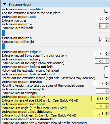
But I may have made some assumptions in the lock design, that
won't work, like the angle of the slot.
OpenBuilds is a widely available Open Source Hardware product, so
I believe you should get adequate supply everywhere and I'm sure
any rip-offs and clones will work too.
https://openbuildspartstore.com/v-slot-linear-rail-1/
This is just the first UK shop I found:
https://ooznest.co.uk/product-category/parts/mechanical-parts/v-slot-extrusions/
You can use 20x20mm V-Slot extrusion...
https://ooznest.co.uk/product/clearance-v-slot-linear-rail-20x20mm/
... or other dimesions if you're prepared to tweak the model
params.
_Mark
Peter Chaisty

Melitonas
ma...@makr.zone
Hi Melitonas
My gut feeling is that you must solve this problem with your
printer rather than trying to mend it in the model. Are you
printing in PETG? I'm just asking because I hat an awful
experience with ABS. ABS didn't work at all.
If you have problems with PETG please try using a adhesive Spray.
It works wonders!
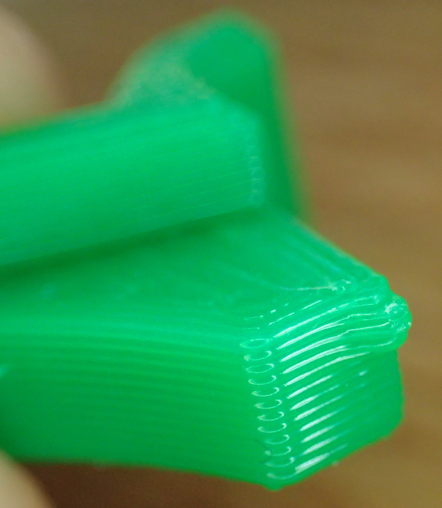
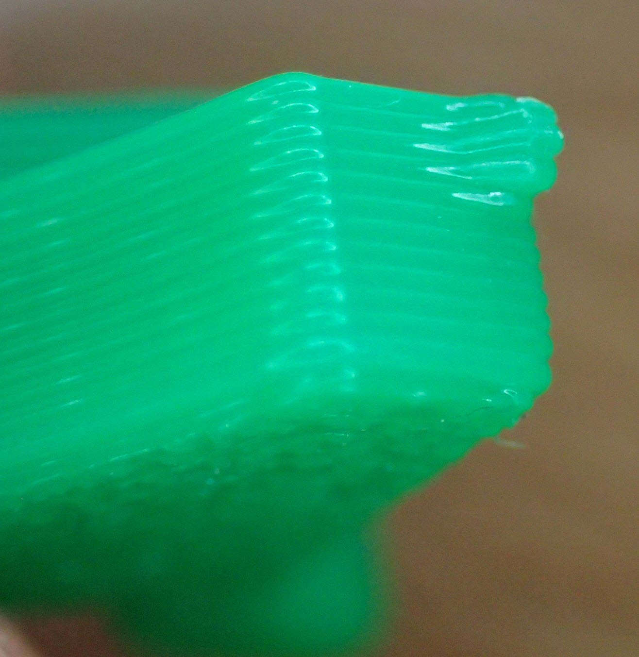
Also I don't really understand your question. The bevel will
normally help against warp and not worsen it.
Having said all that, you can change how the model will be beveled.
First there is the bevel_z variable. It controls most large bevels. It is set to two layer height by default. Change it as you like.

And then there is the default parameter value for bevel in beveled_extrude().
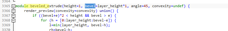
It is set to one layer height by default. Change it as you like.
_Mark
--
You received this message because you are subscribed to the Google Groups "OpenPnP" group.
To unsubscribe from this group and stop receiving emails from it, send an email to openpnp+u...@googlegroups.com.
To view this discussion on the web visit https://groups.google.com/d/msgid/openpnp/6321c8a0-a633-4c6d-967c-5662d00e585a%40googlegroups.com.

Scott Wilson

Keith Hargrove
Melitonas
I am using noname PLA. Just ordered original PETG from Prusa.
Will try different slicer settings and will try to remove the bevel :) until the PETG arrives.
Do you use adhesive Spray on the Powder Coated original Prusa heatbed? What brand of Spray?
To view this discussion on the web visit https://groups.google.com/d/msgid/openpnp/b1c2da89-8b2e-e090-3f89-babbfbf604e0%40makr.zone.
ma...@makr.zone
Cool.
> Do you use adhesive Spray on the Powder Coated original Prusa heatbed? What brand of Spray?
Yes. I'm using "3DLAC":
https://www.3dlac.com/3dlac/3dlac-product/
This is just the first brand I tried, so no comparison.
For a fresh session I use Isopropanol to clean first. Then for
two, three prints I only spray. Then I wash using warm water and
use Isopropanol again.
If the bed is cold I spray until it looks slightly wet which is
quite a lot. If it's warm this won't be a good indicator (dries
quickly), so use your "timing" from the cold sprays.
If you have the PRUSA, take the sheet away from the printer to
spray. I didn't do that first and it caked the rails. But it can
be cleaned easily and relubricated with the lube coming with the
PRUSA.
_Mark
To view this discussion on the web visit https://groups.google.com/d/msgid/openpnp/CAO32xPpapSVkFimYQnBC%3DagpGABXNp9mcyJhDtgjyJS9wrGqyw%40mail.gmail.com.

eSlavko
As I already tryed similar concept with slip clutch I know that there are big chances to fail. It will be to tight or to lose. That should be improved. In my printer I just can't get right tension. Maybe magnetic slip clutch can be made in near same space (Mike idea)
Drilling for tape drive pin is hard job to do correctly. The place where drilling start the flank should be perpendicticular to the dril to have "clue" on what direction to drill. Even preprinted hole should help guiding while drilling.
To drive the unit insane force is required. After printing I postdrilled all holes to have just little sloop. But still really high force is needed. Come little better when I grease sliding parts but still I think the force is to high. Even from engineering side of view is bad idea to have same sliding material in both elements. I think at least there should sacrifise "all part printed - no vitamins" and add some steel rood for axes. Somewhere I see that betwen two plastic parts are just bigger gap with piece of brass tube inserted as plain bearing.
Don't know how long the ratchet spring will do the job. PLA will probably snap fast. PETG should be better. As the idea we allready (probably) have a lot of good material for leaf springs. FR4 is "insane" good material for that and that's nice area for reciclyng bad designed boards. With proper design just flat rectangles are needed.
Same apply for spring that drive tape. Actually there are design flaw as the most bending area has sharp corner.
For the final one question.
What is the drive scenario?
I assume Pull to move ratchet to new hole in tape, and then push to advance tape. Or the spring should return to final location?
If machine need to return to exact location there is precise alignment needed. As lever has dead stop if machine advance little more than needed the stepper can lost step. If machine return little less than hardstop the pick location is not exact. So in this way interchanging feeders is questionable as every print can have little difference and other reel of plastic has definetly difference.
And really I like design. Like modular concept, but some things should be improved. I didn't used scad so I'm limited to improvements. But will share solutions if someone can/want/need to implement to original design.
ma...@makr.zone
eSlavko
Hi SlavkoHave you followed my videos? There are several things you have problems with or that you ask, that I address in the videos. I can't explain any better than in the videos, so I refer you to the blog where the videos are linked.
Why "Drilling for tape drive pin"? I have printed my driving pins and I have never ever even seen a tiny bit of wear on them. And I have abused them when trying out things. They work perfectly both with paper and plastic tapes. Yes the long term experience is still missing but I'm confident.
There is no "insane force" needed to drive it. I think you have missed the part about the test print and play tuning. Please watch the video. The test print is small and fast:
This is a model with built-in advanced tuning possibilities. Don't expect your first "hope-for-blind-luck" print to work. :-) We are trading some brains for hardware: No pins, no screws, no springs required. But some well-guided tuning is needed. The idea is to invest some time up front, then replicate feeders in mass at 2$ a piece and minutes to assemble.
About the slip clutch, I do agree that this is the weakest point. It also matters what the properties of the filament are. Some filamantes have a "waxen" feel when printed, that works nicely with the clutch i.e. the friction wheel. Extrudr PETG is my favorite, Prusament PETG works well too. Other filaments are almost sticky. Even the axles always stick and stutter. These filaments don't work well.
The clutch is made out of two small parts. The model lets you print each part individually. So you can quickly try out options without having to print the whole feeder. The friction wheel could perhaps even be printed in some other plastic than the rest.
_Mark
eSlavko
ma...@makr.zone
Hi Slavko
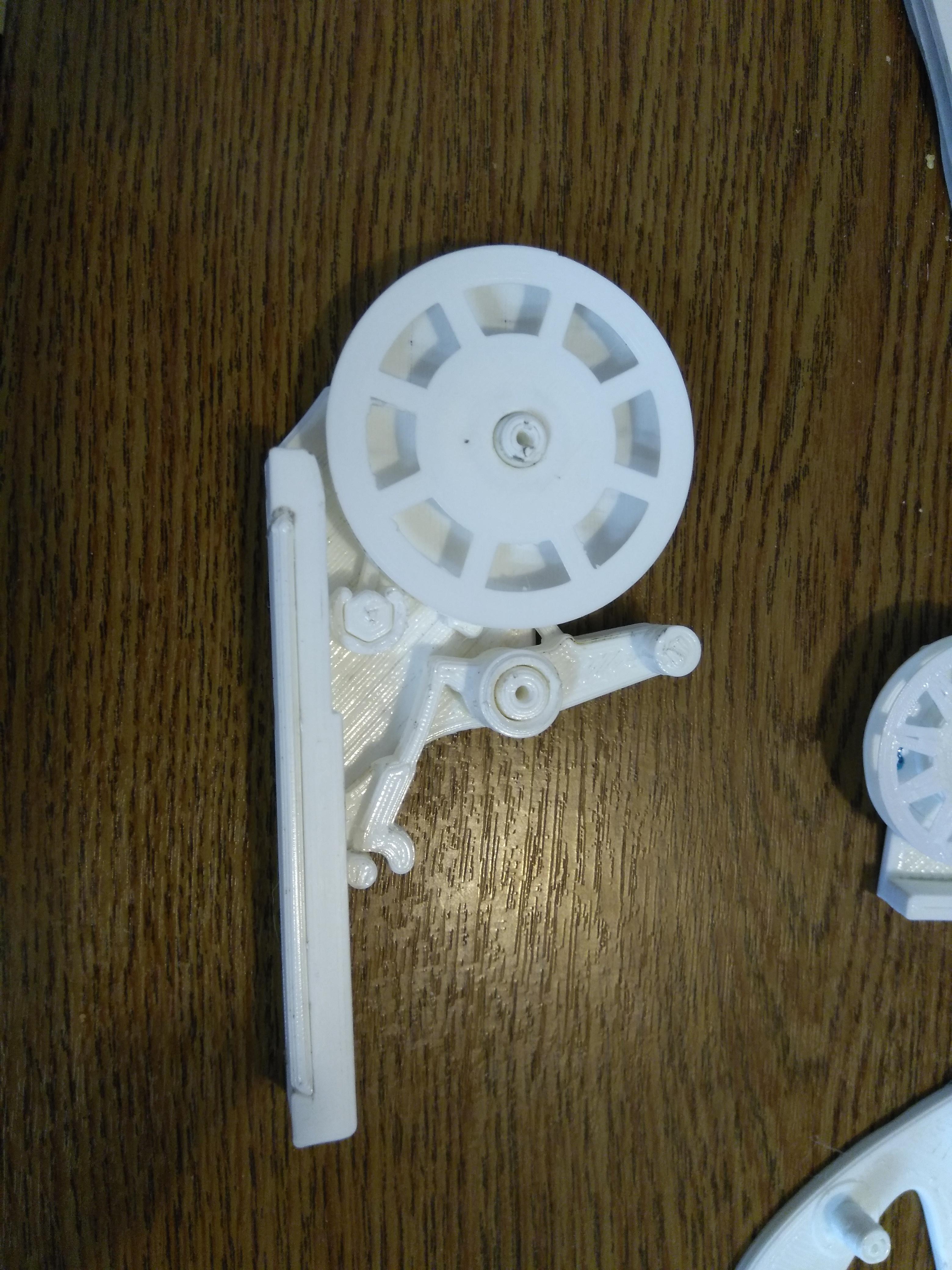
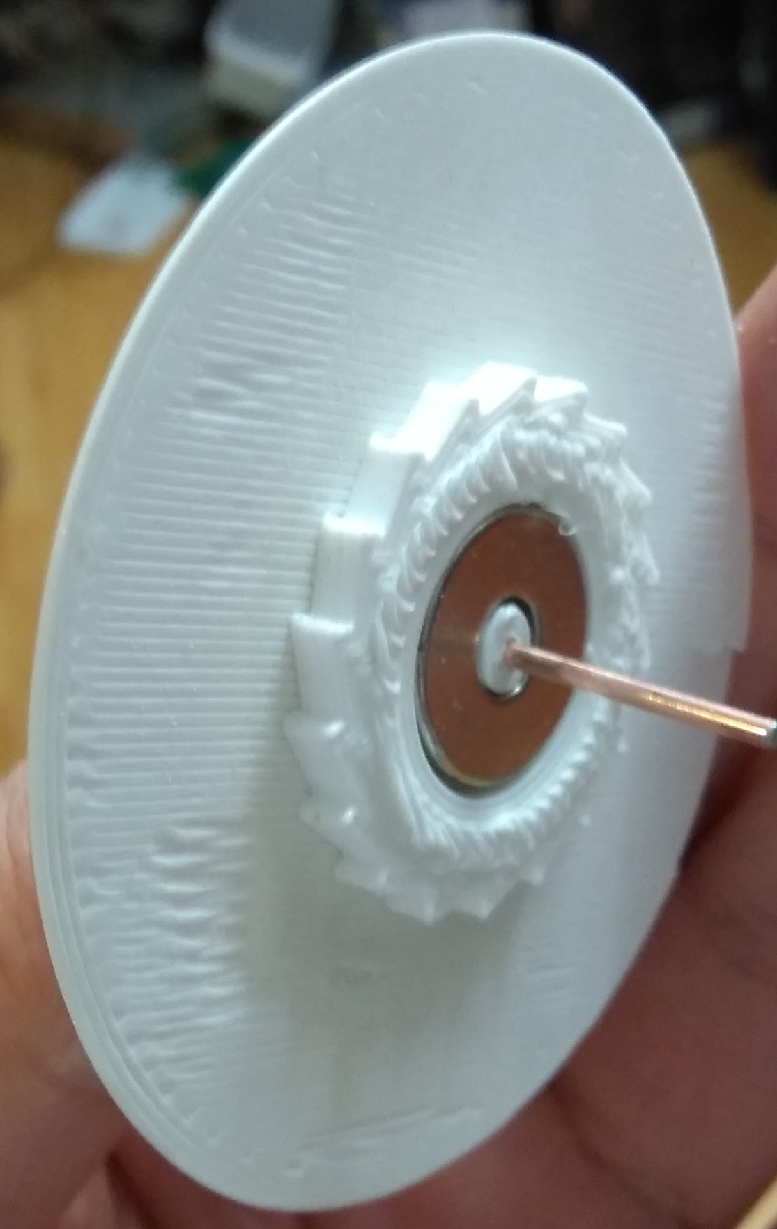
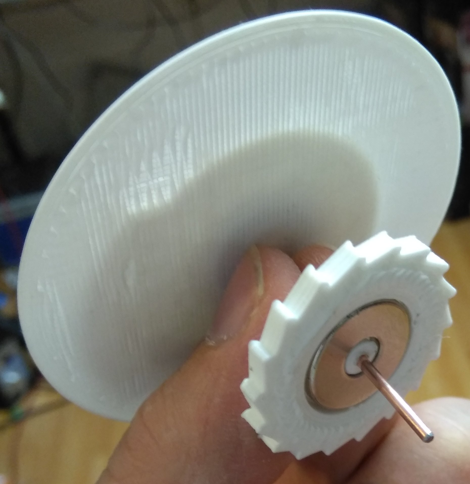
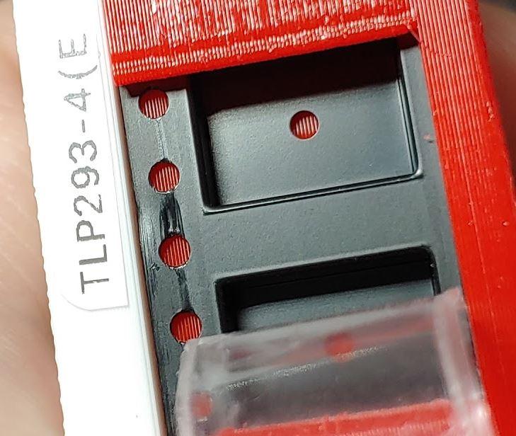
> ??? Where the pin is? I can't see it. Do you have some closeup photo of that part?
This one was already used for dozens if not hundreds of parts:
> I do print with white PLA. Seems that this one is to sticky. Maybe I need to try with PETG.
No, PLA will not work. It is too brittle, things will break. No
wonder you broke the lever.
Yes, go for PETG, it is day and night! I never use PLA anymore except for kiddy stuff like "sparkling gold filament" etc. ;-)
> Will try again but sadly can't believe that this part can be made reliable.
Therapy for those metal fanatics that doubt plastic in general:
- Take an empty PET bottle of carbonated water (also known as soda water, sparkling water, fizzy water, water with gas, or however you call it where you're from). Still water bottles won't work (I think they are often not even made from PET).
- Take a moment to study how thin the
bottle wall is.
- Now with your bare hands and teeth
(be careful!) try to rip it into two pieces. Fast!
- Time it. Make a video and post it,
if you dare ;-)
--
You received this message because you are subscribed to the Google Groups "OpenPnP" group.
To unsubscribe from this group and stop receiving emails from it, send an email to openpnp+u...@googlegroups.com.
To view this discussion on the web visit https://groups.google.com/d/msgid/openpnp/7376c0b6-4af5-4915-b503-3c14ba394c45%40googlegroups.com.
Slavko Kocjancic
> Hi Slavko
>
> /> ??? Where the pin is? I can't see it. Do you have some closeup photo
> of that part?/
>
> This one was already used for dozens if not hundreds of parts:/
I forget to post. I already find the culpruit. I used 0.8mm nozzle on my
printer and slicer just "erase" that pin. I ordered some finer nozzles
to see differnce.
> /
>
>
> />//I do print with white PLA. Seems that this one is to sticky. Maybe I
> need to try with PETG./
> No, PLA will not work. It is too brittle, things will break. No wonder
> you broke the lever.
the lever seem's to be a little bit to flimsy now. It does radial twist.
Seems that PLA is to britle for spring and PETG to soft? Maybe need to
try another brand.
>
> Yes, go for PETG, it is day and night! I never use PLA anymore except
> for kiddy stuff like "sparkling gold filament" etc. ;-)
>
>
> reliable./
> I'm currently bogged down with other stuff. But I will do the promised
> "burn-in-test", like I said and explained here:
>
> https://groups.google.com/d/msg/openpnp/VDEKlvYKfTY/NOwMW3xWAQAJ
>
with bigger diameter the clutch works way better.
I belive thay you target to 20m of cover tape and you get that with
reeel with 24mm inner and 57 outer diameter. And this mean that in worst
case when spool is empty you need up to 100g force. But when spool is
near full you need 230g force not including friction. I thing that
ratchet driving dog should be little stronger for that.
And I test other aproaches too. I do test print with spool with 50mm
inner diameter and 71mm outer diameter. and in this case only 145g force
is needed when spool is full. And of course a lot more space in hub for
clutch. So 14mm wider outer diameter do a lot! Even 40/64 will do beeter
and just 7mm bigger diameter.
And I do burn test with blocked clutch. I connect drill to clutch and
drive that at 250RPM for one hour. That means around 100m of cover tape.
The temperature rise to 40 degre/C. At start the clutch have 5N/cm force
and after test just 1.5N/cm. And wear is clearly visible. Test done with
PLA and 50mm clutch.
ma...@makr.zone
;-) no comment.
_Mark
Marek T.
How do you think? If you got what I mean :-).
ma...@makr.zone
Hi Marek
I need to push and to pull (not shown in the gif). Hence
the name ;-)
Remember we talked about it, for a 0402 we need to feed only every second pick, so we can't do it without extra moves.
But the feeder does not need an extra move in X. Only in Y and Z (assuming a "South" feeder).
https://youtu.be/5QcJ2ziIJ14?t=255
_m
Scott Wilson
Marek T.
Pity. I must print it and look if can improof it in acc to my dreamings ;)
Marek T.
bert shivaan
Kraft - typo error of damned phone...
--
You received this message because you are subscribed to the Google Groups "OpenPnP" group.
To unsubscribe from this group and stop receiving emails from it, send an email to openpnp+u...@googlegroups.com.
To view this discussion on the web visit https://groups.google.com/d/msgid/openpnp/5f051347-76a1-4ec7-ad5e-f6b9a15eb34a%40googlegroups.com.
Slavko Kocjancic
> Can anyone explain the point of running the waste spool at 250 RPM for
> an hour?
> I mean the use case for this is to only move per feed correct?
>
And with that I simulated 5 full rels used.
bert shivaan
--
You received this message because you are subscribed to the Google Groups "OpenPnP" group.
To unsubscribe from this group and stop receiving emails from it, send an email to openpnp+u...@googlegroups.com.
To view this discussion on the web visit https://groups.google.com/d/msgid/openpnp/d091188e-028a-ba6e-6bbb-b38ab8175371%40gmail.com.
Slavko Kocjancic
> but it spun too fast and generated heat that will never happen in real use
>
that condition I can call that is good for 2 reels. Under normal
condition probably more. At least clutch. Other weak point is probably
dog that drive ratcher.
Keith Hargrove
ma...@makr.zone
Very good point. If this acts up, I will make room for gluing
some into the drum.
For clutch a bit of pinched felt has been the standard for 100's of years. Almost every cassette tape deck use felt. I bet other bits of fabric might work but felt is king for low speed clutches.
--
Slavko Kocjancic
I did test with felt just few days ago. I squished it with two magnets.
The friction is constant. If the felt is on bed side of print (smoth)
the friction is little low. If I put felt on top side on print the
freiction is to high. I did try to sand bed side of print and that's
come just right. But I'm in doubt how long will keep that. Need to make
burn test.
I did try bare PLA to PLA (base plates touching) and got near zerro
friction (but magnet pressing like mad it's hard to separate them)
Then I try various material betwen disks. Inded felt works best.
Test parts shown.
eSlavko
ma...@makr.zone
Not sure I understand. We don't want it to clutch against the
feeder base, only against the ratchet. I probably misunderstand.
_Mark
Forget to say that in this axial way the both flanks of spool rotate and are limited with slip clutch. In original design one flank is direct driven and other slip limited.
--
You received this message because you are subscribed to the Google Groups "OpenPnP" group.
To unsubscribe from this group and stop receiving emails from it, send an email to openpnp+u...@googlegroups.com.
To view this discussion on the web visit https://groups.google.com/d/msgid/openpnp/302ed708-638e-4371-a41e-a62fe6d6fd13%40googlegroups.com.

Ray
This is really awesome! Thank you for designing and sharing it :)
I had to tweak the scad settings a little for my printer (so many options, it’s great!) and I found one thing that isn’t working for me. I had to set a positive “play” value to get the cylinder of the Tape Chute (that it pivots on) to fit into the Base Plate (making the cylinder smaller), but doing so increases the diameter of the half circle nub on the Tape Chute that snaps into the Base Plate to keep it in is normal position. I expected that nub to get smaller with a positive value like the cylinder does. As is I can’t get the Tape Chute to fit in both places with the same “play” value. Is the “play” value change for the Tape Chute nub inverted? Or am I missing something?
Thanks!
ma...@makr.zone
Hi Ray
Glad its useful :-)
Yes, I inverted this by mistake!
The rule is this: all the small parts of the Phase II have the
play, so you can adjust it and reprint only the small part.
It should be fixed:
https://github.com/markmaker/PushPullFeeder.git
_Mark
--
You received this message because you are subscribed to the Google Groups "OpenPnP" group.
To unsubscribe from this group and stop receiving emails from it, send an email to openpnp+u...@googlegroups.com.
To view this discussion on the web visit https://groups.google.com/d/msgid/openpnp/b1c9a185-03b0-490e-9cda-bbd87b43f796%40googlegroups.com.
Ray
On Tuesday, May 19, 2020 at 10:36:07 PM UTC-7, ma...@makr.zone wrote:
Hi Ray
Glad its useful :-)
Yes, I inverted this by mistake!
The rule is this: all the small parts of the Phase II have the play, so you can adjust it and reprint only the small part.
It should be fixed:
https://github.com/markmaker/PushPullFeeder.git
_Mark
Am 20.05.2020 um 00:50 schrieb Ray:
--This is really awesome! Thank you for designing and sharing it :)
I had to tweak the scad settings a little for my printer (so many options, it’s great!) and I found one thing that isn’t working for me. I had to set a positive “play” value to get the cylinder of the Tape Chute (that it pivots on) to fit into the Base Plate (making the cylinder smaller), but doing so increases the diameter of the half circle nub on the Tape Chute that snaps into the Base Plate to keep it in is normal position. I expected that nub to get smaller with a positive value like the cylinder does. As is I can’t get the Tape Chute to fit in both places with the same “play” value. Is the “play” value change for the Tape Chute nub inverted? Or am I missing something?
Thanks!
You received this message because you are subscribed to the Google Groups "OpenPnP" group.
To unsubscribe from this group and stop receiving emails from it, send an email to ope...@googlegroups.com.
Ray
I'll probably just get it to print with small bevels ;)
On Thursday, May 7, 2020 at 11:23:54 AM UTC-7, ma...@makr.zone wrote:
Hi Melitonas
My gut feeling is that you must solve this problem with your printer rather than trying to mend it in the model. Are you printing in PETG? I'm just asking because I hat an awful experience with ABS. ABS didn't work at all.
If you have problems with PETG please try using a adhesive Spray. It works wonders!
Also I don't really understand your question. The bevel will normally help against warp and not worsen it.
Having said all that, you can change how the model will be beveled.
First there is the bevel_z variable. It controls most large bevels. It is set to two layer height by default. Change it as you like.
And then there is the default parameter value for bevel in beveled_extrude().
It is set to one layer height by default. Change it as you like.
_Mark
Am 07.05.2020 um 17:19 schrieb Melitonas:


hello,
trying to print it, but the edges are warping badly.
how to disable the bevel in openscad? I will to add the brim in prusa slicer.
--
You received this message because you are subscribed to the Google Groups "OpenPnP" group.
To unsubscribe from this group and stop receiving emails from it, send an email to ope...@googlegroups.com.
To view this discussion on the web visit https://groups.google.com/d/msgid/openpnp/6321c8a0-a633-4c6d-967c-5662d00e585a%40googlegroups.com.

Alexander Goldstone
On Friday, April 10, 2020 at 10:14:28 PM UTC+1, ma...@makr.zone wrote:
Hifor those interested, I made a new feeder class PR:Watch the movie:With OCR part recognition, one-click setup and other cool features:_Mark
ma...@makr.zone
Hi Alexander
Your assumptions are right. The BlindsFeeder shouldn't be printed
too long anyway, otherwise the tolerances of the tape pitch
against the blinds pitch will create problems (allowed
manufacturing tolerances by EIA standard).
For the PushPullFeeder, you can choose which elements to print in
the model but as they are arranged for the larger print bed,
you'll need to right click on the object in PrusaSlicer and choose
Split / To objects function
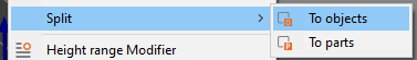
Then the Arrange function. It can automatically arrange stuff on the bed.

_Mark
--
You received this message because you are subscribed to the Google Groups "OpenPnP" group.
To unsubscribe from this group and stop receiving emails from it, send an email to openpnp+u...@googlegroups.com.
To view this discussion on the web visit https://groups.google.com/d/msgid/openpnp/f4a7f832-9255-470c-ac27-4c33b014930a%40googlegroups.com.
Alexander Goldstone
To unsubscribe from this group and stop receiving emails from it, send an email to ope...@googlegroups.com.

Harjit Singh
To view this discussion on the web visit https://groups.google.com/d/msgid/openpnp/3089f14a-f597-9d01-3423-237038d4b185%40makr.zone.
ma...@makr.zone
Hi Harjit
First, just to avoid confusion, I'd like to point out that I'm now talking about the BlindsFeeder, not the PushPullFeeder, i.e. we're in the wrong thread :)
https://makr.zone/new-openpnp-blindsfeeder/353/
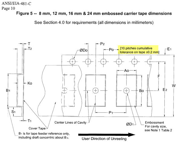
The EIA standard allows for some tolerance in the pitch of the
pockets and sprocket holes. The more pockets you line up, the more
these errors accumulate. This is irrelevant for all transporting
feeders (e.g. the PushPullfeeder), because of the sprocket holes
obviously having the same errors as the pockets and them
constantly correcting the position. But in the laid out
BlindsFeeder the accumulation may become relevant, at least for
very long 0402 tape feeders. The standard allows for 0.2mm error
on 10 pitches, so after 25 parts (=only 50mm on 0402 tape), the
1mm pocket could theoretically be half obstructed by the blinds
cover and picking become impossible. I'm sure only a fraction of
these tolerances is usually exploited by manufacturers these days,
and I guess feeders up to ~150mm are fine (they all were in my
tests). But it's still just something to keep in mind. For larger
parts/pitches you can make longer feeders.
_Mark
To view this discussion on the web visit https://groups.google.com/d/msgid/openpnp/CAEm8oESnnQuw65wrL7ToVsxOSor7c7g4aN5h8X8X%2Br8GQbXvfg%40mail.gmail.com.

Morpheus
Looking forward to try them
Ray
Ray
ma...@makr.zone
Hi Ray
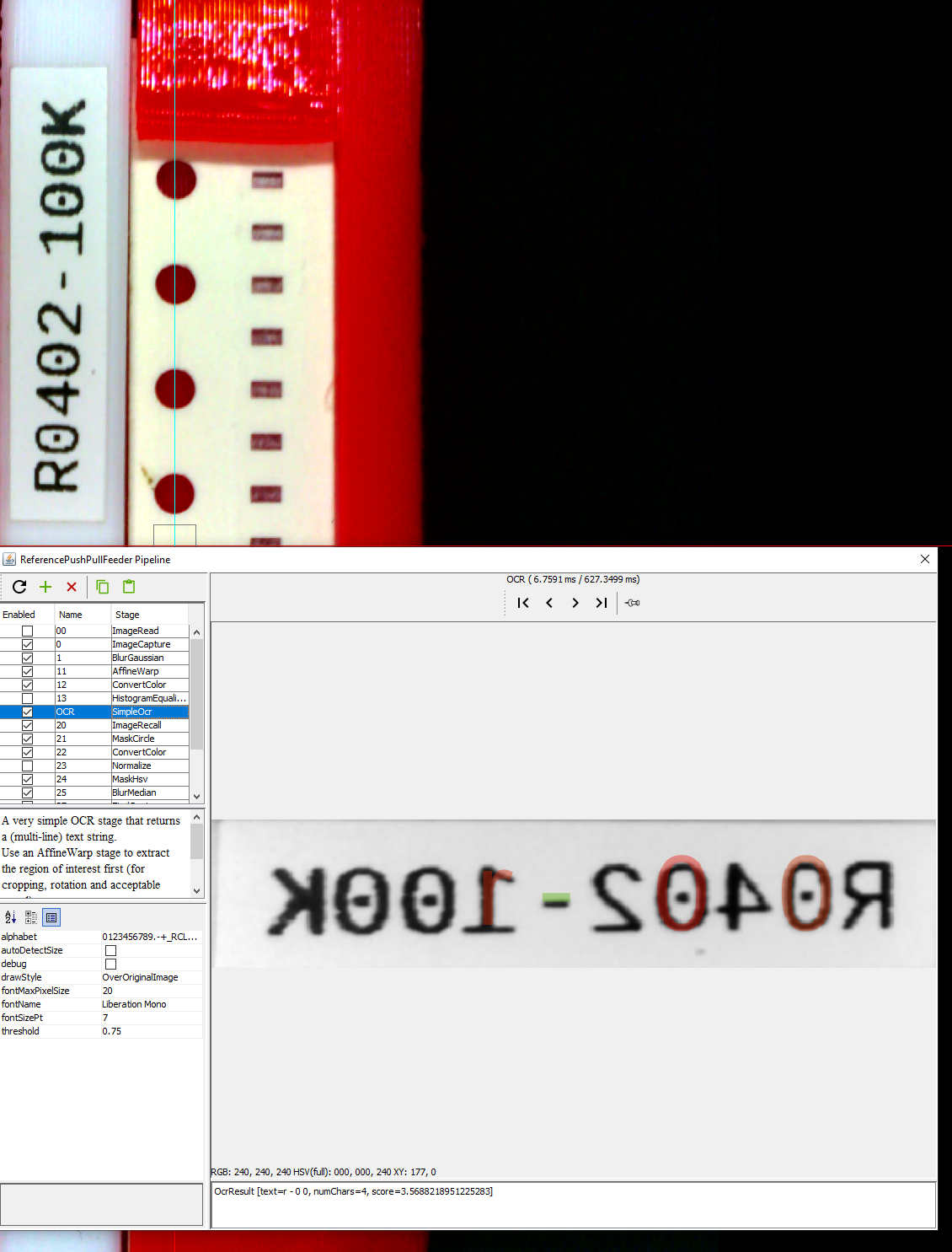
It must be the OCR Region of Interest (ROI) setup. If you select
the wrong corners / in the wrong order this may happen.
https://youtu.be/5QcJ2ziIJ14?t=40
Read the text underneath the camera view. If the text is bad, please report back so I can improve it. I'm not an English speaker :).
_Mark
--
You received this message because you are subscribed to the Google Groups "OpenPnP" group.
To unsubscribe from this group and stop receiving emails from it, send an email to openpnp+u...@googlegroups.com.
To view this discussion on the web visit https://groups.google.com/d/msgid/openpnp/2a05901b-e7af-4a3c-97ef-4820990e840eo%40googlegroups.com.
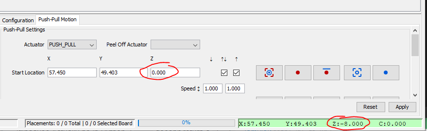
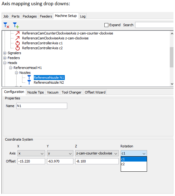
ma...@makr.zone
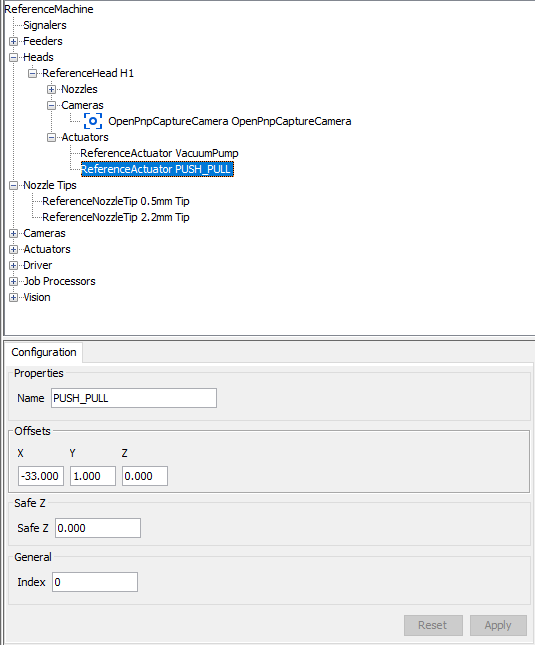
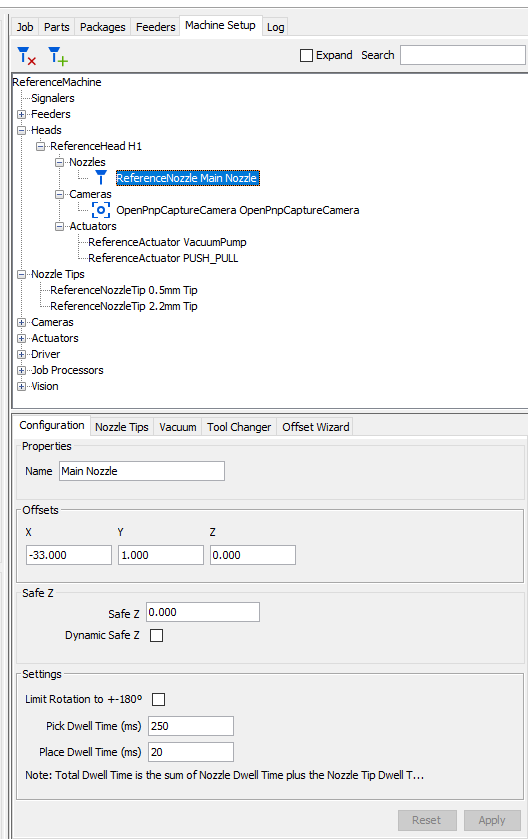
You need to add the Actuator to the Z axis mapping.
Like the Nozzle, but with the ID of the Actuator:
https://github.com/openpnp/openpnp/wiki/GcodeDriver%3A-Axis-Mapping#mapping-axes-to-headmountables
This will be much easier in the future :-)
I'm currently developing this:
https://groups.google.com/d/msg/openpnp/bEVZvYoXO98/xi__Nk-dAgAJ
_Mark
--
You received this message because you are subscribed to the Google Groups "OpenPnP" group.
To unsubscribe from this group and stop receiving emails from it, send an email to openpnp+u...@googlegroups.com.
To view this discussion on the web visit https://groups.google.com/d/msgid/openpnp/035d876e-4bad-4e75-8985-871758227e9eo%40googlegroups.com.
Ray
On Wednesday, June 10, 2020 at 10:22:49 AM UTC-7, ma...@makr.zone wrote:
Hi Ray
It must be the OCR Region of Interest (ROI) setup. If you select the wrong corners / in the wrong order this may happen.
https://youtu.be/5QcJ2ziIJ14?t=40
Read the text underneath the camera view. If the text is bad, please report back so I can improve it. I'm not an English speaker :).
_Mark
Am 10.06.2020 um 16:40 schrieb Ray:
--I'm trying to figure out why my part label is being mirrored in the vision pipeline. This happens with default pipeline settings. It first appears mirrored in the AffineWarp stage. The mirroring stops the OCR from reading the label correctly.
Any ideas?
Thanks for the help
You received this message because you are subscribed to the Google Groups "OpenPnP" group.
To unsubscribe from this group and stop receiving emails from it, send an email to ope...@googlegroups.com.
Ray
To unsubscribe from this group and stop receiving emails from it, send an email to ope...@googlegroups.com.

Gabe Balles
ma...@makr.zone
Hi Gabe
it is true that the friction wheel is the Achilles heel of the
whole construction and I can well imagine that "blobs/zits" etc.
can make finding the right balance impossible.
Have you tried using different filament? I had some filaments
that had a sticky "rubber" on "rubber" friction behavior that
didn't work. Others are had more of a "wax on wax" feel and they
work much better. The best so far is Extrudr PETG, but Prusament
PETG worked too. You can tell with the test print axles. If the
one with no wiggle exhibits a strong "creak", the filament is no
good.
Someone rightfully pointed out that felt has a long
tradition as a slip clutch material. I should perhaps investigate
into modifying the model for felt disc friction...
Any chance you could upgrade on the 3D printer? From the many
difficulties described in this thread, I'm starting to feel like a
spoiled child with my PRUSA i3 MK3s. I spent so much time making
the model parametric and versatile for everybody and now it seems
to turn out it only works on a (relatively) expensive printer that
no one seems to be able or willing to afford. It's a bit
frustrating.
:-(
_Mark
--
You received this message because you are subscribed to the Google Groups "OpenPnP" group.
To unsubscribe from this group and stop receiving emails from it, send an email to openpnp+u...@googlegroups.com.
To view this discussion on the web visit https://groups.google.com/d/msgid/openpnp/5555b238-62ce-42c8-b6d1-cb2201169df1o%40googlegroups.com.
bert shivaan
To view this discussion on the web visit https://groups.google.com/d/msgid/openpnp/c2ad90ea-d983-e786-c760-5fa4962cb5c5%40makr.zone.
bert shivaan
ma...@makr.zone
Thanks, bert, for the uplift :-)
> Mark I am not convinced it is the printer. think it has to do with experience printing more so.
That's the thing: I'm not an experienced 3D printer. BlindsFeeder is my very first real creation, PushPull the second. The PRUSA just always worked. The only thing I had to figure out, really, was using the spray adhesive. And, like I said, the filament is very important for the friction properties (in the BlindsFeeder as well, btw).
I may have gained considerable knowledge about precision printing
while retaining good speed, but never any "blobs/zits"or similar
stuff. If I look at close-ups of some prints others do here in the
group I must say it is often day and night...
> OOPs, I have only tried the blinds feeder, but I assume your high quality is in both places
No, the PushPullFeeder is much, much, much more
advanced. :-)
_Mark
To view this discussion on the web visit https://groups.google.com/d/msgid/openpnp/CA%2BKNHNxxoPaLhrPA1fEV2ua%2ByaGWSM6RTRF1O_S87trC21npHA%40mail.gmail.com.
Gabe Balles
Juan-Antonio Søren E. Pedersen
To view this discussion on the web visit https://groups.google.com/d/msgid/openpnp/1b67474e-5f96-9150-4bd2-e56372f47fb7%40makr.zone.

Michael Anton
ma...@makr.zone
Thanks, Gabe.
There will always be the problem, that the cover tape spool needs
some sort of slip clutch, ratchet or similar (if not controlled
electronically).
I like the idea of dirt cheap feeders, where I can keep the reels
loaded all the time. So a full electronic feeder is out of the
question. The only "next step" solution I see, is mounting the
feeder electronics on the head i.e. two motors/gears that are
coupled to feeder cogs when the head is over it and two sensors,
one seeing the sprocket hole, the other feeling the cover tape
tension.
_Mark
--
You received this message because you are subscribed to the Google Groups "OpenPnP" group.
To unsubscribe from this group and stop receiving emails from it, send an email to openpnp+u...@googlegroups.com.
To view this discussion on the web visit https://groups.google.com/d/msgid/openpnp/6ca6a9d7-05f9-4391-a783-df2f0951ebfbo%40googlegroups.com.
Morpheus
Printing with 0.28mm layer height and 0.47 width, the finesse is other worldly.
No clogging.
On my Bowden here, i retract 5 mm and prime 0.1mm2 without z jump. Costing set to 0.2mm2. No stringing, no blobs.
Ray
Gabe Balles
Ray
Ray
ma...@makr.zone
> I printed a 12mm tape version of the feeder and didn't have any issues or have to do any additional tweaking :)
So cool!
> I'm having trouble getting it setup in openpnp
however. The parts are every 8mm so the lever needs to be
actuated twice for each part. I set the Part Pitch to 8mm and
the Feed Pitch to 4mm, which I was assuming would make it
actuate the lever twice, but it still only moves it once, so
half the time it tries to pick between the parts.
Your assumption is correct. I don't understand why this shouldn't work, the code is simple:
long feedsPerPart =
(long)Math.ceil(getPartPitch().divide(getFeedPitch()));
long n = getFeedMultiplier()*feedsPerPart;
for (long i = 0; i < n; i++) { // perform multiple
feeds if required
If anything the ceil() would create too many actuations due
to floating point inaccuracies.
Are you sure you pressed Apply?
Could you send me your machine.xml?
_Mark
--
You received this message because you are subscribed to the Google Groups "OpenPnP" group.
To unsubscribe from this group and stop receiving emails from it, send an email to openpnp+u...@googlegroups.com.
To view this discussion on the web visit https://groups.google.com/d/msgid/openpnp/a89efa33-7ef5-4624-ba0e-2550aee893dbo%40googlegroups.com.
ma...@makr.zone
Hi Ray
It just occurred to me that this might be the culprit. In the
video I forgot to select the middle switch on Mid 3 Location:
https://youtu.be/5QcJ2ziIJ14?t=198
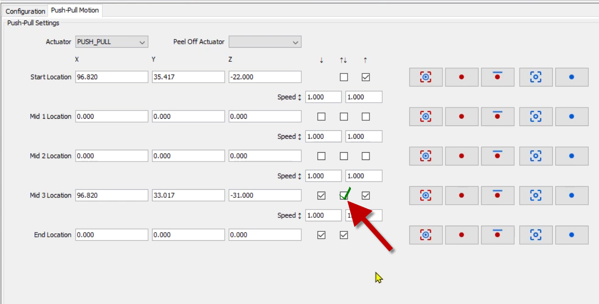
The middle lane of switches tell the feeder which segments to
move back for multi-actuation i.e. there is no need for it to go
all the way back to the start (no withdrawal/insertion to/from
Safe Z needed).
But obviously if Mid 3 Location is missing it does nothing for
the multi-actuations.
Sorry about that!
_Mark
To view this discussion on the web visit https://groups.google.com/d/msgid/openpnp/ab5e295a-1601-7691-6831-8aa593742c44%40makr.zone.
Ray
ma...@makr.zone
> My printer is currently printing parts for a 16mm tape feeder now. Have a lot of SOIC16 optos to place ;)
I keep my fingers crossed.
_Mark
Ray
ma...@makr.zone
Hi Ray
> 16mm tape feeder seems to be working out just as well
mechanically :)
Exhaling! I'm glad this seems to work out! I was a bit worried
about the spring driving the ratchet (that doesn't grow in
size/strength). Does the cover tape pulling resistance increase
much with tape width? (I know that's probably hard to
measure/judge)
> It might be starting to push the limits for some of the smaller "tower" features of the print, but I've never needed tape any wider than this anyway.
Some of them have holes, so you can add metal pins/screws to
reinforce if needed on these large tape widths. But some have not,
if one of those breaks, please report, maybe it can be improved.
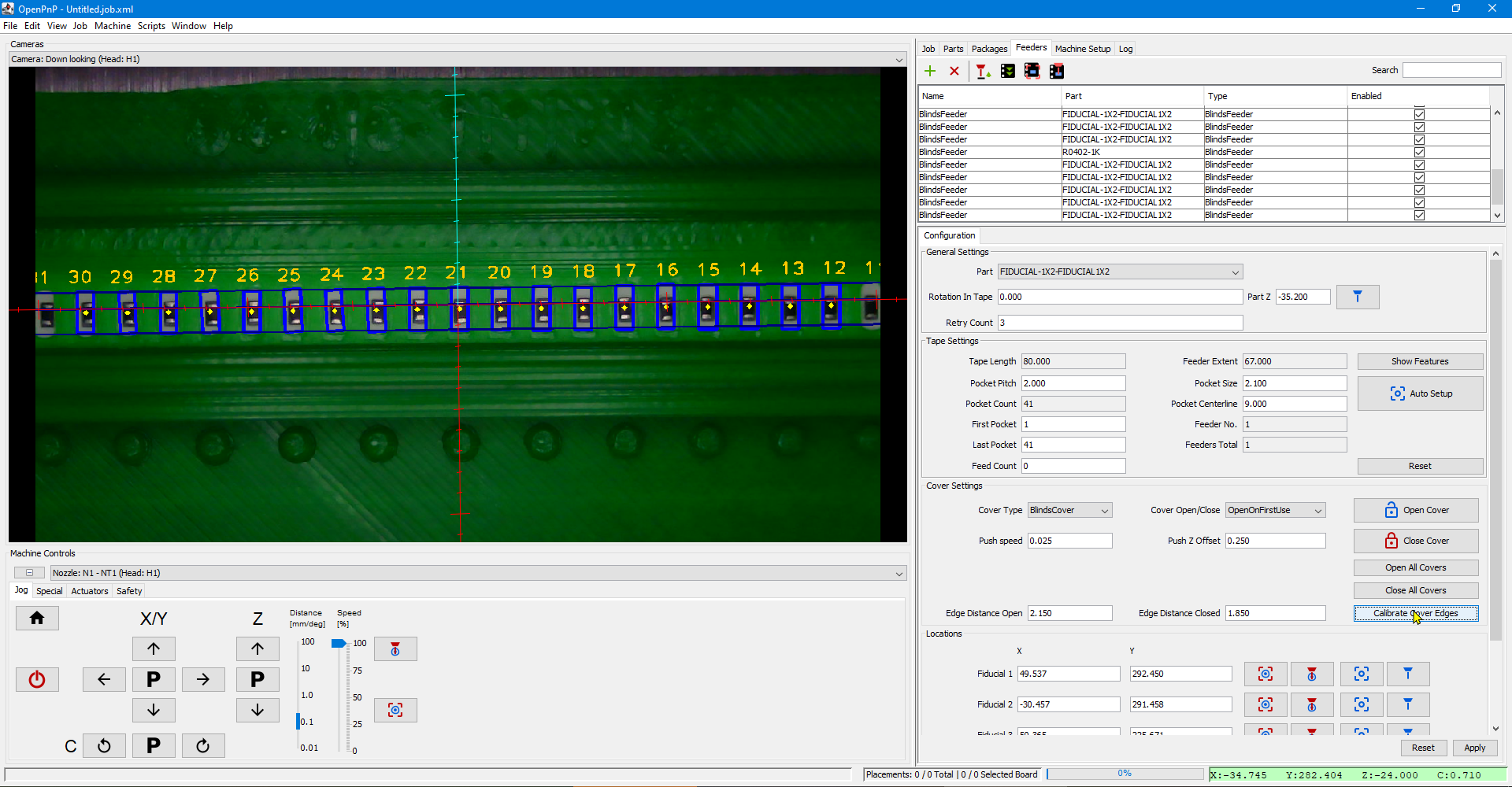
> I'm having trouble setting up the feeder in openpnp
though. The MaskCircle in the pipeline is too small to see the
tape holes, which is fine and easy to fix, but the edited
pipeline keeps getting overridden when I use the auto setup.
Ahhh... I must really find the time to document that on the Wiki.
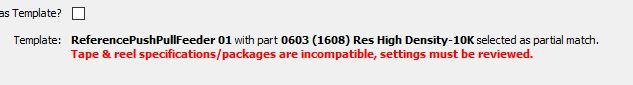
There is a switch "Use this one as template" that makes this
feeder the "master" in terms of setting among all those with the
same package (by default, see below). When you are later
adding a new feeder, or when you are using Auto Setup or cloning
explicitly, this template is in effect.
So you switch it on and then change whatever settings you like
(including the pipeline) and then redistribute the setting to the
other feeders in the group.
I rudimentarily show this in the video here:
https://youtu.be/5QcJ2ziIJ14?t=404 (sorry about the stammering)
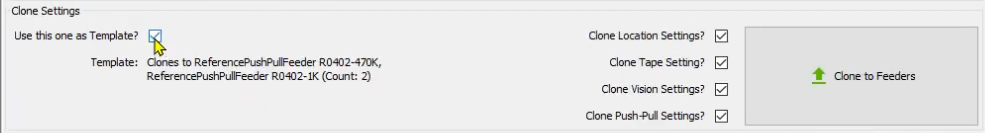
Note that the switches besides the large "Clone" button are only
effective when you are pressing the button, not when you add a new
feeder or use AutoSetup.
There is a "Tape Specification" on the Packages tab, that allows
even larger grouping:
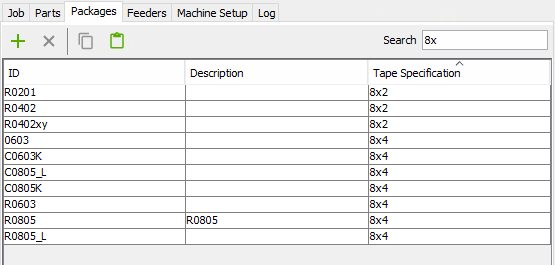
All the packages that have the same Tape Specification (it's just
a string) are handled as one group with shared settings.
So for instance I tag all the 8mm wide, 4mm pitch tapes as "8x4"
and I only need to setup one template feeder for all
variants of 0603, 0805 packages etc..
More background here:
https://github.com/openpnp/openpnp/pull/987#issuecomment-615184748
https://github.com/openpnp/openpnp/pull/987#issuecomment-616076897
_Mark
--
You received this message because you are subscribed to the Google Groups "OpenPnP" group.
To unsubscribe from this group and stop receiving emails from it, send an email to openpnp+u...@googlegroups.com.
To view this discussion on the web visit https://groups.google.com/d/msgid/openpnp/d22cb823-786f-47be-84c0-d17771c8a0c9o%40googlegroups.com.
Ray
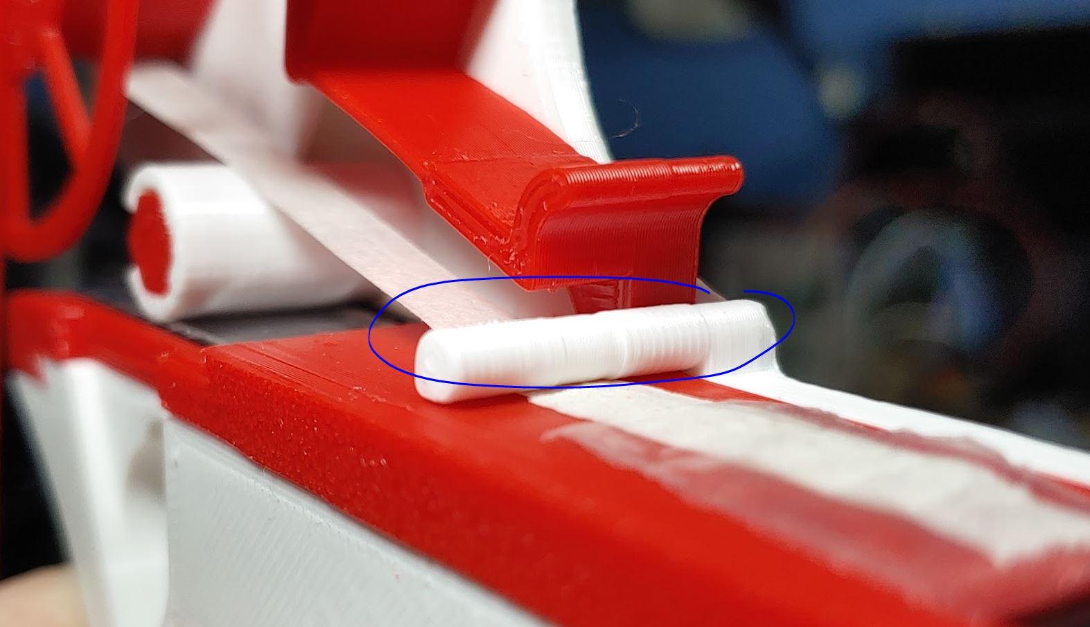
I started having issues with the tape not advancing because the thorn was carving a kind of groove into the thin plastic tape and was unable to grip it anymore. This is partly because I was running the same section multiple times for testing. But removing the dog groove recess didn't give the tape anyway to move out of the way and seems to have stopped the grip from slipping even in the already worn sections.
It is a bit surprising because the dog fits so nicely in that groove when you just hold the parts together... Maybe the level of the part of the base plate that the advancement lever rides on for my prints is just a bit higher than the tape insert, making the dog not reach to the bottom of the groove when its all assembled? Hard to tell, and the tape is so thin it doesn't need much to slip beneath the dog.
If I create two Push-Pull feeders using 16x12 tape spec parts, then I can edit the pipeline in one, and when I auto setup the other it grabs that new working pipeline. Then I can make one of them the template and everything is good from there. I think I have to use this order for setup since you can't run the auto setup when the feeder is marked as a template.
I'm not sure the best way to handle that. It seems as though if there is no tape spec match that it shouldn't try to pull data from another feeder definition and just use what has been manually configured for the new feeder, but then it wont pull the Push-Pull Motion positions, which are valid, and would have to be manually entered again... Maybe it should not pull any data automatically and instead you can use the clone button to get better starting values before manually editing it? Not sure how intuitive that is though...
ma...@makr.zone
Hi Ray
sorry to reply so late (on holidays :-)
> The only small issue I have is a bit of a chicken and egg
thing.
That's exactly the thing here. "Auto Setup" is really thought to be the very first action in a feeder's life. At that point the correct part is not yet know, as we are completely lazy and want OCR to grab it. With the part not yet known, you don't have the package much less the tape specification. So what the code does is just grab any one template (I think the one closest in X/Y) and clone the OCR pipeline from it, then try and recognize the part, then clone again from the right template. But the second clone will obviously fail if it is the "first of a kind".
You should not (have to) press Auto Setup after that initial go.
The exact sprocket holes will be calibrated as needed using the
same vision process.
If you moved/exchanged the feeder to a new location or informal
"slot", just press the OCR button. It will calibrate the sprocket
holes, OCR-recognize the part, and if a feeder with that part
already exists, it will yank it to the new location. You can do it
for all the feeders at once and it will reshuffle the feeders to
their new locations, disable those that are not found anymore and
create new ones as needed. This may still need a bit of practical
testing though...
_Mark
--
You received this message because you are subscribed to the Google Groups "OpenPnP" group.
To unsubscribe from this group and stop receiving emails from it, send an email to openpnp+u...@googlegroups.com.
To view this discussion on the web visit https://groups.google.com/d/msgid/openpnp/8a467bfe-2ac0-4db4-9c27-016617b9787co%40googlegroups.com.