ReferenceStripFeeder - Rotation in Tape

Zdenko Stanec
I am preparing one of my biggest projects with 115 different types of components and I need some assistance so I limit potential issues as much as I can.
I know there were a few topics regarding these and I spend a few hours researching them same as GitHub but all I do just makes no sense to me.
I will cover it from the start so you can maybe see what I am missing.
First I have checked how component library/footprint should be made according to:


Zdenko Stanec

mark maker
Does this help? (see the Rotation in Tape)
https://github.com/openpnp/openpnp/wiki/ReferencePushPullFeeder#tape-settings
But I'm not sure it works the same way in ReferenceStripFeeder.
_Mark
--
You received this message because you are subscribed to the Google Groups "OpenPnP" group.
To unsubscribe from this group and stop receiving emails from it, send an email to openpnp+u...@googlegroups.com.
To view this discussion on the web visit https://groups.google.com/d/msgid/openpnp/254741d0-6395-44f8-86aa-247b4d6b4b6dn%40googlegroups.com.
Zdenko Stanec

mark maker
Hi Zdenko
Just to make sure we both understand it the same way, your diode is drawn like this in the library:
And it is like this in the tape with the sprocket holes at top (standard EIA-481-C orientation):

This is how BlindsFeeder and ReferencePushPullFeeder
work.
Unfortunately, (I just remembered) the ReferenceStripFeeder
is different, despite the documentation saying otherwise!
See this discussion:
https://groups.google.com/g/openpnp/c/KzO9afo3GlE/m/0fmRZBVkAwAJ
It is programmed like this in the code, i.e. you have to mentally
look at it with the sprocket holes to the right:

So this gives you +/-180° Rotation in Tape (for 180° it does not matter if plus or minus, you end up the same way).
I've improved the Wikis:
https://github.com/openpnp/openpnp/wiki/ReferenceStripFeeder#rotation-in-tape
https://github.com/openpnp/openpnp/wiki/ReferencePushPullFeeder#tape-settings
https://github.com/openpnp/openpnp/wiki/BlindsFeeder#rotation-in-tape
@Zdenko, please confirm, so I'm sure this now right. 😬
_Mark
To view this discussion on the web visit https://groups.google.com/d/msgid/openpnp/8bf5b0e4-7ab4-4dc9-bcae-b922bb792c82n%40googlegroups.com.
Zdenko Stanec
mark maker
Hi Zdenko,
STOP!
I just realized, the angled points are also swapped in the code
(they go against direction of unreeling, i.e. it is
reversed 180°). So the 0° tape orientation should actually be with
the sprocket holes to the left.
So in your diode case that would give you Rotation in Tape of
0°:
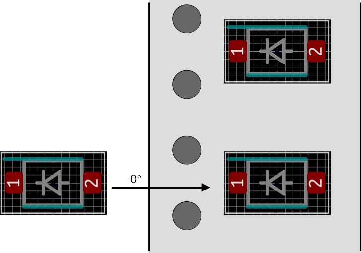
This would make sense insofar, as most feeders in the
default OpenPnP simulation are in this orientation, hinting
towards what Jason thought to be 0° when he developed this:


_Mark
To view this discussion on the web visit https://groups.google.com/d/msgid/openpnp/59613e97-383d-4f10-8d12-e3cc3aa304fbn%40googlegroups.com.
Zdenko Stanec
mark maker
> I think my placement was ok when orientation in the tape was 0 deg, but I will confirm it later.
That, together with my own tests, already confirms it at least
half-way. Thanks.
_Mark
To view this discussion on the web visit https://groups.google.com/d/msgid/openpnp/7a983f78-6796-4722-9686-982aa5036cecn%40googlegroups.com.
mark maker
Hi everybody,
IMPORTANT: affects all users of ReferenceStripFeeder!
Because of the recurring problems (see this thread and here),
I decided to fix it once and for all. All Rotation in Tape
settings are now uniform and conformant to the EIA-481-C industry
standard. Tape 0° is, when the tape has the sprocket holes on top,
see the "Quadrant designations".

Existing feeders are automatically migrated when you upgrade to
the new OpenPnP testing version from today (2022-06-10)
and later.
https://openpnp.org/test-downloads/
To make it clear: you do not need to do anything (just get
used to the new meaning, and don't be surprised when your feeder's
Rotation in Tape angles have magically changed by -90°.
https://github.com/openpnp/openpnp/wiki/ReferenceStripFeeder#rotation-in-tape
More details here:
https://github.com/openpnp/openpnp/pull/1429
If somebody has a huge problem with that change, please speak up now.
_Mark
To view this discussion on the web visit https://groups.google.com/d/msgid/openpnp/9dffe654-44a0-3e72-06fa-82a18e18cb26%40makr.zone.
Zdenko Stanec
mark maker
Thanks, and just to be extra sure: it did migrate that diode feeder to -90° automatically, right?
_Mark
To view this discussion on the web visit https://groups.google.com/d/msgid/openpnp/8b1c2247-63d5-4bd9-a9c3-55728e895023n%40googlegroups.com.
Zdenko Stanec

Ravi Ganesh
mark maker
> This change is very basic and will have adapting implications ...
True, but IMHO mild ones.
> both during setting up feeders in future ...
True, you need to get used to the new, uniform definition. But will you notice after a week? 😎
> ... and managing old feeders that is saved as .xml files
No. As soon as you load an old feeders.xml
into OpenPnP, even years later, it will be upgraded
correctly. The upgrade flag is stored with each feeder
individually.
> Migrating to a quadrant based method and doing away with the rotation terminology entirely would be good to users?
As far as I understood, this talk about quadrants is in fact
strongly related to absolute part orientation, more
specifically in which quadrant pin 1 is supposed to be,
in the tape. In order to be able to talk about an absolute
part orientation, we must also agree to the same absolute
part orientation in the ECAD, because that's where
we're getting our placement angles from.
But for ECAD absolute part orientation,
the underlying problem is that there was only limited industry
consensus as to what the canonical part zero orientation
is. There are documents such as this one...
... but AFAIK they are not universally adopted. And even if there
was such a standard, OpenPnP users will still use old ECAD
libraries, where parts are not standardized that way. For
instance, many Open Source project Eagle libs are simply wrong.
So for OpenPnP we shouldn't even start talking about absolute
part orientation. We should just tell people "look at the
orientation in your ECAD library". Then see how that
part/package/footprint is rotated
relative from there:

https://github.com/openpnp/openpnp/wiki/ReferenceStripFeeder#rotation-in-tape
So a relative rotation is IMHO very clear to understand, for any kind of part and ECAD. I don't see how quadrants could be clearer. For instances, ask yourself "in what quadrant is pin 1 for that diode?" 😇
Furthermore, I'm not sure if it is completely out of the question, that a tape could hold exotic parts at non-90°-step angles, relative to how you have it in your ECAD (e.g. coin cell holder, TO-sockets, odd-shaped connectors etc.)

_Mark
To view this discussion on the web visit https://groups.google.com/d/msgid/openpnp/516bf93e-8bf0-479d-81bd-dd20fd3d9558n%40googlegroups.com.
Ravi Ganesh

mark maker
Hi Ravi,
I agree, @vonnieda should ideally say what he thinks. I am
curious.
> EIA481 only talks about quadrants and nothing about orientation angle in feeder tapes.
Well, it defines the quadrants as "upper left", "upper right"
etc. in explicit relation to the sprocket holes being on top,
which in my book is quite definitive.
Plus it clearly indicates the "User direction of unreeling", which becomes the axis that corresponds to 0°.
Wikipedia:
"... in mathematics, the reference direction is usually drawn as a ray from the pole horizontally to the right, and the polar angle increases to positive angles for ccw rotations..."
https://en.wikipedia.org/wiki/Polar_coordinate_system#Conventions
But I'm open. If Jason argues for a different definition, we can also change the other two feeders around instead.
Note, when I programmed these other two feeders (BlindFeeder and ReferencePushPulllFeeder), I looked at the Wiki documentation of the ReferenceStripFeeder, which had it wrong and actually used the EIA-481 orientation. You can blame me to trust the Wiki. 😉
Old version:

To view this discussion on the web visit https://groups.google.com/d/msgid/openpnp/53bc6bba-02b4-4cb5-b64c-53a68991bc45n%40googlegroups.com.

Ian Arkver

Jason von Nieda
--You received this message because you are subscribed to the Google Groups "OpenPnP" group.To unsubscribe from this group and stop receiving emails from it, send an email to openpnp+u...@googlegroups.com.
To view this discussion on the web visit https://groups.google.com/d/msgid/openpnp/4b34190c-b334-4627-b592-4ba27707ef98n%40googlegroups.com.
Ravi Ganesh
Ravi Ganesh

mark maker
Hi Ravi,
Unless I'm missing something, your guidance shows exactly the new
system, assuming you have your parts in the ECAD drawn with the
industry part
zero orientation (which I assume your guidance
explains elsewhere).

Quadrant 1 Example:
The Zero Orientation document tells you, your ECAD orientation
must be like this (images from the document):

That is already the rotation in the tape (= 0°), with the
sprocket holes at the top.
Your guidance says 0° > CHECK 1
Quadrant 2 Example:
The Zero Orientation Doc tells you, your ECAD orientation must be
like this:

You need to rotate that 90° clockwise (= -90°) to get the
rotation in the tape, with the sprocket holes at the top.
Your guidance says -90° > CHECK 2
Quadrant 3 Example:
The Zero Orientation Doc tells you, your ECAD orientation must be
like this:
You need to rotate that 90° counterclockwise to get the rotation
in the tape, with the sprocket holes at the top.
Your guidance says 90° > CHECK 3
Quadrant 4 Example:
The Zero Orientation Doc tells you, your ECAD orientation must be
like this:
You need to rotate the part by 180° to get the rotation in the
tape, with the sprocket holes at the top.
Your guidance says 180° > CHECK 4
> The confusion starts right here. +90 or -90!!
- You still have the old OpenPnP version, but you are
reading the new Wiki. Then when you setup new feeders,
you have to add plus 90°, as
it clearly says in the last point described there.
- You have been setting up ReferenceStripFeeders for years
now, any you practically do it in your sleep. Then when you
setup new feeders, you need to get used to the new
angles which are the old angles minus 90°.
To view this discussion on the web visit https://groups.google.com/d/msgid/openpnp/0476e616-9313-431f-adb0-98cd1c86403en%40googlegroups.com.
surab...@gmail.com
Hi Mark,
I have captured the changes between the old and new system.
My concern is with ‘get used to the new angles” I think this is manageable.
Package | CAD orientation | Common Reel orientation | EIA-481 Quadrant | Rotation (old) | Rotation (New) |
Resistor/non-polarized capacitor |
|
| 2 | 0 | -90 |
Polarized Capacitor |
|
| 3 | 180 | 90 |
Electrolytic Capacitor |
|
| 3 | 180 | 90 |
Diode |
|
| 2 | 0 | -90 |
SOT23 (depreciated) |
|
| 3 | 90 | 0 |
SOT23 new |
|
| 3 | 180 | 90 |
SO8 |
|
| 1 | 90 | 0 |
TQFP |
|
| 1 | 90 | 0 |
QFN |
|
| 1 | 90 | 0 |
PLCC |
|
| 1 | 90 | 0 |
BGA |
|
| 4 | -90 | 180 |


