Help needed to connect the laser power supply to a new controller board
156 views
Skip to first unread message

aaron....@gmail.com
Jan 3, 2021, 12:30:26 PM1/3/21
to lasersaur
Hello everybody
I know shouldn't be posting here but I'm pretty desperate. The driveboard on my Lasersaur packed up and I don't have the soldering skills to make another one so I have bought my self an Openbuilds Blackbox motion controller (sorry, I really loved my old Lasersaur).
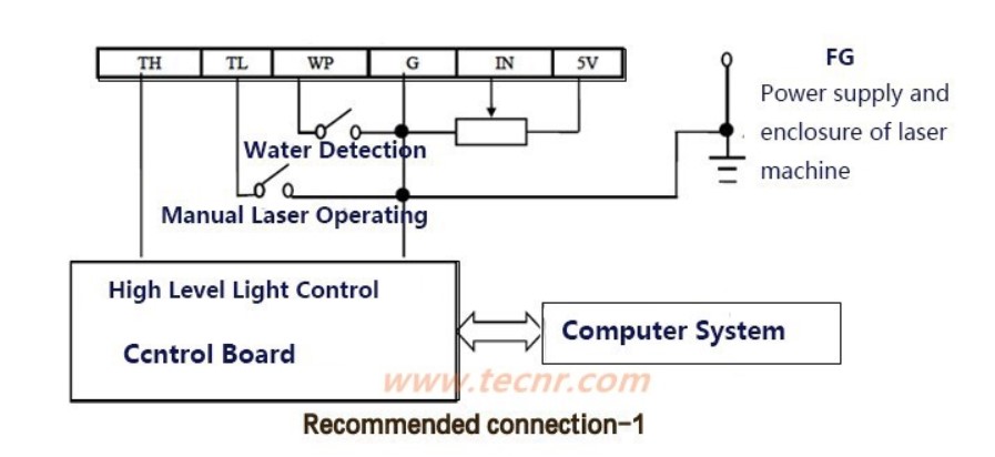
I have everything moving and homing okay, but electrical stuff isn't my strong point and I need help connecting the laser power supply up the the Blackbox and chiller. I have drawn and attached a diagram which I hope explains what I want to do. Could somebody please tell me where each wire should go.
Thanks In advance
Aaron

nicolas.de.barquin
Jan 5, 2021, 6:42:37 AM1/5/21
to lasersaur
Hello,
I was thinking to do the same at some point.
The setup is in a fablab and I use the blackbox for a cnc, I would like to unify the controls between both machines.
So here is my tough about that:
- Chiller and door are safety switches,
I don't remember if it's normaly open or close, or if it's hightrigger or low... Anyway, since there is only one connector for this safety switch, the best way should be normaly close, and all the switch in series so, as soon one is open or fail, that will trigger the alarm.
The problem is that chiller maybe NC and the door switches are NO. Worst case you could connect the chiller on a relay switch who turn on a red light bulb or something, to alert users :). Or use a attiny85/arduino just to collect all the different kind of switch and act as only one switch.
Or directly connect the chiller on WP and G on the power supply, must be the pin 1 and 3 on the connector. That should prevent the laser to turn on if the chiller is off.
- as for the laser power supply.
IN and 5V should be connected, doing so give you the maximum power. I personally connected a potentiometer on G/IN/5V to adjust this power, and a arcade button on G/TL to manually trigger the laser, only used during the calibration process.
https://nicolasdb.github.io/post/lasertech1/
https://nicolasdb.github.io/post/lasertech1/
So coming from the blackbox, I would try this
- GND is G. ok.
- PWM, not in use
- DIR, not in use
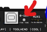
- 0-10V, connected on TH. BUT you need to adjust manually this tension to 5V with a multimeter and the screw here:
This is how I control the speed of the brushless spindel for the CNC.
Or, use GND and PWM on TH only.
It's maybe probably this one actually... ^^ TH respond to a frequency high trigger.
Hope this is helping, let me know.
- GND is G. ok.
- PWM, not in use
- DIR, not in use
- 0-10V, connected on TH. BUT you need to adjust manually this tension to 5V with a multimeter and the screw here:
This is how I control the speed of the brushless spindel for the CNC.
Or, use GND and PWM on TH only.
It's maybe probably this one actually... ^^ TH respond to a frequency high trigger.
Hope this is helping, let me know.
aaron....@gmail.com
Jan 12, 2021, 9:00:58 AM1/12/21
to lasersaur
HI Nicholas
Thanks for getting back to me. As you suggest I have gone for the simplest connection as in the attached diagram. It is not as good as the lasersaur as I can only run the extent function when the door is closed so it is quite difficult to position a work piece accurately. Can you think of a simple solution for this?
I have started using LaserWeb software which is good, but I do miss the lasersaur GUI.
Thanks again
Reply all
Reply to author
Forward
0 new messages