Smooth Slow Sloping Surfaces: Test by Rotating Slice Direction from Z to Y

funBart


lonesock (Jonathan)

PenskeGuy
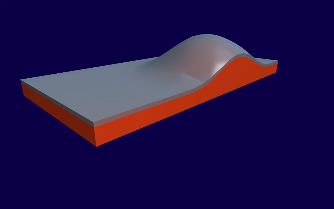
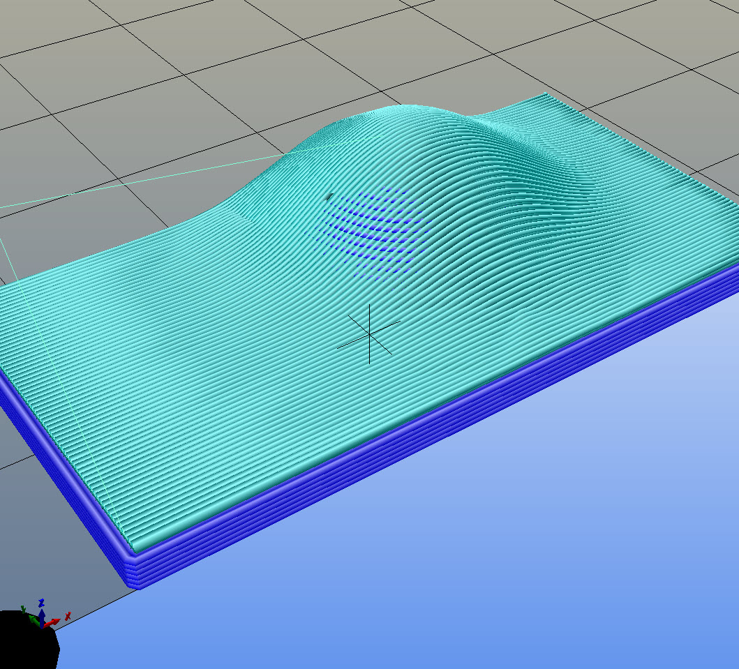
So I wondered how difficult it was to print a skin for slow sloping surfaces with a dynamical Z and X axis, and the Y ax behaving as "staged slices". It turned out surprisingly simple, even printing ok at first try.
OK, I gotta try this, as we have a project that this would benefit from. Any process details that we should look out for? How'd you swap the axes in the skin g-code? What was the method of lining up the two sections?
funBart
- about swapping the axis in the Gcode: generate the Gcode of the skin-mesh, open it in a texteditor, chop-off the start and endGcode, do a search and replace of all Z by Q, then all Y by Z, finally Q by Y.resulting in swapping Y and Z (of course the same can be done when wanting the X swapped with Z).
- The resulting skin-Gcode can be copy pasted after the "base gcode" , but before the endGcode. I have put between the two Gcodes an extra G1 Z50 F900 command, to be sure that the head will be lifted before it's starting to print the "Y slices" as one can't predict it will traveling through already printed (base) parts.
- the most fuzzy part is to make the skin-Gcode fitting the base-Gcode regarding it's position. As Y will be the future Z, you have to be sure only positive values are generated for Y values for the skin-Gcode. You even have to be sure the minimum Y value equals the future starting Z value. So, for my example: the lowest part of the skin has to be known (you get that value out your modeler). I knew that was 2mm for my example. As I printed the skin with 0.3mm layer height and 0.3mm pathwidth (as this values will be Y-Z swapped as well) the height I wanted the skin to begin to print was about 2.3mm. I placed the model on the KS build plate a little shifted upwards (as my bed center is defined as 0,0, and not a corner) generated Gcode and checked it: the lowest Y value was something like 10mm, and I adjusted that by changing the Y value of the Bed center on the Printer//hardware tab, with -7.5mm. Generated Gcode again and checked it was indeed about 2.3mm as lowest Y value. The Gcode of the skin layer is ready after this, as it's at the correct height. (after swapping Y-Z as mentioned above)
- To fit the base Gcode 'under' the now ready skin-Gcode you repeat about the same generating of Gcode. As it's for this simple test I adjusted that XY position by trial and error and checking the position by loading the two (or already combined) Gcodes into Repetier Host. I simply counted in Repetier how many extrusions were misaligned and adjusted that values with the Bed center values of the base model to generate a correct XY position.

Matej Rozman
Jonathan, 5-axis head is not big problem at least not mechanically, post processing and collision detecting is bigger one. Conclusions derived from working with multiaxis CAM for milling.
Great find Bart, will be keeping my eye into this one.
Dne 27. jul. 2014 02:13 je oseba "lonesock (Jonathan)" <lone...@gmail.com> napisala:
>
> Awesome!
>
> I was just talking about a this concept with a friend about 2 hours ago! There would be angle limitations, of course, unless somebody makes a 5-axis 3D printer head?
>
> Jonathan
>
> --
> You received this message because you are subscribed to the Google Groups "Kisslicer Refugee Camp" group.
> To unsubscribe from this group and stop receiving emails from it, send an email to kisslicer-refugee...@googlegroups.com.
> To post to this group, send email to kisslicer-r...@googlegroups.com.
> Visit this group at http://groups.google.com/group/kisslicer-refugee-camp.
> To view this discussion on the web visit https://groups.google.com/d/msgid/kisslicer-refugee-camp/067cd93d-e95d-47b4-a61d-30ea9eb255b5%40googlegroups.com.
>
> For more options, visit https://groups.google.com/d/optout.
funBart
My modeler isn't capable to do a offset perpendicular on each part of the surface, that would result in a skin of 0.5mm everywhere. This should be convenient as Kisslicer would generate a more perfect path.
PenskeGuy
BTW: for that skin I simply ofsetted the shape in Z direction. That's not resulting in a slab of 0.5mm thick everywhere. (only on the flat parts).
My modeler isn't capable to do a offset perpendicular on each part of the surface, that would result in a skin of 0.5mm everywhere. This should be convenient as Kisslicer would generate a more perfect path.Is someone aware of a modeler that can do create a skin, equal thick measured on each perpendicular face?
PenskeGuy
@ Jonathan: so, lets get this thingy into Kisslicer! You only have to make an option to slice in X or Y direction for specific meshes. How hard can it be? Can I expect that Beta tomorrow?
At least as easy as the other "should be simple" addition requests. :)
@ PenskeGuy:
The above sounds complex maybe, but it would have been dead simple when showing the workflow to you live on a monitor...
Got it. Just have to edit the above in my text editor to be certain that I have original X, Y, Z and fX, fY, fZ straight, so I don't get messed up. That's a bit of flipping around. Makes sense when I read it in sequence but, when I come back to it for a reality check, it'll save time if they're separated from each other with new labels.
We do a number of low angle top surfaces and the terracing is an issue sometimes. Forcing the entire model to be printed at a thin layer value gobbles up time in the lower layers. One glass mold we just produced had this issue and I circumvented it by printing the layers below the top as a separate part; low rez. The top surface still had terracing, obviously, as the angle was so low in places. Using this Z/X method; gone. That which saves the situation is that the glass has such a high surface tension that it doesn't conform to the steps if they're small enough; instead performing its own smoothing algorithm.
A different approach, that wouldn't be quite as smooth but could solve a lot of mainstream issues, would be to be able to specify an overall thin layer thickness for a part and impose a Z limit on a thicker layer section that is below it. Above the Z limit, the thin layers would take over. This would have the potential for flow problems, as one usually has different material settings for high and low flow conditions. Switching in mid stream might raise an issue, unless the material could be switched at the time of layer thickness change; preferably on the fly, as it would be the same stock, just different temperature and speeds.
If the Z/X method can be implemented, the above is moot.

Davide Ardizzoia
my nose is bleeding... great code hack!
BUT I believe there are plenty of things Jonathan should polish before looking at this matter (that is useful for a small portion of the audience).
My 0.02E, anyway.
Best Regards from the (extremely) rainy Italy,
Davide Ardizzoia
funBart
Davide Ardizzoia
:-)
Chapeau...
Davide Ardizzoia

lucas...@hotmail.com

Lawrence LaRocque

Joris
Just chimed in because funBart made a post on the umgooglegroup.
You don't need an extra axis. When the angle is more, then the steps are less visible with the regular way of slicing. ..
Btw I could use this very well for the names on top of the elephant. (See www.stapvandeolifantaf.nl)
Cheers \ Joris