chinese '100W' amplifier problem
8,157 views
Skip to first unread message

Bob Edwards
Mar 24, 2021, 12:54:23 PM3/24/21
to Hermes-Lite
I (foolishly?) bought a cheapo HF linear kit off ebay to boost my HL2 5W output. It's the one that uses the dual mosfet MRF9120 device in a white ceramic package. I'm trying to set up the bias, but the amp starts to oscillate past about 300mA. 1A quiescent current is the goal - I believe. Has anyone had the same thing and did you manage to calm it down?
Cheers, Bob G4BBY

WA2EUJ
Mar 24, 2021, 3:58:57 PM3/24/21
to Hermes-Lite
Hi Bob,
Try terminating the input and output when you set the bias. If that doesn't stop the problem (or you already though of it), can you tell the approximate frequency that is oscillating? If it's out of band there could be a way to decrease the gain at that frequency.
73,
Jim WA2EUJ
Bob Edwards
Mar 24, 2021, 7:06:27 PM3/24/21
to Hermes-Lite
Hi Jim,
I had terminated both ends, thanks. The oscillation doesn't show up on my 100MHz scope but, on the advice of a pal who had similar symptoms, I temporarily fitted an AC coupled fast diode detector to each drain. The output measured 65V DC, indicating VHF or UHF oscillation present. Also, when I apply bias and the current goes uncontrollably high, after I remove that bias the current stays high. Only removal of power will lower the current again. Another symptom of parasitic oscillation, I believe. So I was hoping someone had a stabilising dodge for this kit.
Bob Edwards
Mar 24, 2021, 7:08:16 PM3/24/21
to Hermes-Lite
I also disconnected and bypassed the output lowpass filter in case that was a factor. No change.

Michael Durkin
Mar 24, 2021, 8:01:53 PM3/24/21
to herme...@googlegroups.com
Which kit?
The MiniPA100w kit that I bought does not Exhibit this problem ... I bought mine to be used with an FT817.
--
You received this message because you are subscribed to the Google Groups "Hermes-Lite" group.
To unsubscribe from this group and stop receiving emails from it, send an email to hermes-lite...@googlegroups.com.
To view this discussion on the web visit https://groups.google.com/d/msgid/hermes-lite/a65547d7-d6d1-4dbc-8f57-6f3c9dd23be7n%40googlegroups.com.
WA2EUJ
Mar 24, 2021, 8:07:18 PM3/24/21
to Hermes-Lite
Hi Bob,
Is there a schematic online? Is there any feedback? we might be able to reduce the high frequency gain by adjusting the feedback circuit. In many cases a bit of series gate inductance will help but is generally harder to realize.
Jim.
Bob Edwards
Mar 25, 2021, 6:40:09 AM3/25/21
to Hermes-Lite
Here's some pictures of the internals. The switch is just in line with the ptt. The LED is red for power, goes yellow on transmit. As I've said, the PA takes off with and without the LPF board in circuit.
WA2EUJ
Mar 25, 2021, 7:07:39 AM3/25/21
to Hermes-Lite
Hi Bob,
Looks like a very nice integration. If I zoom in real closely it looks like the amplifier is mounted to a black anodized heatsink. That maybe the root cause of why your amplifier oscillates and other who have built the MiniPA haven't had the same problem. The issue is grounding. An anodized surface doesn't conduct electricity very well and presumably, you put some heatsink compound on the mounting surface of the MOSFET, which is also a poor conductor. I think if you used an unfinished heatsink or added a copper heat spreader to you existing heatsink, the problem would disappear.
Even if you tried putting some caps across the feedback resistors to reduce the high frequency gain, you might eliminate the oscillation but the poor grounding issues can manifest in other ways; IM distortion and instability in high VSWR situations are likely.
73,
Jim WA2EUJ

devon...@gmail.com
Mar 25, 2021, 7:38:51 AM3/25/21
to Hermes-Lite
Have you seen a very similar project Cesc did recently. here
Cesc also modified for bias...
Nigel
G4ZAL
Bob Edwards
Mar 25, 2021, 8:44:48 AM3/25/21
to Hermes-Lite
You're right Jim, the heatsink is black anodised, so the pcb and PA transistor are bonded only by their fixings. I've also placed some insulating tape over the tracks underneath. The alternative is to trust the mask as an insulator and use a bare metal heatsink. Still the 0V areas of copper only touch the heatsink if you're lucky - the only for-sure bonds are still at the corners. I will consider that seriously however.
I had tried some solder tags on the PA transistor across to the 0V on the top layer - no change.
Bob Edwards
Mar 25, 2021, 9:20:50 AM3/25/21
to Hermes-Lite
Nigel,
Thanks for that link - that's a useful source - I'll check my bias chain has a 100 ohm resistor for the MRF9120. Off out to the workshop now to strip off the underside of the heatsink to bare aluminium + remove the insulation tape.
Michael Durkin
Mar 25, 2021, 9:49:39 AM3/25/21
to herme...@googlegroups.com
I dont remember using any insulation under the board .... you may have inadvertently created capacitance where you don't want it ...
Pluss I think the feedback resistors I used ... I made the leads fairly short
Mike KC7NOA
--
You received this message because you are subscribed to the Google Groups "Hermes-Lite" group.
To unsubscribe from this group and stop receiving emails from it, send an email to hermes-lite...@googlegroups.com.
To view this discussion on the web visit https://groups.google.com/d/msgid/hermes-lite/dee9183e-64a1-4a19-9028-17f417096052n%40googlegroups.com.
Bob Edwards
Mar 25, 2021, 11:40:26 AM3/25/21
to Hermes-Lite
Stripped the anodising, reduced the 3 big resistors to minimum lead length and replaced R7 with 100 ohm (it was 470), Removed all insulation tape, warped the board so as to make the centre touch the heatsink when screwed down. Still no joy - oscillation.
Put a finger on each of the feedback resistors leads (either end worked) - could set bias at 1A. Remove fingers - oscillation. So it needs some damping at VHF and regions north. A pal in the UK has suggested fitting two 1k resistors from each drain to 12V - said it fixed his smaller amplifier from oscillation. Worth a try.
Michael Durkin
Mar 25, 2021, 11:58:26 AM3/25/21
to herme...@googlegroups.com
Here is a picture of mine in progress
Pluss a short video
To view this discussion on the web visit https://groups.google.com/d/msgid/hermes-lite/f4d90d77-b518-44c4-acce-26b7379fc682n%40googlegroups.com.

Cesc Gudayol
Mar 26, 2021, 11:32:40 AM3/26/21
to Hermes-Lite
Hi Bob
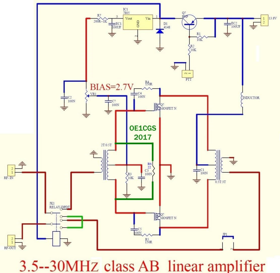
As Nigel pointed out, I did some modifications to the original PA board that are described in my GitHub (https://github.com/ea3igt/HL2-PA70/) In particular I changed the R7 to a 47 Ohms value and added an R6 (20 Ohms) as you can see in the attached schematic. My bias is as high as 4'4 Volt (the consumption with no input is around 4'5 Amp). This is the bias point where the behavior of the PA is more linear (I mean less distortion).
I hope it helps.
Cesc EA3IGT

Prabir Debnath
Mar 27, 2021, 12:43:09 AM3/27/21
to Bob Edwards, Hermes-Lite
Hello Bob,
I encountered with similar problem while building a VHF amplifier with RD70.
I resolved by stabilising the bias circuit and layout too. And later on a pull up HIGH value resistor with the Gnd rail.
Further the connection from the Gate to the PCB trace has been cut and connected back to the PCB through a small coax cable. Possibly doesn't make much sense but that's how it has been stabilised otherwise it was crazy the gate was oscillating.
73
Probir VU2BQF
On Wed, 24 Mar, 2021, 10:24 PM Bob Edwards, <bob.wed...@gmail.com> wrote:
I (foolishly?) bought a cheapo HF linear kit off ebay to boost my HL2 5W output. It's the one that uses the dual mosfet MRF9120 device in a white ceramic package. I'm trying to set up the bias, but the amp starts to oscillate past about 300mA. 1A quiescent current is the goal - I believe. Has anyone had the same thing and did you manage to calm it down?Cheers, Bob G4BBY
--
You received this message because you are subscribed to the Google Groups "Hermes-Lite" group.
To unsubscribe from this group and stop receiving emails from it, send an email to hermes-lite...@googlegroups.com.
To view this discussion on the web visit https://groups.google.com/d/msgid/hermes-lite/aa56128f-b6e8-4cff-a209-91deac7a4167n%40googlegroups.com.
Prabir Debnath
Mar 27, 2021, 12:47:00 AM3/27/21
to Bob Edwards, Hermes-Lite
Oh that's pretty similar issue at my end.
I will strongly recommend to tinker the pull resistor value with the GND.
Even the gate bias is removed the Mosfet will be in conduction mode. I simply terminated with a high value R with Gnd
73
Probir VU2BQF
--
You received this message because you are subscribed to the Google Groups "Hermes-Lite" group.
To unsubscribe from this group and stop receiving emails from it, send an email to hermes-lite...@googlegroups.com.
To view this discussion on the web visit https://groups.google.com/d/msgid/hermes-lite/3603f91d-cdcc-42b4-aa42-f8805acfac90n%40googlegroups.com.
Bob Edwards
Mar 27, 2021, 5:01:54 PM3/27/21
to Hermes-Lite
Probir, thanks for the hints. I'll check out the gate biassing and 'pulldown' resistor.

didier....@gmail.com
Apr 3, 2021, 3:56:41 AM4/3/21
to Hermes-Lite
Hello,
I bought 2 of them as a kit since they are very cheap. Initially i used the MOSFET MRF9120 provided with one of the kit . The tuning and bias setup was terrible and was never able to achieve a correct setup. Even without biasing the Transistor was auto-oscillating.
I suspect the transistor provided is not genuine and did not spent time and energy with this setup.
The good thing is the design andf PCB provided can accomodate IRF510 or IRF530 MOSFET and decided to spend more time replacing the MRF9120 with first a IRF510 which was not so bad when feeding it with 28vdc.
The best result i manage to achieve is with IRF530 and with very minor adjustment i manage to obtain a very decent and reliable result.
You can find more details here :
I use the amplifier for almost 2 years now with about 20 up to 25w digital modes and about 40w SSB and CW
Regarding the LPF since i am using this Amplifier with other low power TRX i choose for automation VK5TM solution and the LPF automatic swithing is provided by RF input detection. I am not using I2C to control the LPF.
To monitor the amplifier i am using an Arduino system to control the Biasing in case of high SWR, High Current or high temperature.
Hope it helps
73s Didier
WA2EUJ
Apr 3, 2021, 11:21:05 AM4/3/21
to Hermes-Lite
I just have to point out that anyone considering the low cost '100W' Ebay amplifier route should really consider the RF Power Tools 100W MRF101 amp. The MRF9120 is discontinued and the units that come with the cheap kits are counterfeit. The amplifiers are prone to instability, intolerant to high SWR, and the gain is much greater on the lower bands than the upper bands. The MRF101 amp uses a brand new RF LDMOS FET that is stable and has flat gain to 10M and is useful on 6M. The amp is about 1/4 the size of the cheap 100W amps and is about twice as efficient and it actually makes 100W. With a standard CPU cooler, you can run 100W @ 100% duty cycle. It might cost a little more if you order all of the parts from Mouser but it will save you a lot of grief in the long run.
Jim.
Bob Edwards
Apr 3, 2021, 11:54:38 AM4/3/21
to Hermes-Lite
Didier,
Thanks for that useful information from your experience. I have purchased a couple of genuine MRF9120 to see if they are more stable than the one supplied. I also bought very cheaply a couple of the 70w kits, so if all else fails will go that route - 40-50w would suit me fine. I found I already have six IRF530 in my parts bin, so plenty of spares if I am careless.
Jim,
The MRF101 amplifier looks very good and I'll be making one of those soon. Definitely the way forward, together with even higher power from the other popular types. For use whist campervanning, I wanted something to run from 13.8v, so was tempted by the dark side - so many of these 100w kits for sale, what could go wrong? ;-)
Good advice, both, thank you again, Bob g4bby
Bob Edwards
Apr 5, 2021, 6:50:30 AM4/5/21
to Hermes-Lite
I built up another minipa pcb with an MRF9120 from a U.S. source (wasn't expensive, confirmed it to be genuine part). The gate bias could be set so as to demand 1A quiescent from the 12V supply with no signs of instability. The only peculiarity with this new transistor was that 5.3V gate bias was needed, so I had to change the 5V regulator for an 8V one. I'm now looking forward to commissioning it with the Hermes Lite and dummy load. It does throw doubt on the used transistor supplied with the original kit.
This has been a very useful thread for me, as there isn't a lot of useful data written about these cheapy amplifiers, other than Didier's web site above.
WA2EUJ
Apr 5, 2021, 5:46:01 PM4/5/21
to Hermes-Lite
Motorola issued "product discontinuance 8841" on May 1, 2003 saying that the last available date to order a MRF9210 was 31 January 2004. The Freescale/NXP, MRF9210R3 is listed as 'discontinued' and the datasheet is stamped 'archived'. Even if the units on Ebay have the Motorola symbol on them I don't see how they could be real Motorola MOSFETs. Where have they been for the last 17 years? and how did they get to China? I don't see any NXP branded parts available for sale.
I'm not trying to be a Debbie-Downer but I've spent a lot of money on 'real' VRF2933's and even from the same supplier in the same batch, some work, some don't and some aren't even MOSFETs, they are bipolar transistors of some sort. Quality control is poor and customer service/replacement/refund is non existent.
The Vgs-on should be 1.5 - 4V so if you need 5.3V that's a sure sign that the internal structure is different from a MRF9210. I'm also doubtful of a circuit that can accommodate either a IFR 530 with a Ciss of 1000 pF or the MRF9210 with ten times less input capacitance, one of them is bound to oscillate and/or have a terrible input SWR.
Jim.
devon...@gmail.com
Apr 6, 2021, 9:07:42 AM4/6/21
to Hermes-Lite
I have just today received two Motorola MRF9120 that I bought from a China re-seller of 'used/reclaimed parts'.
The logo looks genuine and the parts are definitely used as there is solder on them and the location 'lugs' have evidence of a screw having been tightened up on them.
I have the miniPA kit, but with the 2x unknown FET's and will build it with a single MRF9120.
If it goes zzztttPOP - I'll let you know !!
Usually, counterfeit parts have look-alike logos, but not quite right to the real thing, Well, that's what I'm hoping here!
Nigel
Bob Edwards
Apr 6, 2021, 1:59:59 PM4/6/21
to Hermes-Lite
The MRF9120s I bought seemed to bias up ok, but did not amplify, bearing out Jim's warnings above. When the weather warms up again and so does the garage workshop, I'm going to refit with some IRF530s I've had around for ages and shut the lid on this.
Bob Edwards
Apr 6, 2021, 2:05:48 PM4/6/21
to Hermes-Lite
There must be many people with these minpa pcbs lying around discarded for want of a decent alternative to the original transistors. Has anyone used a pair of more modern RF devices with this pcb?

Simon
Apr 6, 2021, 3:56:24 PM4/6/21
to Bob Edwards, Hermes-Lite
Mrf300 a and b’s ( if memory serves me.)
600w out for little outlay.. last looked circa £30 each..ok need a good lpf..or run at 12v for 100w out..
I made my own little pa..uses a pair of mrf151’s ..so good for 300w. But run them at 13.8v..circa 80w out..indestructible at 13.8v.
Simon g0zen
On 6 Apr 2021, at 19:05, Bob Edwards <bob.wed...@gmail.com> wrote:
There must be many people with these minpa pcbs lying around discarded for want of a decent alternative to the original transistors. Has anyone used a pair of more modern RF devices with this pcb?
--
You received this message because you are subscribed to the Google Groups "Hermes-Lite" group.
To unsubscribe from this group and stop receiving emails from it, send an email to hermes-lite...@googlegroups.com.
To view this discussion on the web visit https://groups.google.com/d/msgid/hermes-lite/b6ac614b-7486-417f-9a2f-e67e74dc6808n%40googlegroups.com.
didier....@gmail.com
Apr 6, 2021, 5:01:27 PM4/6/21
to Hermes-Lite
Hello,
According Jim statment regarding the MRF9120, i agree and the kit i bought with this transistor is suspicious. For myself i did realize very quickly the transistor was totally unstable . I cannot remember the biasing i had tested but for sure i cannot achieve something stable.
My assumptions with Bob initial post , i guess he bought the same kit i have and since all the kits sold on internet and alliexpress seems to have the same design and use the same components value. Using a IRF530 is maybe something he can test.
When i decided to move with the IRF530 , i did not have major issues and the modification i made against the initial design are providing nowadays a very stable tiny amplifier obviously very far in terms of output power compare to MRF300 (i prefer to use tube/valve for QRO output power , this is a personal choice). Currently the SWR from this amplifier input and output is really good and i use this amplifier roughly with a maximum of 30watts output power and this is mostly what i was targetting. Above the amplifier spectral purity i not acceptable in my point of view .
As far i can remember some guys manage to obtain some good results using a MRF186 with the PCB from the kit.
73s Didier
Simon
Apr 6, 2021, 6:43:33 PM4/6/21
to didier....@gmail.com, Hermes-Lite
Hi Didier
Yes i like valves for qro too..i only use homebrew.
See below ( 1.5kw using soviet triodes. Such a bargain..£30 for 1500w tubes!)

However a nice little mosfet or ldmos amp for the hl2 etc is very useful.( one shown uses the parts bin mfr151’s but st 13.8v.

Simon g0zen
On 6 Apr 2021, at 22:01, didier....@gmail.com <didier....@gmail.com> wrote:
Hello,
To view this discussion on the web visit https://groups.google.com/d/msgid/hermes-lite/d6310da0-54a2-4455-9cb4-ebcfa9c66f7an%40googlegroups.com.

Heath Petty
Apr 7, 2021, 12:29:31 AM4/7/21
to Hermes-Lite
I have been following this thread with great interest as I have one of these kits and am looking to build it up to use with the Hermes when at home. There is lots of great info on this thread, but I am completely new to working with amps. Is there a primer somewhere that could help me understand how to adjust or test the amp once I get it built? I have a DMM, nanovna, an SWR meter, and a dummy load. I am planning on following Cesc's mods. I would also like to see about making it more compact for possible portable operation from my camping trailer. For example how do I measure/adjust the bias (found videos explaining what the bias is, but not sure how to measure it)? What other gotchas do I need to look out for? If anyone has some good links or YT video I am happy to dive and learn :).
I also am thinking of buying the MRF101 amp boards and parts, then using a 48v electric bike battery to power it in the field (with a 12v step down transformer for the Hermes). Of course this is all for the next few years until the solar cycle really kicks into gear :)
Thanks,
Heath
didier....@gmail.com
Apr 7, 2021, 2:14:30 AM4/7/21
to Hermes-Lite
Hello ,

.jpg?part=0.2&view=1)
Whouah !!! your tube amplifier is a beauty . Myself i am using pentode tube for my amplifiers but my power i only about 300 up to 600/700w but the Plate/anode voltage is only about 1000v. i manage to find on ebay a great seller in Ukraine and i manage to grab some 6P45c/6п45c (Equivalent to EL519) for 16USD and surprisingly they work very well also for digital modes especially PSK31/RTTY the modes i am using a lot. i am refurbishing and modifying a 30 years old citizen band amplifier using also EL519 and i am very happy with the results (more details here : https://f5npv.wordpress.com/el519-hf-amplifier/ )
With this one above with the Hermes Lite i manage to have about 170w output and the following one is about 300w (I am still implementing and finalizing the biasing)
To comeback with Amplifier for the Hermes lite i think LDMOS transistors remain a great choice since they can provide also a great output with only a tiny input. In addition compare to a IRF510 or IRF530 they are more stable (Bear in minds IRF530 are not the best performer for RF amplification since this kind of transistor is not dedicated for RF amplification). The MRF101 kit looks really nice and if you are looking for something portable this is a winner for sure.
The biasing setup is :
-First you need to check the datasheet of your Mosfet or LDMOS Transistor in order to check the biasing voltage and current magnitude your transistor will need
-You will need a lab power supply with current (Amp) reading and limitation
-a wattmeter
-a dummy load
-A Tinysa or any spectrum analyzer with a RF coupler is highly recommended
-a multimeter
-Setup the biasing voltage to the minimum a check with the multimer
-powerup the amplifier which is plug to your Hermes lite and the dummy load and check to current to ensure the current provided is not too high. The power supply current limitation must be setup according the range of your amplification.
-switch on the amplifier without applying power from the Hermes lite and check to current with your Lab power supply. Note this current and ensure there is no output power and excessive current . If they is some power or current : something wrong !!
-If all good , Key down the PTT without any power from the hermes lite and start to increase the biasing voltage . You should notice an increase of the current on the Power supply current reading and for example if your transistor need 3 to 5vdc with 100ma current , setup the biasing in between (about 4v with and 50ma) . If the overall current is not to high , and you notice no output power on your wattmeter , you are good. If not check your amplifier.
-If all good you can apply some little power and start to fine tune the biasing . During the fine tuning , you need to check the spectrum analyzer and ensure there is no oscillation and a clean spectrum.
This is roughly how to setup the biasing but you can find on Internet more details tutorials.
73s Didier F5NPV

Duncan Clark
Apr 7, 2021, 3:00:07 PM4/7/21
to herme...@googlegroups.com
In message <069BC4CF-7D64-42CF...@gmail.com>, Simon
writes
http://www.cqham.ru/HiFi_Contester_EX8A.htm
Google translate does a reasonable job.
Duncan
--
Duncan Clark
G4ELJ
writes
>ee below ( 1.5kw using soviet triodes. Such a bargain..£30 for 1500w
>tubes!)
Or Pentode GU-81M:
>tubes!)
http://www.cqham.ru/HiFi_Contester_EX8A.htm
Google translate does a reasonable job.
Duncan
--
Duncan Clark
G4ELJ
Simon
Apr 7, 2021, 5:02:05 PM4/7/21
to Duncan Clark, herme...@googlegroups.com
Hi Duncan
Yes seen these tubes..
Just soo big..only thing that has put me off trying one..still silly cheap too..
Get 3 for £100 and i expect they will out live me..
Saying that i have a box of spare nos tubes for my amp..So really i should not bother, as i expect they will also out live me..plus i have a homebrew 1kw plus ldmos amp as standby/ slash can’t wait for tube amp to warm up situation..
As 400w is our limit here I hope the 1.5kw tube amp will out last me on its original tubes anyway ( it loafs along at 400, making oil cooler for them at moment, to keep noise down as shack in front room..( My so wonderful wife complains at noise of fan..fair enough it is LOUD..) plus will allow amp to run 2kw for when we to move to Mars or Moon..
Simon g0zen
Ps..back to 100w hl2 amps..
One can really easy build a bomb proof 13.8v amp using say a pair of mrf151’s or 150’s
As they are rated at 50v , ran at 13.8 they give a good healthy 50plus out dc-150mhz for 2w in..one can sc or oc the output with no issues..run at 16v and 100 plus..
This is my hl2/ elad duo amp shown in earlier pic/post..( silver box.) uses a pair of mrf151’s at 13.8v , homebrew lpf..though would have been cheaper to use ( top tip here!) a lpf from a scrap hf rig..( ebay.)
> On 7 Apr 2021, at 20:00, Duncan Clark <d_cl...@g4elj.me.uk> wrote:
>
> In message <069BC4CF-7D64-42CF...@gmail.com>, Simon writes
> --
> You received this message because you are subscribed to the Google Groups "Hermes-Lite" group.
> To unsubscribe from this group and stop receiving emails from it, send an email to hermes-lite...@googlegroups.com.
> To view this discussion on the web visit https://groups.google.com/d/msgid/hermes-lite/f4GlP2OhDgbgFwCF%40ntlworld.com.
> You received this message because you are subscribed to the Google Groups "Hermes-Lite" group.
> To unsubscribe from this group and stop receiving emails from it, send an email to hermes-lite...@googlegroups.com.
WA2EUJ
Apr 7, 2021, 5:44:59 PM4/7/21
to Hermes-Lite
Hi Heath,
I would recommend buying at least 10 of the devices that you plan to use and build a test fixture and see if you can find two the have the same Vgs for the Idq that you plan to use.
Testing RF amplifiers can be tricky, you need a good power supply with volts and amps readout, high power loads and a decent (low harmonic) RF source. Be prepared to destroy devices, any RF device operating near it's maximum potential is one RF cycle away from destruction at any time. My daughter comes into the house, sniffs and says "Daddy's been testing amplifiers again."
Testing the protection circuity/algorithms is particularly destructive.
73,
Jim WA2EUJ

tmoto...@gmail.com
Apr 7, 2021, 11:04:51 PM4/7/21
to Simon, Duncan Clark, herme...@googlegroups.com
Hi Simon -
Love to hear more about the amp that your use for your HL2 & Duo - I have both also - and looking for a stable build to use with them.
Care you share more about your build?
Thanks,
Tom, K2TC
To view this discussion on the web visit https://groups.google.com/d/msgid/hermes-lite/7466D263-2151-4B92-AFB5-0CF27BAE4DF4%40gmail.com.
Love to hear more about the amp that your use for your HL2 & Duo - I have both also - and looking for a stable build to use with them.
Care you share more about your build?
Thanks,
Tom, K2TC

Robert Dale
Apr 8, 2021, 2:58:17 PM4/8/21
to Hermes-Lite
Hi Simon,
Very nicely done (on both amps)! I would also like to get more info on your 100w build (schematic, board etc...)
Cheers and 73,
Robert VE7ZN
Simon
Apr 8, 2021, 7:26:18 PM4/8/21
to Hermes-Lite
Hi
Will revisit the 100w amp this weekend and post some info..
I made it “ freestyle” ie just made it.
So cant remember exactly what i did.
Will take pics and draw a rough crt dia..but its real easy assuming one can home etch a pcb..
Give me a few days.. decorating home at moment..a job I HATE! Once done Wife will give me time to play radio again..lol
Simon
On 8 Apr 2021, at 19:58, Robert Dale <rober...@gmail.com> wrote:
Hi Simon,
To view this discussion on the web visit https://groups.google.com/d/msgid/hermes-lite/39012ca4-8566-41cf-bd96-cd57c5186396n%40googlegroups.com.

Konstantin Krayz
Jun 24, 2021, 12:04:19 AM6/24/21
to Hermes-Lite
Hey, I dont know if this is still relevant but I found this russian blog https://ua3reo.ru/kv-usilitel-na-mrf9120/ . This guy (ua3reo) solved the oscillating problem by cutting the traces that go to the TO-220 style transistors from the transformers and grounded the source.
73s KD2OIH

Zilvinas LY2SS
Nov 2, 2021, 6:02:25 PM11/2/21
to Hermes-Lite
It might be useful for somebody.
There's a flaw (one of many) in this design - the bypass relay. If you feed the RF signal directly to transformer the instability/oscillation dissapears. (It might be - not confirmed - that on high power the same relay could induce RF voltage to bias circuit).
I don't know a simple cure for it yet (modify existing schematics, or move the relay or even 2 of them outside the board).
And below is the archive with mods made by russian ham (docs inside are in russian language - google translate it):
He's got clean 90 Watts using 22Volts power supply.
The archive in essence is the work done by him an discussed in very loooong thread (~150 pages) about this kit:
73! Zilvis LY2SS
Reply all
Reply to author
Forward
0 new messages