looking for recommendation of an H-bridge module

440 views
Skip to first unread message

Guy Ovadia

unread,
Oct 7, 2012, 8:31:35 PM10/7/12
to has...@googlegroups.com, no...@comet-me.org
Hi,

I'm looking for a DC motor (H-bridge) driver board with the following specs:

- over 3A current (preferably 5A or more so it's not used at max capacity)
- over 24V voltage (again, 28V or more is better)
- looking for a ready to use board, as opposed to a bare chip
- fast availability is a plus (someone selling in Israel, or a fast shipment from abroad).
- I don't want undocumented "who knows what's that chip"-based boards, like the multiple offerings I found on eBay. I want good documentation.

recommendations?

thanks!
Guy.

Yair Reshef

unread,
Oct 8, 2012, 3:35:53 AM10/8/12
to has...@googlegroups.com, no...@comet-me.org
--
yair99@gmail
050-6301212
tlv, israel

Yair Reshef

unread,
Oct 8, 2012, 3:43:00 AM10/8/12
to has...@googlegroups.com, no...@comet-me.org

Udi Finkelstein

unread,
Oct 8, 2012, 4:38:34 PM10/8/12
to has...@googlegroups.com
The cheapest is the widely use L298N based boards.
They are rated up to ~50V, but only 2A for continuous use. However, each board is a dual motor driver, and you can combine 2 channels to drive 1 motor up to 4A.

The major drawback, as I've wrote here in the past, is that this IC is based on a bipolar design, so expect a large heat dissipation.
At 24V/2A for each channel, you can expect 3V to 4V drop on the board itself, which means:
1. You either drive it with 28V and take the risk the drop will be smaller and you may go over the 24V
2. Drive it with a lower voltage and end with less than 24V on your motor.

On the positive side, these boards starts at $5 on ebay (a dual channel that's turned into single channel).

The pololu boards Yair mentioned are great, but much more expensive.
I would take a look at http://www.pololu.com/catalog/product/1451 or http://www.pololu.com/catalog/product/2502
Notice that the dual board is incorrectly specced at 16V, which caught my attention because the single chip version of the same board is specced at 14V.
When you check the actual page you see that the dual motor is at specced at 24V.
If you feel 24V max is too close to your target, you can check http://www.pololu.com/catalog/product/755 at ~$40 (single channel 30V/15A).


Udi


On Mon, Oct 8, 2012 at 2:31 AM, Guy Ovadia <guyov...@gmail.com> wrote:

Guy Ovadia

unread,
Oct 8, 2012, 6:33:59 PM10/8/12
to has...@googlegroups.com
Thanks Udi. I've looked at the pololu stuff and one of these is probably what we'll use. We'll be working with 24V batteries (lead-acid) including during charging, so we can reach almost 30V. This means most of them aren't suitable (some of the pololu driver pages have warnings specifically against this kind of use). however there are some which are OK.

btw any hint of what is the chip on these boards?
http://www.pololu.com/catalog/product/756
(i.e. the 28 pins chip, not the mosfets)

Udi Finkelstein

unread,
Oct 8, 2012, 7:54:10 PM10/8/12
to has...@googlegroups.com
Sorry, not. It seems they deliberately cover it:
http://forum2.pololu.com/viewtopic.php?p=27184&sid=3c388b49927d600403fb01dd12effc8c#p27184

BTW, if you look closely, all single channel VVvAA boards (e.g. 36v9, 25v15, etc.) use the same md07a board with different MOSFETs:
http://forum.pololu.com/viewtopic.php?f=15&t=3250&p=15080&hilit=36v9#p15080
The 26v9 is actually a 18v15 picture.

Udi

Guy Ovadia

unread,
Oct 11, 2012, 8:00:43 AM10/11/12
to has...@googlegroups.com, no...@comet-me.org
ok, found the chip on those modules: Allegro A3941K
http://www.allegromicro.com/en/Products/Motor-Driver-And-Interface-ICs/Brush-DC-Motor-Drivers/A3941.aspx

I think those will do for our purpose.

Udi Finkelstein

unread,
Oct 11, 2012, 8:06:43 AM10/11/12
to has...@googlegroups.com
How did you find out?

Guy Ovadia

unread,
Oct 11, 2012, 8:11:20 AM10/11/12
to has...@googlegroups.com
looked for some catch phrase from their data which isn't just "standard" words. chose "FF1" and "FF2" pin names with their descriptive text. didn't get to the specific IC that way but found out that Allegro tend to use this terminology (perhaps not only them but most of the results were their chips). then I went to their site and looked for relevant chips with 28 pins. that A3941 was the only choice, and after reading the datasheet there were many signs to verify it.

Udi Finkelstein

unread,
Oct 11, 2012, 8:40:50 AM10/11/12
to has...@googlegroups.com
Nice!

One the things that made me raise an eyebrow at first was that I specifically remembered that the center pins on both sides of the IC were wide, like those in power amp ICs.
Upon a closer look at the pololu board I see it's only the PCB contact that's wide. The IC pin themselves are all the same.
http://b.pololu-files.com/picture/0J1024.600.jpg?7cce1365759b4b4f62ea07884b0c3621

Guy Ovadia

unread,
Oct 11, 2012, 8:42:44 AM10/11/12
to has...@googlegroups.com
yes, I went through the same mental process :) if it has wide pins, then it's a power IC of some kind, but why do they use a power amp and then use external fets...?

jr

unread,
Oct 11, 2012, 9:49:03 AM10/11/12
to has...@googlegroups.com
Guy can you pls. tack on 3 more units (4 if the;yre cheap) to your order  - Kfir and I need 6A Hbridge drivers for our 6Nm steppers. I am not sure of max voltage.  What cost have you got to?

I was toying with building my own Hbridges - but imagine the ultimate component cost of 4 hipower mosfets per motor coil and thus 8 per motor, will approach the commercial unit cost

Guy Ovadia

unread,
Oct 11, 2012, 10:24:44 AM10/11/12
to has...@googlegroups.com
nope, I ordered this from Israel and for Comet-ME - anyway there's no sense in combining an order inside IL.

I'd recommend using the highest voltage you can get a good PSU for (48V is reasonably common), since more voltage = faster current waveform risetime = higher possible step rates with some torque remaining = faster motors. find a PSU and choose drivers appropriately.

Moty Marcos Dorfman

unread,
Oct 11, 2012, 11:17:42 AM10/11/12
to has...@googlegroups.com
is this ok?
http://www.ebay.com/itm/480W-High-Power-CNC-Stepper-Servo-Motor-Driver-Switching-Power-Supply-48V10A-PSU-/180976247430?pt=LH_DefaultDomain_0&hash=item2a23066286

remember people im in the usa and leaving back to israel the 29/10

so if you can get something good on ebay i can bring it

this specific psu is 220 v compatible

Guy Ovadia

unread,
Oct 11, 2012, 2:20:28 PM10/11/12
to has...@googlegroups.com

Moty Marcos Dorfman

unread,
Oct 11, 2012, 2:38:20 PM10/11/12
to has...@googlegroups.com
in any case i will have an address for tomorrow

jr

unread,
Oct 15, 2012, 8:18:48 AM10/15/12
to has...@googlegroups.com
I just got an old sample order in , ten units of vishay SI9978 H bridge driver which is designed to drive  4 nmos transistors (somehow nmos is being used also for the high side switches) at up to 40V.
The price of a suitable 40V 60A transistor  being only $3 , it seems that $50 for the 7A motor driver linked below is pretty high (theres also a powersupply in the $50 unit but i don;;t think that soaks up the difference)
Anyway Guy if you can step me thru how to deal with a surface mount driver (how to solder it i mean)  I will try to set up a motor driver or two.

Yuval Adam

unread,
Oct 15, 2012, 8:20:36 AM10/15/12
to has...@googlegroups.com
Perhaps the time is nigh for an SMD soldering workshop?
--
Yuval Adam
http://y3xz.com


Udi Finkelstein

unread,
Oct 15, 2012, 8:40:06 AM10/15/12
to has...@googlegroups.com
Luckily for you, the pads also extends to the side of this package, making them easier to solder.
Do you have a carrier PCB for these?
The PowerPAK-SO8 footprint has a large contact below, probably intended for heat spreading.
http://www.vishay.com/docs/64721/an913.pdf
jr, Do you want to design a PCB yourself? This is ideal for a x10 5cmx5cm PCB order seeedstudio or iteadstudio.

Yair Reshef

unread,
Oct 15, 2012, 8:43:27 AM10/15/12
to has...@googlegroups.com
jr do you have a support circuit diagram for that chip?
 i think to use a generic breakout board for this SOIC package and work on a breadboard. 
before committing to all smd workflow
or this without any soldering

but an smd workshop is def cool.

On Mon, Oct 15, 2012 at 2:20 PM, Yuval Adam <yuv...@gmail.com> wrote:

Udi Finkelstein

unread,
Oct 15, 2012, 9:05:52 AM10/15/12
to has...@googlegroups.com
The problem is not the SI9978. generic SOIC adapters are not a problem.
The problem is with the NMOS jr wants to use. They seem to be designed for excessive heat dissipation, and you probably want to have a board where the 2nd layer uses copper pour.
The large pad is drain connection, so you may want to split the 2nd layer into two halves, one for GND and one for VDD since 2 transistors will have their drain on GND and 2 will have it on VDD.

jr

unread,
Oct 15, 2012, 12:03:06 PM10/15/12
to has...@googlegroups.com
I have a bunch of powermos of various vintages so I will try to use those up first, and try to solder the si9978 or get one of those connector boards yair linked, 
and heatsink the powermos with chunks of aluminum or copper.

the nmos transistor i linked was just an example for a current price - maybe its particularly well suited, I am not sure

If I actually get something successfully working I would love to do a seedstudio or  itead pcb with some standard nmos and proper heat solution as udi suggested 
i know sefi was after a high current stepper driver for one and guy just got some so there seems a bit of demand for this.
What do people use for layout these days? is the 'eagle' still around?

the 9978 hbridge ckt can be seen here.
i need to add the logic going from 'step' and 'direction' standard control signals, to signals for each of two SI9978's (each 9978 is a single H-bridge driver, for 
running a single coil in either direction; the stepmotor has two coils to be run in a certain pattern for turning a stepmotor clockwise or anticlockwise, rather exhaustive explanation  here ). 
I'd also like to add a manual step option so you can test your cnc , robot arm or whatever without needing a pc
nice to have -  optoisolation, microstepping, antiresonance , step/position counter, bitcoin miner


Yair Reshef

unread,
Oct 15, 2012, 12:08:42 PM10/15/12
to has...@googlegroups.com
i have a few of those soic to dip boards. ill bring one to the space

Udi Finkelstein

unread,
Oct 15, 2012, 1:11:09 PM10/15/12
to has...@googlegroups.com
1. I was about to ask if you have a SOIC adapter (50mil spacing), but Yair already replied.
Yair - please check if yours are for the 50mil spacing, wide SOIC variant.

2. I have to confess I haven't made any PCB yet (at least in the last 15 years, older stuff done with OrCAD on DOS doesn't count), but I have both Eagle 6 and KiCAD installed, although Eagle now has an open, XML-based file format, I'm still trying to go the KiCAD path first if not for the fact that it is not size limited, and mastering it would be better in the long run.

3. I have 2 examples of (the same) 50mil SOIC pattern protoboard that coexists with DIP! I've seen this in two boards, both are very old (10-20 years old), yet I haven't see this pattern ever used before.
I would like to re-do it in either KiCAD or Eagle.
https://picasaweb.google.com/udi.finkelstein/PCB?authkey=Gv1sRgCLnuvPO5u6SKqAE
I think this kind of protoboard makes the generic 100mil grid useless.

Udi

Yair Reshef

unread,
Oct 15, 2012, 3:19:23 PM10/15/12
to has...@googlegroups.com
ok, its these two,
Universal SMD PCB Board : S Series 06
Universal SMD PCB Board : SOIC to DIP Adapters
http://stores.ebay.com/Warf-Electronics-shopping/Universal-PCBs

warf is actually i good thai online store

On Mon, Oct 15, 2012 at 9:15 PM, Yair Reshef <yai...@gmail.com> wrote:
>
> its kinda nice the set i have, i dont know where i bought it from.
> it has all kinds , 50mm included
> http://i.imgur.com/VBMGO.jpg
>
>
> On Mon, Oct 15, 2012 at 7:11 PM, Udi Finkelstein <udi.fin...@gmail.com> wrote:
>>
>> 1. I was about to ask if you have a SOIC adapter (50mil spacing), but Yair already replied.
>> Yair - please check if yours are for the 50mil spacing, wide SOIC variant.
>>
>> 2. I have to confess I haven't made any PCB yet (at least in the last 15 years, older stuff done with OrCAD on DOS doesn't count), but I have both Eagle 6 and KiCAD installed, although Eagle now has an open, XML-based file format, I'm still trying to go the KiCAD path first if not for the fact that it is not size limited, and mastering it would be better in the long run.
>>
>> 3. I have 2 examples of (the same) 50mil SOIC pattern protoboard that coexists with DIP! I've seen this in two boards, both are very old (10-20 years old), yet I haven't see this pattern ever used before.
>> I would like to re-do it in either KiCAD or Eagle.
>> https://picasaweb.google.com/udi.finkelstein/PCB?authkey=Gv1sRgCLnuvPO5u6SKqAE
>> I think this kind of protoboard makes the generic 100mil grid useless.
>>
>> Udi
>>
>> On Mon, Oct 15, 2012 at 6:03 PM, jr <jeremy...@gmail.com> wrote:
>>>
>>> I have a bunch of powermos of various vintages so I will try to use those up first, and try to solder the si9978 or get one of those connector boards yair linked,
>>> and heatsink the powermos with chunks of aluminum or copper.
>>>
>>> the nmos transistor i linked was just an example for a current price - maybe its particularly well suited, I am not sure
>>>
>>> If I actually get something successfully working I would love to do a seedstudio or itead pcb with some standard nmos and proper heat solution as udi suggested
>>> i know sefi was after a high current stepper driver for one and guy just got some so there seems a bit of demand for this.
>>> What do people use for layout these days? is the 'eagle' still around?
>>>
>>> the 9978 hbridge ckt can be seen here.
>>> i need to add the logic going from 'step' and 'direction' standard control signals, to signals for each of two SI9978's (each 9978 is a single H-bridge driver, for
>>> running a single coil in either direction; the stepmotor has two coils to be run in a certain pattern for turning a stepmotor clockwise or anticlockwise, rather exhaustive explanation here ).
>>> I'd also like to add a manual step option so you can test your cnc , robot arm or whatever without needing a pc
>>> nice to have - optoisolation, microstepping, antiresonance , step/position counter, bitcoin miner
>>>
>>>
>>>
>>>

Yair Reshef

unread,
Oct 15, 2012, 3:15:11 PM10/15/12
to has...@googlegroups.com
its kinda nice the set i have, i dont know where i bought it from. 
it has all kinds , 50mm included

jr

unread,
Nov 4, 2012, 5:44:37 AM11/4/12
to has...@googlegroups.com, no...@comet-me.org
attached: a ckt to take step+direction signals from parallel port (as output by mach3 and linuxcnc) 
and convert them to enable/direction signals on 2 si9978 Hbridge drivers

i blv i have included all info required for an intelligent entity knowing nothing abt this to check if my ckt is ok
step.pdf
step.docx

jr

unread,
Nov 5, 2012, 12:45:18 AM11/5/12
to has...@googlegroups.com, no...@comet-me.org
I think the sequence implemented by the xor ckt is the top left one namely
terminal 1a + + - - +
terminal 1b - - + + -
terminal 2a - + + - -
terminal 2b + - - + +
and thus the coils are always on - so i don't need to worry about turning the si9978 'enable' pin on or off, its always on.
Thus the xorcircuit can directly connect to the si9978 , with the x1 and x2 pins driving the 'dir' pins of the two si9978's.
Since i dont use the Y1,Y2 signals it would be possible to use a ckt that directly generates the 'direction' sequence namely
dir1 1 1 0 0 1 1 0 0
dir2 0 1 1 0 0 1 1 0

but it seems since there are 4 states the device needs 2 bits memory and thus the 2 flipflops are required.  maybe its poss. to kill off
an xor or 2.
step2.pdf

jr

unread,
Nov 6, 2012, 5:30:07 AM11/6/12
to has...@googlegroups.com, no...@comet-me.org
we now have come to the point of needing a high-power dc supply for our motor drivers :
60-100VDC and 20 amps.
We can either 1. roll our own  or 2. attempt to revive some UPS devices that Moti donated.

1. In a simple approach, this requires a rather big xformer of N=~3 , rectifier, smoothing caps, and possibly regulator (personally i think active regulation unecessary for this app). 
I got five 100V 10000uF caps which would provide sufficient smoothing (go here and do 'run-time domain sim' to see V vs. t)
Wer'e waiting on a few places for an xformer. We could in principle  even roll our own (toroid) transformer since we have access to ~3mm diam magnet wire and apparently can use iron powder+epoxy core. 
This would be pretty cool but is yet another 'left turn' on our circuitous route to getting our cnc running.
The complex approach would be to try to build a switching ps but this is way beyond my ability.

2. the ups's (we have 2) are Tensor (T100 iirc) 3kW devices with 72VDC battery bank.  We can theoretically use the 72VDC banks to run our system (assuming they are being continuously replenished at 3kW); the batteries were removed to allow the things to be moved by human beings, thus we attempted to fake their existence using one of the 100V 10000uF caps. 
This didn't work; we got no volts on the cap, no powerlights.  So we can try again using 8 nine-volt batteries instead of the normal 6 twelve-volt, 10Ah batts.
My hope is that the different Ah values will not matter; maybe the cap was so low however that in that case is did matter. or maybe the system
wants to see 72V before it starts charging the batts.  This is all assuming the things still work.

jr

unread,
Nov 6, 2012, 5:27:30 PM11/6/12
to has...@googlegroups.com, no...@comet-me.org
does anyone recognize the circled elements in the diagram attached...calling udi...calling guy....
wtf.jpg

jr

unread,
Nov 6, 2012, 5:30:55 PM11/6/12
to has...@googlegroups.com, no...@comet-me.org
i mean these circled thingies
wtf.jpg

Guy Ovadia

unread,
Nov 6, 2012, 5:43:54 PM11/6/12
to has...@googlegroups.com
it's nothing, it just represents the pins of the package... not the best way to draw this, IMO. I think it means that the drain of that FET has two pins in this package, which are internally connected (to support a higher current).

jr

unread,
Nov 6, 2012, 6:06:09 PM11/6/12
to has...@googlegroups.com
ok good...btw on the datasheet it says the high side gate drive max is 17V , but the supply voltage can be 40V - how does it manage to run the high side mosfets i wonder? dont the gates 
have to be higher than the sources by like 5V or so?  does only 17V-5V get put across the load?

in any case we were wanting to drive our motors with up to 80V, I guess we have to find another hbridge driver?

jr

unread,
Nov 8, 2012, 5:21:48 AM11/8/12
to has...@googlegroups.com
In case this was keeping you up at night: 

a transformer core permeability does not directly determine the output voltage (rather the voltage is determined by coil ratio N1/N2) for the following reason :
It is the B-field (mag. flux density) that is directly created by a current ; the H field (magnetic field strength) results from the B field and the local permeability.
The voltage induced in secondary is dependent on B and so the permeability doesn't enter.
I guess you could look at it another way, that the primary determines H and the secondary voltage 'reads' H , also avoiding dependence on permeability.
But I think it is more intuitive to think that B is the 'fundamental' thing here while H is dependent on B and the mu of a particular situation.

thats all from this physics forum  which is pretty good

Kfir B.

unread,
Nov 9, 2012, 3:19:09 PM11/9/12
to has...@googlegroups.com
it was keeping me up at night thanks :) 
BTW look at your inbox!

jr

unread,
Nov 12, 2012, 2:49:39 AM11/12/12
to has...@googlegroups.com
Moti your 3kW ups works like a champ as a 72V dc source - when connected to enough 12V batts, it sourced 0.5Adc continuously no prob. (trying to draw 7A killed the weak batteries so fast that the unit went into a panic mode). As soon as the ups is pulled off the batts, the 0.5A drains the voltage down rapidly, proving it was the ups and not the batts that were driving the car.
This is all due to Frank's help - that guy is a treasure
I will price 6x12V 1A lead acids today - if they are too dear then I was thinking 8x9V batts.
Frank opined that since these 9V alkalines are not meant to be charged, they will not survive this (ab)use.
What if I used rechargeable 9V batts? Or a small isolation xformer off the mains giving 72V , feeding a cap?  

Moty Marcos Dorfman

unread,
Nov 12, 2012, 5:14:41 AM11/12/12
to has...@googlegroups.com
you can get small 12v lead acid for 30 shekel each

and i told you these things where assembled in israel and designed to work more or less forever :p

Moty Marcos Dorfman

unread,
Nov 12, 2012, 5:16:48 AM11/12/12
to has...@googlegroups.com
please connect a capacitor (trough a diode-resistor for controlled charging) so you dont damage the upd during peak draws on the 72v side

jr

unread,
Nov 12, 2012, 6:34:56 AM11/12/12
to has...@googlegroups.com
where - every place i've checked wants at least ~80 minimum for smallest lead acid of ~1Ah. As for caps, yes good idea, we have 5 new 10,000uF 100V caps 

jr

unread,
Nov 14, 2012, 9:11:12 AM11/14/12
to has...@googlegroups.com
Is there a simple current limiting device I can put in series with a device thru which I want to limit current 
ideally having a sudden increase in voltage over the device when current hits the 'too high' value
ie the I-V curve looks like the opposite of a diode
In other words I am searching for an edoid.   voltage drop at 5.9 amps<0.1ohm, voltage drop at 6 amps > 100V, instantaneous operation

Yair Reshef

unread,
Nov 14, 2012, 9:35:00 AM11/14/12
to has...@googlegroups.com

jr

unread,
Nov 14, 2012, 10:00:46 AM11/14/12
to has...@googlegroups.com

I think this might do it - suspiciously simple....lets say the nmos turns on at Vgs>=10V and I want to start closing it off when I>6A, so put a 10/6ohm resistor at the base of the nmos acting as a low-side switch. By the time current hits 6A the nmos wil be totally off. If this works, I'm retiring 

Udi Finkelstein

unread,
Nov 14, 2012, 10:07:35 AM11/14/12
to has...@googlegroups.com
Here is something I've tried doodling -
http://www.digikey.com/schemeit/project/al5/h-bridge-shutdown
I assumed you are using an H bridge and already have external MOSFETs
the small 0.05 shunt resistor builds a small voltage as the current grows.
When the comparator Vref, set by R4/R5 is lower than the voltage at R2, it will shutdown the MOSFETs via diodes.

big warning 1:
I have very little experience in real life analog and motor circuits.

big warning 2:
since the motor has reactive elements, I don't know what it will do to your MOSFETs when you suddenly disconnect it and cut the current to 0.
but on the other hand, you could have done the same using the logic controls.

your Q was a nice excuse to try digikey's online schematic capture.
I think it's the best web based one I've seen.

Udi

On Wed, Nov 14, 2012 at 4:11 PM, jr <jeremy...@gmail.com> wrote:

Yair Reshef

unread,
Nov 14, 2012, 10:24:42 AM11/14/12
to has...@googlegroups.com
ordered a few of those mcp120, but it didnt help...
by then i had enough of these and just replaced them with working ones.

didnt used no mac generator (there are some online)
just took last byte of the ip and slapped it on as mac suffix.

Guy Ovadia

unread,
Nov 14, 2012, 2:46:56 PM11/14/12
to has...@googlegroups.com
some comments:

Jeremy, you do not want something which is diode-like, because it will waste humongous amounts of power. All the voltage that will not fall on the motor, will fall on that "edoid", i.e. 6 amps at 60-70 volts... you can see where it leads (to a lot of smoke, or at least huge power waste). 

In contrast, Udi's solution, as well as commercial stepper motor drivers, work in switched mode operation. the "magic" of switched mode is that there is no theoretical limit to the efficiency - the closer your switching device is to an ideal switch (meaning no voltage drop and zero switching time), the closer to 100% efficiency you can get.  A linear solution like such an "edoid" is, by definition, wasting all the excess input voltage as heat.

a few notes about Udi's solution:

- as Udi commented, simply cutting off the current to the motor is not necessarily the best thing to do. You have to provide some path for the current to recirculate. There are several common approaches to this (i.e. what to do when you're in the "off" period of the PWM). One option is to let the current recirculate through the reverse-biased body diodes that are internally present in the FETs. Another option is to open the opposite pair of FETs and try to drive current in the opposite direction. a third option is to close the two bottom (or two top) FETs and keep the other two open - this allows the current to recirculate through ground (or vcc). You have to choose your preferred option and add the logic to make that happen. for more information, look up stepper motor "fast decay", "slow decay", "mixed decay" and also "synchronous rectification". some stepper driver IC's that have current regulation will explain that stuff in their datasheets, so they are a good source of info for that.

- another modification that is needed to Udi's schematic is hysteresis. the "off" current threshold and "on" current threshold should not be the same. this is quite easily done with some resistors around the comperator.

- of course, you also need to connect the other side of the h-bridge to the sense resistor (perhaps that was implied).

to summarize - my warm recommendation is not to get into this mess, and just get a ready-made stepper driver boards, or, at the very least, get ready-made stepper motor driver IC's with all the logic and current regulation etc (with either internal or external FETs).


On Wed, Nov 14, 2012 at 5:07 PM, Udi Finkelstein <udi.fin...@gmail.com> wrote:

Udi Finkelstein

unread,
Nov 14, 2012, 3:31:30 PM11/14/12
to has...@googlegroups.com
inline:


On Wed, Nov 14, 2012 at 9:46 PM, Guy Ovadia <guyov...@gmail.com> wrote:
some comments:

Jeremy, you do not want something which is diode-like, because it will waste humongous amounts of power. All the voltage that will not fall on the motor, will fall on that "edoid", i.e. 6 amps at 60-70 volts... you can see where it leads (to a lot of smoke, or at least huge power waste). 

In contrast, Udi's solution, as well as commercial stepper motor drivers, work in switched mode operation. the "magic" of switched mode is that there is no theoretical limit to the efficiency - the closer your switching device is to an ideal switch (meaning no voltage drop and zero switching time), the closer to 100% efficiency you can get.  A linear solution like such an "edoid" is, by definition, wasting all the excess input voltage as heat.

a few notes about Udi's solution:

- as Udi commented, simply cutting off the current to the motor is not necessarily the best thing to do. You have to provide some path for the current to recirculate. There are several common approaches to this (i.e. what to do when you're in the "off" period of the PWM). One option is to let the current recirculate through the reverse-biased body diodes that are internally present in the FETs. Another option is to open the opposite pair of FETs and try to drive current in the opposite direction. a third option is to close the two bottom (or two top) FETs and keep the other two open - this allows the current to recirculate through ground (or vcc). You have to choose your preferred option and add the logic to make that happen. for more information, look up stepper motor "fast decay", "slow decay", "mixed decay" and also "synchronous rectification". some stepper driver IC's that have current regulation will explain that stuff in their datasheets, so they are a good source of info for that.

- another modification that is needed to Udi's schematic is hysteresis. the "off" current threshold and "on" current threshold should not be the same. this is quite easily done with some resistors around the comperator.
No , hysteresis won't help you because my solution was totally broken due to another reason:
The moment you cut off the motor => motor current drops down to zero =>  voltage across the sense resistor drops as well back to zero => comparator enabled again => motor back on => ad infinitum ...
The solution in other motor controllers is to shut it down for a few milllisecond and then try again. In the DRV8833 I have at home , they retry every 1.35ms.


- of course, you also need to connect the other side of the h-bridge to the sense resistor (perhaps that was implied).
No, why? if you disconnect both MOSFETs on one side, why do you care about the other side? no current flows through the motor.


to summarize - my warm recommendation is not to get into this mess, and just get a ready-made stepper driver boards, or, at the very least, get ready-made stepper motor driver IC's with all the logic and current regulation etc (with either internal or external FETs).
I second that...
 

Guy Ovadia

unread,
Nov 14, 2012, 3:57:34 PM11/14/12
to has...@googlegroups.com
well, the motor current isn't instantaneously cut off to zero (it can't be), it's recirculated somehow and I thought about the option where it does continue to circulate through the same sense resistor. This would mean that two bottom FETs will have to conduct on the off-time (of course, the other two FETs will be off). However, then you'd have another problem - what to do when you try to run the current in the coil in the other direction... I see two options and they both don't work: if you use the same sense resistor for both sides of the h-bridge then no current goes through it when the FETs both conduct (i.e. the problem you mentioned). on the other hand if you duplicate the circuit on the other side of the bridge, complete with another sense resistor, you have another problem - the two sides would not interact well on the off time. in short, I agree with you that the required circuit is more complicated than that... :) I guess one could duplicate the fixed off-time circuit of common h-bridge driver IC's but that's really a bad case of reinventing the wheel, as we probably both agree...

jr

unread,
Nov 15, 2012, 4:32:18 AM11/15/12
to has...@googlegroups.com

Ok the nmos current limit seems to work; Guy's objection noted namely it would be taking 6A*~70V=400W at worst.  I was thinking of this as a failsafe since I don't necessarily trust the current limitation of the hbridge driver - but I guess if I just need a component that is going to go up in smoke (and i'm unlikely to thermally sink 400W)  it may as well be a fuse instead of a nice mosfet. 

green line is V2 ramping from 0-70Vdc, turquoise is volts on R1, and red is current thru load, limited to 6A (in sim anyway)

As for going with commercial hbridge - this is indeed what we're trying to implement (using the si9978). 

BUT - in parallel we are 'fooling around' (ie learning as we go,hopefully not at expense of a ~100$ stepmotor) to try to get higher drive voltage of 80V instead of the 40V max of the si9978.  If anybody has a link for an 80V dual (or even single)  hbridge driver let 'er rip

open source motor control - http://www.robotpower.com/products/osmc_info.html

Will attempt to understand your ckts now....

Guy Ovadia

unread,
Dec 9, 2012, 6:37:10 AM12/9/12
to has...@googlegroups.com
Hi,

I have found I have two 48V, 7.5A DC power supplies. would they help with Stephanie? I didn't check if and how they are supposed to be paralleled (could be that they need some kind of connection for that), but I suspect it's possible. would 15A be enough current?

Guy.

jr

unread,
Mar 16, 2013, 4:42:50 PM3/16/13
to has...@googlegroups.com
the stepper motor driver ckt shown here seems to have two separate coils being driven
to drive stepmotor i need current in both possible directions thru a single coil
do i just modify the picture s.t. i am using a single coil with both parts of the hbridge , as in the attached pic?

or are L1, L2 inductors I am supposed to add for some reason, and are not symbolizing the inductance of the motor coil?
in that case i guess A0 and B0 are the outputs to the ends of the motor coil? 
4081 connection guess.parts done in green.jpg

Guy Ovadia

unread,
Mar 16, 2013, 6:37:18 PM3/16/13
to has...@googlegroups.com
the HIP4081 is a single full H-bridge chip. to drive a standard, bipolar stepper motor you need two full H-bridges, so you need two HIP4081's and two copies of the circuit you linked to for one stepper motor.

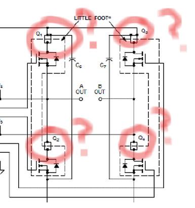
L1 and L2 are actual inductors, which are optional. A0 and B0 are the outputs of the H-bridge - connect these to one coil of a stepper motor. from the appnote:

"Finally, space has been provided for filter reactors, L1 and
L2, and filter capacitors, C1 and C2, to provide filtering of
PWM switching components from appearing at output
terminals AO and BO."


--
קיבלת הודעה זו מכיוון שאתה מנוי לקבוצה 'TAMI' בקבוצות Google.
כדי לבטל את המנוי לקבוצה הזו ולהפסיק לקבל ממנה הודעות דוא"ל, שלח הודעת דוא"ל אל hasadna+u...@googlegroups.com.
כדי לפרסם הודעות בקבוצה זו, שלח דוא"ל ל-has...@googlegroups.com.
לאפשרויות נוספות בקר ב-https://groups.google.com/groups/opt_out.


jr

unread,
Mar 17, 2013, 4:53:21 AM3/17/13
to has...@googlegroups.com
thanks Guy.
The LC filters I can safely omit if i am not doing PWM?

jr

unread,
Jun 1, 2013, 1:35:26 PM6/1/13
to has...@googlegroups.com
Over the last year we've successful killed about 4 polulu hbridges which can't take being connected w no load (apparently)
would a parallel resistance of e.g. 20x motor resistance fix this?
there is a voltage spike (i guess) when connected w no load , as transistor drive kamikaze's in an attempt to ram current through an infinitely small pipe
anyone who actually knows the failure mode pls chip in, a ckt that dies on no load is a lame ckt . maybe we can improve on polulu.

Yair Reshef

unread,
Jun 1, 2013, 1:39:20 PM6/1/13
to has...@googlegroups.com

Yair Reshef

unread,
Jun 2, 2013, 5:04:02 PM6/2/13
to has...@googlegroups.com
protection for usb from currents but might be adaptable
http://www.electronics-lab.com/blog/?p=21952


the ramps1.4 stepper shield uses the same driver 
and i dont see any additional protection

jr

unread,
Jun 14, 2015, 4:35:04 PM6/14/15
to has...@googlegroups.com
Looking for pinouts on a DB25 connector for a stepmotor driver.
The DB25 connects to an opto-isolator board that then connects to the actual driver 
which is an IB1010 .  

The board itself is apparently a creo-scitex board  - 
creo products inc stepper drive I/F 17-1303A-G   , PCB13094v0.

From looking at the IB1010 inputs it seems the thing wants step and direction signals.
And from the DB25 standards it seems DB25 pins 2-9 are the chief suspects to be carrying data.

So I connected the DC HV input to 24V (minimum for the board) 
connected DB25 # 25 to ground , and tried giving 5V to each of DB25 #2-#9 in turn,
with a 40k resistor from phase A + to phase A - and another from phase B+ to B- to 
fake the motor coils.
At some point not related to the 5v tests , I got 24V on both resistors, and it wouldnt turn off 
till i turned off the 24V psu.  
Another things is a red 'fault' light comes on when I hit DB pins # 6 or #13 ,
and pin DB#12 was connected to DB25 .  The other DB pins that i blv.  supposed to be ground (#18-24) were floating - 
maybe i need to ground those?
IMG_20150614_232728.jpg
IMG_20150614_232754.jpg
IMG_20150614_232807.jpg
IMG_20150614_232705.jpg

Guy Ovadia

unread,
Jun 14, 2015, 4:38:11 PM6/14/15
to has...@googlegroups.com
jr, I think you should desolder the IB1010 and use it stand-alone. There's little hope to decipher the Creo board without unreasonable amount of work.
I used these guy's little brothers (IB462 I think) for a past geekon project (the tank that shoots cherry tomatoes).

good luck :)


--
archive and web access >https://groups.google.com/forum/#!forum/hasadna
---
‏קיבלת את ההודעה הזו מפני שאתה רשום לקבוצה 'TAMI' של קבוצות Google.
כדי לבטל את הרישום לקבוצה הזו ולהפסיק לקבל ממנה דוא"ל, שלח אימייל אל hasadna+u...@googlegroups.com.
כדי לפרסם בקבוצה הזו, שלח אימייל אל has...@googlegroups.com.
לאפשרויות נוספות, בקר ב-https://groups.google.com/d/optout.

jr

unread,
Oct 22, 2016, 8:07:28 AM10/22/16
to TAMI
Is this stepper  shield good to go?  Tal and I are up to another workshop and wanted to do a stepmotor demo , may as well hit another bird.
I guess i put this .sch into a spice simulator to make sure all is good?
then send the sch to chyna? 

Yair Reshef

unread,
Oct 22, 2016, 8:15:41 AM10/22/16
to has...@googlegroups.com
we are sending a few boards real soon. 
ronen eduBoard[1] is coming a long
and another nano+rf24[2] shield im working on. 

so check its cool and we can go for it.


כדי לבטל את הרישום לקבוצה הזו ולהפסיק לקבל ממנה אימייל, שלח אימייל אל hasadna+unsubscribe@googlegroups.com.

כדי לפרסם בקבוצה הזו, שלח אימייל אל has...@googlegroups.com.
לאפשרויות נוספות, היכנס ל-https://groups.google.com/d/optout.


--
yair99@gmail / irc: shekel#OFTC / she...@0x2c.org+972-50-6301212

jr

unread,
Oct 22, 2016, 8:41:58 AM10/22/16
to TAMI
we're looking for a stepper driver that can handle dc also ,the A4988 in the shields/stepperDriver plan can't handle apparently.
alternate plan is resuscitate the 'diy driver' zvika/udi/me started way back.  
i put those diy plans in the github here (shields/diyStepperDriver) 
כדי לבטל את הרישום לקבוצה הזו ולהפסיק לקבל ממנה אימייל, שלח אימייל אל hasadna+u...@googlegroups.com.

כדי לפרסם בקבוצה הזו, שלח אימייל אל has...@googlegroups.com.
לאפשרויות נוספות, היכנס ל-https://groups.google.com/d/optout.

jr

unread,
Jun 21, 2019, 5:48:25 PM6/21/19
to TAMI
for implementing an hbridge, In the past I've connected an arduino to mosfets as in fig. h2.png , where one mostet is a lowside switch and the other pmos is controlled by another nmos allowing the arduino
to run it from 0-5V tho the power supply may be 20V for instance.  (only one side of the hbridge is shown , other side is connected similarly)

But i was wondering if I cant dispense with the extra nmos running the pmos by running the arudnio output as an input which has high impedance - when in that
state the pmost gate will go high  , and when run as output at 0V it can be brought low.
So far so good
But the arduino input can only handle up to 5V, if connected as such the 20V will hit the arduino and cause trouble.
I have the feeling there is some way to pull this off, can any one figure it out??
h1.png
h2.png

Paul Cohen

unread,
Jun 22, 2019, 10:26:29 AM6/22/19
to TAMI
1. It seems to be the simplest (and cheapest) method of level translation.
2. Think about protecting the arduino in case of short/open in the power mosfets.

Paul Cohen

unread,
Jun 22, 2019, 10:38:44 AM6/22/19
to TAMI
BTW, Why you use an IRF530 to drive the Power MOSFETS?

Guy Ovadia

unread,
Jun 22, 2019, 11:18:45 AM6/22/19
to TAMI
One other consideration here - are you PWM'ing this at a high speed (kHz and above)? is so, a resistor is a poor choice for gate driving, because it turns on the transistor slowly. This is bad since a transistor only dissipates a small amount of power when it's fully open or fully closed, but a lot of power in the middle range (multiple orders of magnitude more, for many circuits). That's why you want to keep the time it gets turned on to be a very small fraction of the PWM cycle.

--
archive and web access >https://groups.google.com/forum/#!forum/hasadna
---
‏קיבלת את ההודעה הזו מפני שאתה רשום לקבוצה 'TAMI' של קבוצות Google.
כדי לבטל את הרישום לקבוצה הזו ולהפסיק לקבל ממנה אימייל, שלח אימייל אל hasadna+u...@googlegroups.com.
כדי לפרסם בקבוצה הזו, שלח אימייל אל has...@googlegroups.com.
כדי להציג את הדיון הזה באתר, היכנס ל-https://groups.google.com/d/msgid/hasadna/383b5cb8-0a8d-44e8-902f-f811e23d23df%40googlegroups.com.

jr

unread,
Jun 22, 2019, 2:19:29 PM6/22/19
to TAMI


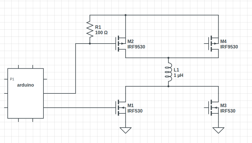
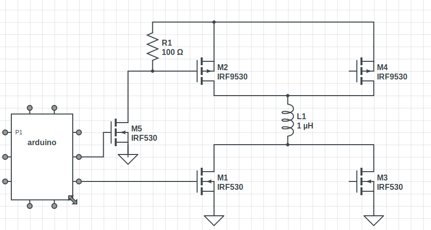
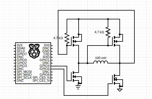
I think I have solved it, albeit without 3-state, fig below


I connect the gates of the pmos to the sources of the 'cooperating' nmos (the one that's 'on' when a given pmos is on)

Guy iiuc I should use as small as possible a resistance for the pullups , to prevent the phenom you speak of namely gate capacitance with pullup resistance

leading to a turn-on time constant that's an appreciable fraction of the pwm period

h3.png


On Saturday, June 22, 2019 at 6:18:45 PM UTC+3, Guy Ovadia wrote:
One other consideration here - are you PWM'ing this at a high speed (kHz and above)? is so, a resistor is a poor choice for gate driving, because it turns on the transistor slowly. This is bad since a transistor only dissipates a small amount of power when it's fully open or fully closed, but a lot of power in the middle range (multiple orders of magnitude more, for many circuits). That's why you want to keep the time it gets turned on to be a very small fraction of the PWM cycle.

On Sat, 22 Jun 2019 at 17:38, Paul Cohen <paul...@gmail.com> wrote:
BTW, Why you use an IRF530 to drive the Power MOSFETS?

On Monday, October 8, 2012 at 2:31:35 AM UTC+2, Guy Ovadia wrote:
Hi,

I'm looking for a DC motor (H-bridge) driver board with the following specs:

- over 3A current (preferably 5A or more so it's not used at max capacity)
- over 24V voltage (again, 28V or more is better)
- looking for a ready to use board, as opposed to a bare chip
- fast availability is a plus (someone selling in Israel, or a fast shipment from abroad).
- I don't want undocumented "who knows what's that chip"-based boards, like the multiple offerings I found on eBay. I want good documentation.

recommendations?

thanks!
Guy.

--
archive and web access >https://groups.google.com/forum/#!forum/hasadna
---
‏קיבלת את ההודעה הזו מפני שאתה רשום לקבוצה 'TAMI' של קבוצות Google.
כדי לבטל את הרישום לקבוצה הזו ולהפסיק לקבל ממנה אימייל, שלח אימייל אל has...@googlegroups.com.

Paul Cohen

unread,
Jun 23, 2019, 8:33:48 AM6/23/19
to TAMI
Very elegant and nice solution!

Guy Ovadia

unread,
Jun 23, 2019, 5:49:25 PM6/23/19
to TAMI

Guy iiuc I should use as small as possible a resistance for the pullups , to prevent the phenom you speak of namely gate capacitance with pullup resistance

leading to a turn-on time constant that's an appreciable fraction of the pwm period

Yes. Although, it may be difficult to do so with a resistor. In fact, to achieve decent efficiency the normal approach is to use a dedicated gate-driver chip that turns the gates on and off with brief, strong currents (100's of mA to even several A's, for a very short time). For the same reason, pushing the gates with a GPIO is quite marginal. However, if the load isn't too high current and you don't mind losing a few watts in the transistors - or if you PWM it slowly or not at all - it may be acceptable.

regarding the arrangement you showed in the last email, you're playing a very dangerous game here. I think you might get shoot-through (opening of both the top and bottom transistors on the same side, shorting the supply leading to the release of their magic smoke). Think about it like this: let's say you set GPIO4 to High. This will certainly turn the bottom-left and the top-right transistors, which is desirable. However, it seems like there's a race to also open the top-left transistor since the voltage on that transistor's gate (pulled up by the 4.7k resistor) now has a path to ground, through the load and the bottom-left transistor. What will happen first? that problematic scenario or the opening of the top-right transistor (now strongly pulling the right side of the load to VDD and preventing the shoot-through)? I don't know. depends on the capacitance of all the nodes here, I suspect. I suppose you could start applying deliberate capacitors here and there in an effort to ensure the winning of the "correct" side in this race condition, but I don't recommend it - it's not a robust solution and may suddenly burst into flame if the conditions suddenly change from what you expect (load behavior changes etc).

 
כדי לבטל את הרישום לקבוצה הזו ולהפסיק לקבל ממנה אימייל, שלח אימייל אל hasadna+u...@googlegroups.com.

כדי לפרסם בקבוצה הזו, שלח אימייל אל has...@googlegroups.com.
כדי להציג את הדיון הזה באתר, היכנס ל-https://groups.google.com/d/msgid/hasadna/d19aee15-9bff-4a85-981a-4f926a149755%40googlegroups.com.

Paul Cohen

unread,
Jun 24, 2019, 4:22:31 AM6/24/19
to has...@googlegroups.com
מסתבר ש-"אין ארוחות חינם" נכון גם כאן.

בתאריך יום ב׳, 24 ביוני 2019, 0:49, מאת Guy Ovadia ‏<guyov...@gmail.com>:
‏קיבלת את ההודעה הזו מפני שאתה רשום לנושא בקבוצה 'TAMI' של קבוצות Google.
כדי לבטל את הרישום לנושא הזה, היכנס ל-https://groups.google.com/d/topic/hasadna/v5AukjqiyV0/unsubscribe.
כדי לבטל את הרישום לקבוצה הזו ולכל הנושאים שלה, שלח אימייל אל hasadna+u...@googlegroups.com.

כדי לפרסם בקבוצה הזו, שלח אימייל אל has...@googlegroups.com.
h3.png
Reply all
Reply to author
Forward
0 new messages