PAL-2 board design question
138 views
Skip to first unread message

GN Liu
Dec 4, 2022, 2:28:34 AM12/4/22
to PAL 6502 computer
Hello community,
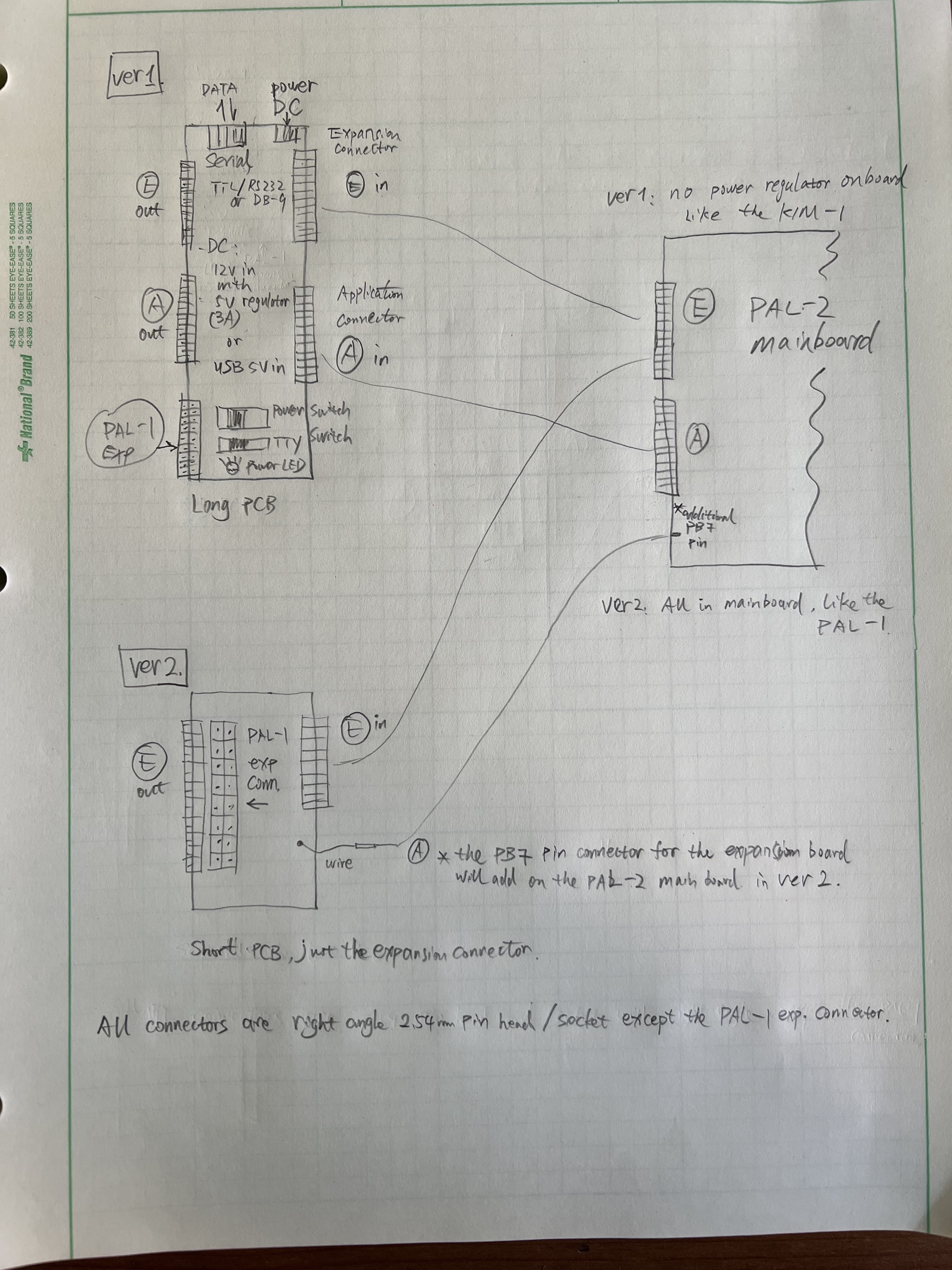
I'm thinking about the board design of PAL-2. I draw a sketch about the two designs of the PAL-2 system, one like the KIM-1 and one like the PAL-1. Which one do you like or show us your idea.
and sorry about my poor handwriting...
Thanks!
Liu

Hans Van Slooten
Dec 4, 2022, 2:38:16 AM12/4/22
to GN Liu, PAL 6502 computer
I tend to lean towards historical accuracy, so the more you make it like the original KIM-1 the better, in my opinion.
Also, your handwriting is much better than mine.
Hans V.
--
You received this message because you are subscribed to the Google Groups "PAL 6502 computer" group.
To unsubscribe from this group and stop receiving emails from it, send an email to pal6502+u...@googlegroups.com.
To view this discussion on the web visit https://groups.google.com/d/msgid/pal6502/cb8d507c-8d02-4d01-bbd7-983602dc058cn%40googlegroups.com.
For more options, visit https://groups.google.com/d/optout.

Hans Otten
Dec 4, 2022, 9:40:13 AM12/4/22
to PAL 6502 computer
I like also more resemblance to the KIM-1. Board with the layout of the original. It will not be a one on one replica, edge PCB connectors are bulky, and expensive, so PIN connectors are fine.
A daughter board attached to the Application connector for power and RS232 is in the KIM-1 style. Male -Female, so no cable required.
The PAL-1 expansion connector will require a small board attached to the Expansion connector and some wires to the Application connector like PB7. and TAPE.

Will Senn
Dec 4, 2022, 10:41:08 AM12/4/22
to pal...@googlegroups.com
I like the KIM-1 look and agree with
the Hans's :). If I'm reading it correctly, it looks like it
wouldn't expand the bulk of the PAL-2, otherwise I might have to
reconsider. As it is, I'd say lean toward the historical
aesthetics.
Will
Will
To view this discussion on the web visit https://groups.google.com/d/msgid/pal6502/ca499558-382d-4fea-974e-dab313b17acen%40googlegroups.com.

Jeremy Starcher
Dec 4, 2022, 11:36:09 AM12/4/22
to PAL 6502 computer
I like the idea of seeing the edge connectors as well, the retro aesthetics.
Think it would be fun to see a PAL-1 running with some original KIM-1 accessories.

Jim McClanahan
Dec 4, 2022, 3:13:34 PM12/4/22
to PAL 6502 computer
I like the Ver 1 long PCB.
I do worry a bit that stray capacitance might start flaring up with some strange symptoms at some point. The data sheet for the original NMOS 6502 rates the address and data lines at "one standard TTL load and 130 pf". I actually dug out my capacitance meter and tried to figure out something that would give a meaningful indication of capacitance. I measure 36 pF between ground and A0 on just the expansion bus board (with no cards installed) and the ribbon cable attached (but not going to the PAL-1 motherboard). The rule of thumb I learned in college was to assume about 10 pF for each CMOS input. So with 2 ROMs, 2 RIOTs, 2 RAMs, address decoding, and all of the traces on the mother board (and on any expansion boards) it feels like you would be starting to get close. (10 pF is, I believe, conservatively high. And I'm assuming (which I think is accurate) that you'd see significant input capacitance even if the chip wasn't selected.) I don't know if anyone else sees it, but my expansion bus is already a bit finicky when it comes to where the boards are plugged in.
If I was more ambitious (actually I'm afraid I'll break something) I'd pull all the chips and measure the capacitance from the motherboard's processor socket through the system including the expansion bus. That would give you a reasonably accurate measure of non-IC capacitance.
Thanks,
Jim W4JBM
Jim McClanahan
Dec 4, 2022, 8:24:41 PM12/4/22
to PAL 6502 computer
I'll correct myself here. The RIOTs are definitely not CMOS. :-)
--
You received this message because you are subscribed to a topic in the Google Groups "PAL 6502 computer" group.
To unsubscribe from this topic, visit https://groups.google.com/d/topic/pal6502/xeGiyD08CnM/unsubscribe.
To unsubscribe from this group and all its topics, send an email to pal6502+u...@googlegroups.com.
To view this discussion on the web visit https://groups.google.com/d/msgid/pal6502/99672320-ddf5-4167-8b24-bbe45db779ccn%40googlegroups.com.
Hans Otten
Dec 5, 2022, 5:52:52 AM12/5/22
to PAL 6502 computer
Jim has a point, the NMOS 6502 may have problems driving all those ICs connected to the data and address bus. In the old days, we used buffer IC's, especially for memory. since that meant many many IC's.
With the current low power large capacity ICs it is not so critical, we are still at 1 MHz. But long wires like the cable between teh PAL-1 and the motherboard, which itself adds to the path length. We get close to the maximum.
With the current low power large capacity ICs it is not so critical, we are still at 1 MHz. But long wires like the cable between teh PAL-1 and the motherboard, which itself adds to the path length. We get close to the maximum.
That is why I propose for the PAL-2 not to have a cable between PAL-2 and extension board, but a direct connection via the pin connectors.
Hans Otten
Dec 5, 2022, 6:01:41 AM12/5/22
to PAL 6502 computer
With the WD65C02, as Liu is planning ti use, the problem will be different. Driving capability is higher, rise and fall of signals is steeper, since it is a faster device. Long cabling capacitance will cause the rise and fall to be slower, which the CPU may not like. So still reason enough to limit the path length of signals.
Jim McClanahan
Dec 5, 2022, 8:58:13 AM12/5/22
to PAL 6502 computer
With CMOS, ground bounce may become an issue. I've struggled with that on a 6800 board I've built. A lot of time you can't just take the old design and drop in higher speed CMOS chips. I get bounce on both transitions. The bounce is fast enough that older, slower chips don't even have time to respond, but it does cause occasional flakey behavior, so I've been working to tame it for a while now.
Thanks,
Jim W4JBM

Dimitri
Dec 5, 2022, 11:04:35 AM12/5/22
to PAL 6502 computer
I prefer ver1 - having access to K0-K7 (B-J) on the Application connector will hugely simplify expansion boards.
Could you also please consider including a Molex / 4 pin peripheral power connector on the 'long PCB' to allow a regulated PC power supply to be directly connected. This should alleviate any power issues when multiple/many expansion cards are connected - I currently fear for my wall wart and the LM7805 on my PAL-1!
Many thanks,
:D
GN Liu
Dec 6, 2022, 8:54:41 AM12/6/22
to PAL 6502 computer
Thanks all!
My VPN almost fully block these days, so I can't reply in time, but I'll read each of your typing when I get a chance "online".
Thanks,
Liu
Liu
GN Liu
Dec 6, 2022, 8:57:50 AM12/6/22
to PAL 6502 computer
Hans V,
I find a new model LED display just looks like the original KIM-1, narrow and tiny, and I'll use it on the PAL-2.
The PAL-2 will not very historical accuracy, but will be more accuracy than PAL-1.
Thank you for complimenting my writings...
Liu
GN Liu
Dec 6, 2022, 9:00:56 AM12/6/22
to PAL 6502 computer
Hans,
of course no cables, they're pin connectors, male-female type.
Do you prefer two small daughter board or one long daughter board? the long daughter board actually not that long as the KIM-1 because the PIN connector is shorter than the edge connector.
Thanks,
Liu
GN Liu
Dec 6, 2022, 9:06:25 AM12/6/22
to PAL 6502 computer
Will,
The PAL-2 will use bigger key switches, I'll post it to the group later, they're similar to the cherry ML switches. so it won't look like the KIM-1, but I think I can layout the components like the KIM-1.
Thanks,
Liu
GN Liu
Dec 6, 2022, 9:09:04 AM12/6/22
to PAL 6502 computer
Jeremy,
The idea is very interesting, PAL-1/2 running with some expansion board for KIM-1~ Maybe another daughter/converter board for the classical edge connectors?
Thanks,
Liu
GN Liu
Dec 6, 2022, 9:16:59 AM12/6/22
to PAL 6502 computer
Jim,
I also prefer the Ver.1.
Your thoughts are always deep! But I don't know how to avoid it if there is a problem... I'll make few board for testing, and see if they're stable.
I also want to design the PCB like the old time style, just traces, no copper plates in free area, any help?
Thanks,
Liu
GN Liu
Dec 6, 2022, 9:25:11 AM12/6/22
to PAL 6502 computer
Tastypies,
I remember your suggestion before, the Molex 4, I'm looking for an elegant way to mount it on the board.
Thanks,
Liu
Jim McClanahan
Dec 6, 2022, 9:54:54 AM12/6/22
to PAL 6502 computer
There are adapters that let you take a pin connector and convert it to an edge connector. I used these before I remade a drive cable for putting 3.5" drives in my Cromemco (to look like 8" drives). I suspect there aren't many original KIM-1 peripherals or cards to plug into an old style edge connector.

Ronny Ribeiro
Dec 6, 2022, 10:05:42 AM12/6/22
to GN Liu, PAL 6502 computer
Liu,
the vias in the PAL-1 board could have been thicker. I think you could optimize them for PAL-2. Ground and power planes are good for shielding and also for stabilizing voltages through its added capacitance. I think the display profile should match the keypad size, aesthetically. The keypad is gonna be pronounced, so the display should match, I'm my opinion.
Regards,
Ronny
--
You received this message because you are subscribed to the Google Groups "PAL 6502 computer" group.
To unsubscribe from this group and stop receiving emails from it, send an email to pal6502+u...@googlegroups.com.
To view this discussion on the web visit https://groups.google.com/d/msgid/pal6502/b7874b68-b3c3-45d5-b139-ccbcc21bfe2fn%40googlegroups.com.
Jim McClanahan
Dec 6, 2022, 10:40:51 AM12/6/22
to PAL 6502 computer
I'm not a PCB design person, but using traces for ground runs instead of having a ground plane will probably have mixed results. The advantage is probably a lower overall capacitance between ground and the address and data lines. But ground traces can start to look like inductors at the higher speed switching signals modern CMOS will have. That may make it difficult to decouple the power supply for some of the chips. (You typically decouple from the supply to ground, but in this situation "ground" may not be the same for the overall circuit and the individual chip feed with a trace for ground.) I've seen this with high-speed memory chips--no matter how hard I tried to decouple it, there was noise.
It's just a gut feel, but I think that going to CMOS and removing copper from the board are both going to tend to push things closer to the edge. At the end of the day, I think the CMOS devices you are trying to drive are going to be the big contributors to the problem. (A bigger problem than any issues with the capacitance caused by the ground plane.) On the 6800 board I've been tinkering with, the 1.84 MHz oscillator has bounces (oscillation) on both transitions that is well over 10x the frequency of the crystal. In that situation, having the extra copper as a ground plane helps because it reduces the impedance from the ground pin of any IC to actual circuit ground.
The worst case always is where sometimes things work and sometimes they don't. One batch of chips might have characteristics different enough from another to make a swing in behavior. If you get a prototype built, I'd take a close look at the clock, address, and data lines with an oscilloscope to see if there is bounce/ringing. Sometimes the ringing is at such a high frequency that things seem to work because devices can't switch as fast as the ringing. If you find that, you know you have problems.
Probably Plan B would be to stick with the NMOS processor instead of going with the later CMOS ones. (Although it would be nice to have the added instruction the later versions bring.)
Thanks,
Jim W4JBM
GN Liu
Dec 6, 2022, 8:47:10 PM12/6/22
to PAL 6502 computer
Hi Ronny,
Got your opinion!
aesthetic
Liu
GN Liu
Dec 6, 2022, 8:47:55 PM12/6/22
to PAL 6502 computer
Thanks Jim!!!
Reply all
Reply to author
Forward
0 new messages