X-axis Wiring Harness Extension/Upgrade
1,429 views
Skip to first unread message

Jake
Jul 6, 2013, 11:26:16 AM7/6/13
to make...@googlegroups.com
Hi everyone. I finally got the parts to put together an X-axis wiring harness upgrade. This upgrade uses Cicoil Hi-Flex cable. (http://media.digikey.com/PDF/Data%20Sheets/CICOIL%20PDFs/Hi_Flex_Unshielded_Cables.pdf) This cable is rated for "continuous motion", unlike the PVC jacketed IDC cable used by MBI. The data sheet doesn't mention this, but I contacted the manufacturer who told me that it is good for sharp bends in static applications as well.
It is a really nice, high quality ribbon cable. The conductors are insulated by a water-clear silicone jacket. I chose 24AWG wire, which is a little thicker than than the 28AWG wire used by MBI. This should be better at elevated chamber temperatures of the Rep 2X.
It does, however, take a little skill to work with. The conductors are not "zipable" like IDC ribbon, which means you can't just tear the conductors apart. This means some precise cutting with an exacto knife. I decided to liberally use heat shrink tubing to make sure that there were no exposed conductors along my slices-- and that thinner insulation left were a cut was made was supplemented by a little heat shrink.

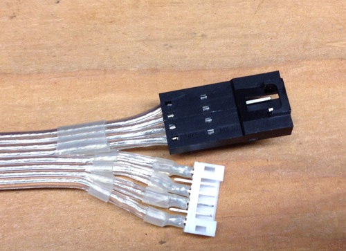
I modified my "Replicator 2/2X X-Harness Strain Relief" thing (http://www.thingiverse.com/thing:99811) to work with the new cable. Also you need a little clip to replace the zip tie that holds the harness.


I would say it takes a medium level of skill do to this upgrade. You need cut through the insulation pretty precisely. You need to solder and crimp tiny pins on the end of the cable. If you're like me, you need to apply a liberal amount of heat shrink tubing. You need to print a few parts (before you start) too.
You need about 16" of the cable to make an extension for the active motion area of the cable. I had to buy 50ft minimum order. If people are interested, I'll sell lengths off the spool to subsidize the purchase. I'm not looking for a profit, but just to cover the cost of the cable, connectors, pins, and shipping (and any materials left on my shelf, ideally) I also bought some extra connectors and pins so I can put together a "kit" of sorts.

If you're interested, let me know, and depending on interest I'll come up with a fair price... but I imagine a kit would be around $20, possibly less, depending on interest. If interest is more than I can supply based on my "inventory" it'll be first come, first serve until stock is depleted... Watch on this thread for info when I'm ready to start accepting orders.
Also if anyone has any suggestions for improvement, I'd also value your opinions.

Bottleworks
Jul 6, 2013, 12:50:11 PM7/6/13
to make...@googlegroups.com
Looks great! I'm ready to order.

Infinityplusplus
Jul 6, 2013, 12:58:05 PM7/6/13
to make...@googlegroups.com
I will order one when your ready. Looks great.

Adam Nerva
Jul 6, 2013, 1:13:38 PM7/6/13
to make...@googlegroups.com
Count me in too!

Divine Shadow
Jul 6, 2013, 1:33:07 PM7/6/13
to make...@googlegroups.com
It could be only a matter of time before the current stock cable flexes for the last time, I think this would be a wise choice, count me in!

Jonathan Wild
Jul 7, 2013, 2:45:53 AM7/7/13
to make...@googlegroups.com
Put me down for one :)

Bryon Miller
Jul 7, 2013, 10:17:28 AM7/7/13
to make...@googlegroups.com
If this comes with easy to follow instructions, I'll buy one! I was going to just buy a bunch of cables from MBI to just have on hand so I'd be prepared when it fails, but I'd really prefer this. I'd pay more for one that has the slices and everything already done.
On Saturday, July 6, 2013 8:26:16 AM UTC-7, Jake wrote:
On Saturday, July 6, 2013 8:26:16 AM UTC-7, Jake wrote:
Message has been deleted

Cal Bachand
Jul 7, 2013, 9:50:39 PM7/7/13
to make...@googlegroups.com
I'm in for sure!

DonFrambach
Jul 8, 2013, 1:05:59 AM7/8/13
to make...@googlegroups.com
Looks very interesting. I will order too when you're ready.
On Saturday, July 6, 2013 8:26:16 AM UTC-7, Jake wrote:
On Saturday, July 6, 2013 8:26:16 AM UTC-7, Jake wrote:
Jake
Jul 8, 2013, 9:04:44 AM7/8/13
to make...@googlegroups.com
Some more detail for folks:
So some more notes for people.
My intention is to sell off the remaining connectors and parts, and I'm happy to provide documentation about what I did, but I'm not claiming this is a "fix" or will 100% solve the problem with the X-cable harness. I think its a fix, but I can't guarantee that it won't fail in spectacular fashion at some later date. Nor am I claiming that my installation is either correct or ideal. Its just what I happened to come up with. I'd invite people to take the cable and connectors and come up with their own solution, and maybe one better than my own. I'll do some math today and come up with the "fair price".
As I mentioned, the upgrade is not trivial. You could just splice in this cable directly into the exiting harness, which might be easier, but involves cutting the existing harness. Crimping the pins is difficult, even with the right crimp tool, and I'm guessing no one has the right crimp tool. Also, the insulation is pretty thick on this cable, and you can't actually crimp the pins such that the "strain relief" portion of the crimp bites into the insulation. My process was as follows:
- Tin the wire with a THIN coat of solder
- Tin the inside of the crimp connector (only the crimp area, not near the active pin area) with a THIN coat of solder
- Tack the wire to the connector with the iron
- Crimp the pin. I had a crimp tool that wasn't the right one, but did somewhat of a passible job. You could do this carefully with needle nose pliers and a steady hand
- Heat the completed assembly with a touch of solder to reflow the solder and get a nice finished solder job to the now-crimped pin. Important not to leave a glob of solder, you can't change the outer diameter of the pin crimp area otherwise it won't press into the housing.
- Use a punch tool to carefully push the pins into the housing.
Its important to make sure you're building an "extension cable" not a "crossover cable", so you have to pay particular attention to the orientations of the connectors otherwise you could be having a bad day, doing damage to your mightyboard, endstop, motors, etc.


Again, the cable is not "zipable" so you can't just tear perfect slices between the conductors. This takes a patient and steady hand. I did mine under the magnifying glass, and still wasn't confident in the insulation after my slicing job. Hence I used a lot of heat shink to make sure that there were no potential areas where a short could occur. Here's a diagram trying to explain the difficulty and concern with slicing this cable. The entire cable is .5" across, so this is close-quarters cutting.

Basically, this isn't rocket science, but you have to know what your doing, have a steady hand, be good with a fine-tipped soldering iron, and double check your work. I checked the entire cable for shorts and made sure the wiring was correct for a straight-through extension with my meter once I was done, before putting it in the machine.
As always, standard disclaimers apply. I'm just selling off extra individual components for use as you see fit. I take no responsibility for how to use the parts. The parts and information are provided "as is" and any express or implied warranties, including, but not limited to, the implied warranties of merchantability and fitness for a particular purpose are disclaimed. In no event shall the author be liable for any direct, indirect, incidental, special, exemplary, or consequential damages (including, but not limited to, procurement of substitute goods or services; loss of use, data, or profits; or business interruption) however caused and on any theory of liability, whether in contract, strict liability, or tort (including negligence or otherwise) arising in any way out of the use of this software, even if advised of the possibility of such damage.
Jake
Jul 8, 2013, 9:41:02 AM7/8/13
to make...@googlegroups.com
Also a nice video here of working with this kind of cable. http://www.youtube.com/watch?v=XBSupfMHNiw
Jake
Jul 8, 2013, 4:41:28 PM7/8/13
to make...@googlegroups.com
After looking at the pricing, I'm thinking $15.00 + $5.00 for flat rate small box shipping for the following:
- 18" of Cicoil High Flex 8 Conductor 24 AWG cable. (My cable is 16" so a little extra.)
- One motor connector set (1 male 6-pin header, one female 6 pin housing, and 4 crimp pins)
- One endstop connector set (1 female housing, 1 male housing, 4 male crimp pins, 4 female crimp pins)
Not making a real profit here, in fact, will probably take a bit of a loss-- That's fine my me, I'm not complaining; I wanted the upgrade for myself. I just want to be transparent about the pricing. If I can, I'd like to offset some of the cost, though, so I did a little rounding up and dividing out some of the other costs (like shipping/tax). Also based on the current count, I'm thinking that there isn't a huge interest and the number of these kits (less than 20) that will actually sell, so I've accounted for about 15 sales to help offset what's going to go unused.
Also there is apparently a shortage of small flat-rate boxes in my area. The post office told me I had to order them. So I did, but it might take a week to get here. While I can use envelopes, I don't think that we want to crease the fancy and expensive cable to fold it over into a shipping envelope. So when I get the shipping supplies I'll start taking orders.
Bradley Pearce
Jul 8, 2013, 5:01:13 PM7/8/13
to make...@googlegroups.com
USPS will take longer then they state for boxes to arrive. I waited
close to a month for an order of boxes.
> --
> You received this message because you are subscribed to a topic in the
> Google Groups "MakerBot Operators" group.
> To unsubscribe from this topic, visit
> https://groups.google.com/d/topic/makerbot/iqvHir0F67k/unsubscribe.
> To unsubscribe from this group and all its topics, send an email to
> makerbot+u...@googlegroups.com.
> For more options, visit https://groups.google.com/groups/opt_out.
>
>
>
--
Bradley Pearce
BC Technological Solutions, LLC
http://www.BCTechnologicalSolutions.com
close to a month for an order of boxes.
> You received this message because you are subscribed to a topic in the
> Google Groups "MakerBot Operators" group.
> To unsubscribe from this topic, visit
> https://groups.google.com/d/topic/makerbot/iqvHir0F67k/unsubscribe.
> To unsubscribe from this group and all its topics, send an email to
> makerbot+u...@googlegroups.com.
> For more options, visit https://groups.google.com/groups/opt_out.
>
>
>
--
Bradley Pearce
BC Technological Solutions, LLC
http://www.BCTechnologicalSolutions.com
Divine Shadow
Jul 8, 2013, 5:38:03 PM7/8/13
to make...@googlegroups.com
Thanks for the info, I am in all the way, just say when. If you can reserve one that would be great.
-Jim

isaac
Jul 9, 2013, 12:04:41 PM7/9/13
to make...@googlegroups.com
Please count me in too!
On Saturday, July 6, 2013 8:26:16 AM UTC-7, Jake wrote:
On Saturday, July 6, 2013 8:26:16 AM UTC-7, Jake wrote:

Jake Dambergs
Jul 9, 2013, 5:52:58 PM7/9/13
to make...@googlegroups.com
+1 Looks great!
Jake D

_kyle
Jul 9, 2013, 9:31:13 PM7/9/13
to make...@googlegroups.com
I'm in too. My X-Axis cable is totally hosed as of this weekend. I'll be curious to see of MB can replace it before you can :).
Incidentally, my issue happened after a couple of really large prints that repeatedly took me right up to the limit of the Y-Axis.
Thanks for putting this together.

David Celento
Jul 11, 2013, 8:35:25 AM7/11/13
to make...@googlegroups.com
I'm in. Nice work!
~Dave

Qtrain23
Jul 11, 2013, 3:51:59 PM7/11/13
to make...@googlegroups.com
I'd be interested in one

Bonekollector
Jul 11, 2013, 5:00:52 PM7/11/13
to make...@googlegroups.com
Id be interested in one :-)

SMT Guy Austin, Texas
Jul 12, 2013, 8:24:12 AM7/12/13
to make...@googlegroups.com
w
Jake
Jul 14, 2013, 8:24:03 AM7/14/13
to make...@googlegroups.com
Hi everyone.
Please review the full page of information here: http://www.extrud3d.com/x-harness
Bottleworks reminded me that I didn't account for paypal fees, so the final price will be $16 + $5 shipping (usps flat rate small box, which is more than $5 but I'm rounding)
Since this is a small-run kind of thing, I'm not going to setup a store front or anything. Just email me (you can use a private message to the email address I use to post to the google group, or if you prefer, there is an address listed at the end of the page (http://www.extrud3d.com/x-harness). I'll send you a paypal request for $21, and ship it out as soon as practical once I receive payment.
Your payment buys you:
- 18" of Cicoil High Flex 8 Conductor 24 AWG cable. (It took 16" to make the cable, so 18" leaves a little extra.)
- One motor connector set (1 male 6-pin header, one female 6 pin housing, and 4 crimp pins)
- One endstop connector set (1 female housing, 1 male housing, 4 male crimp pins, 4 female crimp pins)
What's NOT included: heat shrink tubing, solder, any tools, the 3d printed parts.
Again, I'm just providing raw materials to you, and make no warranties that you'll be able to successfully and safely execute such as upgrade. See all the disclaimers on http://www.extrud3d.com/x-harness before ordering.
And of course, any questions, post here.
Thanks for the interest, and helping me make a use of the 48 feet of remaining cable.
_kyle
Jul 14, 2013, 3:48:42 PM7/14/13
to make...@googlegroups.com
Thanks. One question after looking over your instructions. It looks like you've preserved the original XYZ and endstop harnesses and this cable is strictly an extension. Is that right? Did you just tuck the excess cable from the harness under the bot?
And somewhat related: I'm just looking at the harness for the first time today, since mine is hosed and I'm expecting a replacement from MBI. Is there a reason they chose to use a single connector for the board and opt for a harness rather than having separate connectors for each motor and endstop? It'd sure be easier to service (or upgrade) if you only had to replace one cable.
Jake
Jul 15, 2013, 7:42:07 AM7/15/13
to make...@googlegroups.com
Yeah, my approach was to just make an extension. I folded up the original harness in the front vertical pillar using the original wire clips that were there. It is probably easier to cut and solder and splice directly into the cables rather than doing all the connector crimping, etc, but this way the original harness is left intact.
I can't speak to why MBI designed things the way they did. I haven't need any problems with it being in one cable. In fact, the original two cable design has the motor and endstop cables closer together (one on top of another). If you're worried about noise or something, I don't think its a concern but I'm not an expert. I've done a dozen or so prints on the new cable with no issue so far. Given that the motor and endstop signals are on separate headers on the mightyboard, the dual wire strategy might have been for that reason alone.

Big-E
Jul 15, 2013, 9:11:16 AM7/15/13
to make...@googlegroups.com
Payment sent, Thanks Jake!
Be sure to post in here when the part files are up on Thingiverse.
-Big-E
Be sure to post in here when the part files are up on Thingiverse.
-Big-E
Jonathan Wild
Jul 15, 2013, 8:18:41 PM7/15/13
to make...@googlegroups.com
Payment sent.
Thanks :)
Jake
Jul 15, 2013, 8:27:54 PM7/15/13
to make...@googlegroups.com
I posted the STL for the 3D printed parts on http://www.extrud3d.com/x-harness in the "Printed Parts" section. Keeping it off Thingiverse for now so that I don't get a flood of orders-- let's keep it between friends here in the group for now.
Also you'll need a small metric nut driver to install the clip part. I used one of the bits from this set: http://dx.com/p/precision-screw-drivers-toolkit-for-electronics-diy-45-piece-set-36203 It needs to be small enough to get in the countersink of the clip part.

Andy Soukup
Jul 16, 2013, 11:08:56 AM7/16/13
to make...@googlegroups.com
in the video they mentioned the use of RTV to seal things up. it may be better to try RTV instead of shrink wrap.
i'm not sure what crimper you use, but i use one similar to this. i use it for 0.1" header crimps and i've gotten good results. the trick is to use some pliers after crimping to narrow the crimp so that it fits into the header. it may not be the exact crimper for this exact terminal, but it works. For $35 you can't complain too much.
Jake
Jul 16, 2013, 11:14:01 AM7/16/13
to make...@googlegroups.com
Yeah, I did know about the RTV recommendation, but I didn't have any on hand when I did mine. I went with what I had.
I have a similar crimp tool but non-ratcheting, and it does work for the pins with care. I still like to tack the wire into the pin with solder so that it is stable while crimping, otherwise it can be a little tricky getting everything to line up in the crimper all at the same time.
Andy Soukup
Jul 16, 2013, 11:19:43 AM7/16/13
to make...@googlegroups.com
with the crimp tool, the crimp terminal will "stick" in the toolhead, so you only need two hands to make it happen. with the crimp terminals/headers i'm using, they fit pretty tight, so i'd imagine the addition of any solder may reduce the clearance and make them hard to assemble.
also, when crimping the terminals, pay attention to the rotation in respect to the harness. it'll be pretty hard to insert the terminals into the header if they're all pointing different directions.
thanks for the upgrade and all the details!
Jake
Jul 16, 2013, 11:25:41 AM7/16/13
to make...@googlegroups.com
Good points.
Also, I haven't tried this myself, but another idea for folks attempting this upgrade.
Based on the Endstop 1.2 schematic Thingiverse, on The middle 2 of the 4 endstop pins are GND. You probably only need one ground to the endstop. So you could possibly sacrifice the 4th conductor of 8 in the cable, use the exacto knife and cut right down the middle of the conductor and remove it completely. This would keep the insulation intact for the 3rd and 5th conductors of the cable, and separate the endstop wiring from the motor wiring by a disused conductor. Not sure if that makes any sense or if it would work any better.
Big-E
Jul 17, 2013, 5:49:52 PM7/17/13
to make...@googlegroups.com
Just got my flex cable parts in the mail. Everything looks good; The cable looks like it will hold up to the flexing just fine. Thanks again Jake!
I'll probably start putting it together tomorrow; I intend to take my time on this one. I'll be sure to post up the results when done.
-Big-E
I'll probably start putting it together tomorrow; I intend to take my time on this one. I'll be sure to post up the results when done.
-Big-E

RoboSysop
Jul 17, 2013, 6:03:22 PM7/17/13
to make...@googlegroups.com
My Makerspace would love to buy as much cable as you have.

Joseph Chiu
Jul 17, 2013, 6:05:52 PM7/17/13
to make...@googlegroups.com
I just received the cable kit parts from Jake as well.
I have some ideas on how to make it easier to make a working cable upgrade. Anyone in the Los Angeles area interested in being a guinea pig?
Wow. I can see now why Cicoil can charge so much for this cable. It's definitely not your common 0.1" ribbon cable. It's beefy but very flexible. If I didn't know better, I could easily have mistaken it for some kind of wire-reinforced timing belt or some such. As Jake pointed out in an earlier post, this not an easily "zipable" cable.
I have some ideas on how to make it easier to make a working cable upgrade. Anyone in the Los Angeles area interested in being a guinea pig?
--
You received this message because you are subscribed to the Google Groups "MakerBot Operators" group.
To unsubscribe from this group and stop receiving emails from it, send an email to makerbot+u...@googlegroups.com.
Big-E
Jul 18, 2013, 9:18:31 AM7/18/13
to make...@googlegroups.com, joe...@joechiu.com
Hey Jake,
Just a heads-up; I am printing the parts for this upgrade as I speak, and I noticed your .STL has an issue; The Strain relief clip (the part that goes on the carriage just above the stepper) is off the platform.
I re-saved the fileas a binary STL in makerware, and then, using Wings3D, I saved the two parts as separate STL's so I could re-orient them (IE: put them both on the build plate)
on my first go, the strain relief part wanted to air print. glad I caught it in time.
You may want to fix that.
Now it's printing okay :)
-Big-E
Jake
Jul 18, 2013, 1:43:15 PM7/18/13
to make...@googlegroups.com, joe...@joechiu.com
Agh! Sorry about that. I thought I was helping people by plating them.
Here's an updated file: http://www.extrud3d.com/ExtensionPartsV2.stl
Jake
Jul 18, 2013, 1:43:43 PM7/18/13
to make...@googlegroups.com
I have 9 or so kits left, if anyone is still interested.
Jake
Big-E
Jul 19, 2013, 2:36:18 PM7/19/13
to make...@googlegroups.com


Hi All, TIme for an update:
I took my time making this mod, I will admit, I had some difficulty, but It went together with some patience, and some time to let the clear silicone dry.
As I stated, I used clear silicone to insulate the motor ends, the endstop side uses heat shrink tubing. I extended the endstop-side of the cable with short lengths of twisted core wire, as it made connecting the pins easier, and allowed me to bend the wires to match up with the plug when installed. since that part of the harness doesn't move when the machine is in operation, I don't foresee any issue.
In my opinion, it turned out great! everything works (x axis and endstop) and my first print was another copy of the strain relief part (my earlier print had two pins crack off, thanks MBSlicer!) this time, I printed it with skeinforge and it turned out awesome. My Rep2 is working just fine after the upgrade, and I feel it was worthwhile, even considering what a pain it was to put the cable together.
Thanks again Jake, was worth every penny (hopefully it will last for the long-term)
Jake
Jul 19, 2013, 3:12:13 PM7/19/13
to make...@googlegroups.com
Wow. Looks nicer than my install! Great! I too hope it lasts. I think it will. Not only is the cable very flexible, but its 2 gauges thicker wire than the stock cable.
At the very least, with the clear insulation, you'll be able to more easily identify a failure.

3DwannaB
Jul 19, 2013, 4:23:22 PM7/19/13
to make...@googlegroups.com
That little bend at the end of the plastic in the 3rd pic. Isn't that what you are trying to avoid?
Big-E
Jul 19, 2013, 4:44:37 PM7/19/13
to make...@googlegroups.com
Actually, with this cable, it's a non issue. The cable's construction allows it to have sharp bends, and it's rated to flex repeatedly without failure.
The silicone jacket is amazingly tough and flexible. Even the wires are designed to bend and flex more than the stock cable. any stress point along the y-axis that the cable must travel is occupied by the flexible cable.
If you make one of these cables, you'll see what I mean.
The only major issue I had was when I was soldering the male header on the motor side, Pin #1 just broke off (didn't bend it, it just snapped!). I was sort of bummed, but then I realized that pins 2 and 5 were unused, so here's how I fixed it:
I heated pin #2 with the soldering iron, pulled it out with tweezers, carefully pushed out the remains of the broken pin with a needle, inserted the intact Pin 2 into the hole for pin 1, heated it with the soldering iron, made sure it was straight, and let it cool. bingo, four useable pins!
Jake
Jul 20, 2013, 8:58:31 AM7/20/13
to make...@googlegroups.com
On Friday, July 19, 2013 4:23:22 PM UTC-4, 3DwannaB wrote:
That little bend at the end of the plastic in the 3rd pic. Isn't that what you are trying to avoid?
The Cicoil cable is rated or a continuous flex radius of 7-10 times the cable thickness. Thats 0.63"-0.9"
I asked specifically if it was okay to make tight bends in non-flex static locations. The answer I got back from Cicoil was "Cicoil’s Hi Flex Unshielded cable is excellent for extremely tight bend radius static applications." (exact quote)

Ticko
Jul 21, 2013, 8:59:14 AM7/21/13
to make...@googlegroups.com
Can i use it with Replicator 1?
In that case i'm in for a kit.
In that case i'm in for a kit.
Jake
Jul 21, 2013, 9:54:44 AM7/21/13
to make...@googlegroups.com
On Sunday, July 21, 2013 8:59:14 AM UTC-4, Ticko wrote:
Can i use it with Replicator 1?
Maybe someone with more experience with the Rep 1 can comment. Also, I don't know if the connectors are the same.
Bradley Pearce
Jul 21, 2013, 11:57:06 AM7/21/13
to make...@googlegroups.com
Yes, you can use it for the Replicator 1. The "common" issue with the
Rep1 was with the Endstop switch harness. In time, the motor side
will fail.
I had my motor harness fail on my R1. I also had both the endstop and
motor harnesses fail on my R2.
This is a wise upgrade for all R1, R2, and R3s.
> --
> You received this message because you are subscribed to a topic in the
> https://groups.google.com/d/topic/makerbot/iqvHir0F67k/unsubscribe.
> To unsubscribe from this group and all its topics, send an email to
Bradley Pearce
BC Technological Solutions, LLC
http://www.BCTechnologicalSolutions.com
Rep1 was with the Endstop switch harness. In time, the motor side
will fail.
I had my motor harness fail on my R1. I also had both the endstop and
motor harnesses fail on my R2.
This is a wise upgrade for all R1, R2, and R3s.
> You received this message because you are subscribed to a topic in the
> Google Groups "MakerBot Operators" group.
> To unsubscribe from this topic, visit
> https://groups.google.com/d/topic/makerbot/iqvHir0F67k/unsubscribe.
> To unsubscribe from this group and all its topics, send an email to
> makerbot+u...@googlegroups.com.
> For more options, visit https://groups.google.com/groups/opt_out.
>
>
>
--
> For more options, visit https://groups.google.com/groups/opt_out.
>
>
>
Bradley Pearce
BC Technological Solutions, LLC
http://www.BCTechnologicalSolutions.com
3DwannaB
Jul 21, 2013, 12:13:30 PM7/21/13
to make...@googlegroups.com
Sorry... I do not mean to be argumentative. I would LOVE to see a good solution here...
I hope you are correct... However...
The quote below has a key word... "static". This spot is not static, the bend would be changing constantly.
IMO this is the heart of the problem. If the motion is spread across the entire cable and at a wider angle the break will take a lot longer then if it happens repeatedly in one spot at a more acute angle.
Big-E
Jul 21, 2013, 2:08:43 PM7/21/13
to make...@googlegroups.com
Okay, If you are referring to my 3rd pic, that bend where the harness connects to the stepper is static, Take the side cover off of your machine and watch it in operation. It does not move there, at all. all the flex happens behind the x-carriage. It does not move at all in the location you're talking about.
the black part is heat shrink tubing, not plastic. I didn't need it there, but I figured it couldn't hurt, since it's right next to the stepper motor. it's a curved bend, not a sharp bend. no worse than the factory harness in that regard.
I bulked the plug ends up with clear silicone to insulate the wires where they are pinned into the plug, as well as to seal it up and add some strain relief. once cured, it's just as solid and flexible as the rest of the insulation on the cable. in fact, I made it chunkier in that area to avoid the wear and tear from plugging/unplugging when maintaining the machine. I recommend using silicone when working with this type of cable; I used DAP All-Purpose Adhesive Sealant (100% Silicone). It's clear, and safe for use on aquariums, so it will definitely keep the moisture out. It also sticks to the insulation on the Cicoil cable like the devil, and will not peel up once cured.
I would be more worried about the length of the cable that flexes along the Y-axis with X-carriage travel, but it's a non issue with this stuff.
If you are that concerned, start making extra x motor and endstop harnesses for when your cable breaks.
If the extension fails on me, I'll simply remove it, and plug the factory cables back in, letting them dangle down, until I have the time to make a new extension harness.
I honestly think you're making a mountain out of a molehill dude. You need to see it in person to appreciate what this mod does to address the x-cable problem. it's a world of difference; Words and pics don't do it justice.
_kyle
Jul 27, 2013, 5:09:54 PM7/27/13
to make...@googlegroups.com
Hi guys, I'm trying a variant of Jake's solution and thought I'd post details. I'm trying 3M High Flex Life Cable:
- Digikey Part No. MC10H-5-ND
- Available in 5' lengths for ~$20
- Zippable
- Rated to 100 million lifetime flexes over 1 3/4"
I've also got the Circoil from Jake's kit in case this doesn't work out. I just thought I'd give this a try since it's easier to work with (zippable) and available in small quantities, so it may be useful for others down the road.
I used these parts for to motor / end stop end of the cable (thanks to Dave Hickey on this thread):
- 455-1162-ND - JST connector housing (motor)
- 455-2148-1-ND - JSTconnector terminals (motor)
- WM9131-ND - connector w/ terminals (endstop)
I wanted to splice this into a failed XYZ motor harness and my endstop harness (which has also been a little spotty recently). So this isn't an "extension", like Jake's design. If your harnesses are working, you'd probably prefer an extension cable like Jake's so you don't have to butcher your harnesses. But if your harnesses are damaged, you might consider an alternative for cable-to-cable connections:
JST connectors aren't designed for cable-to-cable connections. The male (pin) end is supposed to be mounted through-hole on a PCB. If you are making an "extension" cable, the male connector will be attached somewhat precariously to the cable and it'll require some skill to get right. The result will be sensitive to handling and stress. One option would be to create a small PCB with two male connectors, so you can use female connectors on all cable ends.
Since I was butchering my harnesses anyway, I opted for IDC connectors (like those on the board end of the harness). These are pretty convenient, since they don't require any stripping, separation, or soldering. IDC connectors come in two parts. One part has teeth that bite into the leads of a ribbon cable when you clamp the parts together with force. They can be assembled with a pair of pliers.
I picked up my IDC connectors at Fry's and the only reasonable option available was a pair of 10-pin connectors, similar to Digikey parts ASC10H-ND and APK10B-ND. I may have opted for two pairs of 4-pin connectors if I had a choice.
I used about 2 feet of the high flex cable and attached the motor and endstop connectors to one end, with a little more length for the endstop connector, similar to Jake's instructions for his kit. 2 pins in the middle were unused. Before attaching the IDC connector, I flattened out both harnesses and ensured that my connectors would all face the same direction. I trimmed off about 12" from my X-axis motor and endstop cables. Again, both were failing/flaky and I knew the problem flex was in this part of the cable. This left me a lot of slack in case I made a mistake with the connections and needed to trim and try again. I fit both 4-pin cables into the other IDC connector and ensured they were aligned correctly with my custom cable. That's it. I'm set up with the X-Harness Strain Relief to ensure the connections aren't subject to strain.
I've got about 14 hours on this cable now and will report back if there are failures. Many thanks to Jake for sharing his solution and kit.
Jake
Jul 28, 2013, 7:24:55 AM7/28/13
to make...@googlegroups.com
Kyle,
Based on the datasheet, I think that 3M cable will work nicely and might be a slightly easier install for people. It seems to have a similar bend radius and a good temperature range.
Based on the datasheet, I think that 3M cable will work nicely and might be a slightly easier install for people. It seems to have a similar bend radius and a good temperature range.
I do like the Cicoil for various reasons. I wanted to go up to a thicker cable from 28AWG. I didn't any real calculations on this, but I believe resistance per foot goes up as you increase the temperature, and in a 2X enclosure, we have elevated temperatures. I just didn't think that standard IDC cable was the right choice here, and going to the FlexLife IDC is minimally what MBI should do. A real Cicoil wire harness is probably too expensive. Even still, sending motor power down the same kind of cable that's used primarily for data connections seems scary to me, with no real numbers to back up why.
Nice job.
Jake
Jul 28, 2013, 7:26:05 AM7/28/13
to make...@googlegroups.com
Realized I never posted the connectors I used and sent to people. For reference:
MOTOR:
- Male Connector MOLEX 89400-0620 (This is actually thru-hole PCB component, they don't seem to make a wire-end connector, so you have to solder/heat shrink similar to how Makerbot does the fan connectors on the extruder.)
- Female Connector MOLEX 87369-0600
- Female Pins MOLEX 50212-8000
Endstops
- Female Connector MOLEX 50-57-9404
- Male Connector MOLEX 70107-0003
- Female Pins MOLEX 16-02-0096
- Male Pins MOLEX 16-02-0114

Jetguy
Jul 28, 2013, 8:16:31 AM7/28/13
to make...@googlegroups.com
Thanks!!!!!
Jake
Aug 4, 2013, 12:44:58 PM8/4/13
to make...@googlegroups.com
Still have 4 kits available if anyone is interested

Michael Nichol
Aug 27, 2013, 12:24:03 PM8/27/13
to make...@googlegroups.com
how do i order one of your kits
My 2x is ackting up..
Mike
:)
Jake
Aug 27, 2013, 12:40:30 PM8/27/13
to make...@googlegroups.com
Sorry to report that I've sold out. I updated to the site linked above with the ordering instructions, but I probably should have posted a follow up here as well.
Michael Nichol
Aug 27, 2013, 2:23:21 PM8/27/13
to make...@googlegroups.com
Do you know to get one.. ??
should I call MBI.. its only 3 months old 2X
Jake
Aug 27, 2013, 3:13:07 PM8/27/13
to make...@googlegroups.com
There are other threads on other methods of stress relief for this cable, you might want to look into those. You can buy a replacement from MBI:
But if your 2X is new and you're experiencing problems, I'd give them a call and discuss it with support and see if they'll take care of it for you under warranty.
Reply all
Reply to author
Forward
0 new messages