Aluminium X ends

2,732 views
Skip to first unread message

Carl

unread,
Aug 22, 2013, 12:29:48 PM8/22/13
to make...@googlegroups.com
If anyone interested in replacement Aluminium X ends... I am currently taking pre orders for a prototype run! :-)

Stan Velijev

unread,
Aug 22, 2013, 12:54:44 PM8/22/13
to make...@googlegroups.com
Just curious, are there any inherent issues with the ABS ones?
Is the benefit mainly just slightly more rigidity and better aesthetics?

AGG

unread,
Aug 22, 2013, 12:58:16 PM8/22/13
to make...@googlegroups.com
Yes! That was my next question for an upgrade for less plastic. I will need two sets - for Replicator 2 and Replicator 2X. Because I didn't receive my Replicator 2X yet to check - do you think it will fit in the latest revision Replicator 2X?

Jetguy

unread,
Aug 22, 2013, 1:23:49 PM8/22/13
to make...@googlegroups.com
Yes, the issues are the motor mounting ears can crack and aren't exactly the best/strongest design going on the plastic version.
They act as a heatsink for the motor without adding any more mass.
And, they look cool!
 
You guys are aslo talking abut how the 2 Series looks, why not "bling" it out with aluminum upgrades?

Carl

unread,
Aug 22, 2013, 1:53:55 PM8/22/13
to make...@googlegroups.com
It will fit all Replicators... old and new... In actual fact it will fit any machine with 8mm diameter rods...

There are three main things that I hope to solve with this upgrade...
  1. Eliminating the plastic cracking/splitting at the point where the 4 screws attach to the stepper.
  2. A better way of mounting and positioning the x-axis end stop.
  3. A ball bearing based x-axis belt idler to eliminate sticking and minimise noise.

A fourth item on my list to solve is the x-axis wiring harness connection... but I can only justify solving all of this if there is enough interest! :-)

AGG

unread,
Aug 22, 2013, 2:11:23 PM8/22/13
to make...@googlegroups.com
Ok, understood. I like it.

And one last thing for upgrade in my printer. From day 1 I also had problem with the plastic Y-axis motor bracket. The motor and the belt were shaking when I received the printer and the bracket cracked after tightening the screws. I did it from PLA for now but if there is no upgrade I have to redo it from aluminum on my CNC.

Si White

unread,
Aug 22, 2013, 2:19:23 PM8/22/13
to make...@googlegroups.com
Really liked your Alucarriage so I'm happy to get these too!

Stan Velijev

unread,
Aug 22, 2013, 2:33:13 PM8/22/13
to make...@googlegroups.com
How complicated is the install process for these?
Is it Alu-arms level? Any time estimate?


On Thursday, 22 August 2013 12:29:48 UTC-4, Carl wrote:

Carl

unread,
Aug 22, 2013, 2:38:26 PM8/22/13
to make...@googlegroups.com
It will be as simple as possible to install... but certainly not as easy to install as the AluCarriage!:-)

David Clunie

unread,
Aug 22, 2013, 7:28:07 PM8/22/13
to make...@googlegroups.com
woot just put in for my order! yay!

-dclunie

Wingcommander whpthomas

unread,
Aug 23, 2013, 10:10:25 AM8/23/13
to make...@googlegroups.com
woot just put in for my order! yay!

Me too, I think having a proper bearing for the X axis belt is a good idea, along with other points in your list.

I will be interested to see what you come up with in regards to the X-axis harness

Robo

unread,
Aug 28, 2013, 7:16:02 PM8/28/13
to make...@googlegroups.com
Any update on whether you'll be able to do a run of these?  I've got my order in and just watching and hoping they will become reality. :)

Carl

unread,
Aug 28, 2013, 7:57:13 PM8/28/13
to make...@googlegroups.com
Still short a couple of people... past the half way mark though! :-)

As a result... I have done an initial concept build... still have a couple of elements that need work and I am waiting for delivery of a few sample components to test - including the idler bearings... but hopefully the attached pictures will show that it is almost ready for a prototype run!

Removal and reinstallation of the entire X and Y axis gantry is actually very easy and requires NO tools after removing the extruder - just a bit of force to unclip the Y axis rods. The procedure involves disconnecting the stepper and endstop wiring on the X axis, slipping off the two Y axis timing belts and popping the Y axis rods out of there sockets in each of the top corners... 

If anyone else is interested... you can place your order at: http://shop.raffle.ch/shop/alu-x-ends/
Alu-X-ends_1.jpg
Alu-X-ends_2.jpg
Alu-X-ends_3.jpg
Alu-X-ends_4.jpg
Alu-X-ends_5.jpg
Alu-X-ends_6.jpg
Alu-X-ends_7.jpg

AGG

unread,
Aug 28, 2013, 8:35:58 PM8/28/13
to make...@googlegroups.com
I still see one black plastic there. Is it a good idea to change it also with aluminum or better to keep the original one?

Jetguy

unread,
Aug 28, 2013, 9:09:22 PM8/28/13
to make...@googlegroups.com
I think you missed that he was saying. I suggested and he is evaluating a needle roller bearing instead of the junk plastic pulley that comes stock.
No more squeak.


Carl

unread,
Aug 29, 2013, 3:31:45 AM8/29/13
to make...@googlegroups.com
At this stage the x-end idler is designed and intended to work with both the stock pulley idler, the roller bearing option or any other option with a 4mm hub... This means that you will hopefully be able to choose which option you prefer and easily switch between them to test your preference! :-)

Carl

unread,
Sep 1, 2013, 1:00:12 PM9/1/13
to make...@googlegroups.com
As of today... I only need another 4 more pre orders! :-) If anyone still wants to be part of the initial run of prototype units... you can place you order here - http://shop.raffle.ch/shop/alu-x-ends/

I am hoping to place the order for these units by the 16th of September - if I get the minimum number of pre orders by then - and they should be ready to send out during the first week of October...

The Alu-X-end units will be a lot more expensive if there is a second run... I am charging far less than cost on the initial run - especially once you factor in PayPal charges and shipping costs - all in the hope of getting as many initial prototype testers as possible! :-)

PhGeis

unread,
Sep 1, 2013, 4:32:38 PM9/1/13
to make...@googlegroups.com
Just ordered ! Nicer already looking forward!

Pascal POECK

unread,
Sep 1, 2013, 6:57:10 PM9/1/13
to make...@googlegroups.com
Also done for me Carl ;)

PascalP

Divine Shadow

unread,
Sep 1, 2013, 7:33:04 PM9/1/13
to make...@googlegroups.com
Look good, Count me in !   I currently have extra washers trying to hold my ABS x-end in place. 
Order sent.

John Armbruster

unread,
Sep 1, 2013, 9:49:29 PM9/1/13
to make...@googlegroups.com
can we bundle them with the Alu-carriage?

Carl

unread,
Sep 2, 2013, 2:42:57 AM9/2/13
to make...@googlegroups.com
Thank you to everyone who has placed a pre order! :-) Although anyone can still order until the 15th of September... I only need one more order to officially confirm that production will go ahead! :-)

I am ordering a few extra AluCarriage Duals and Singles in my order today and they can be bundled together with the Alu-X-ends in one order if you would like! :-)


John Armbruster

unread,
Sep 2, 2013, 12:16:03 PM9/2/13
to make...@googlegroups.com
ok, done. You should be good to go! Is it possible to ship the ends with the carriage at the same time?

Eric

unread,
Sep 2, 2013, 12:58:04 PM9/2/13
to make...@googlegroups.com

I am in as well....as much as i'm trying to save, I just can't pass this up. 

Carl

unread,
Sep 2, 2013, 1:36:55 PM9/2/13
to make...@googlegroups.com
Awesome! :-) It is officially all systems GO!:-)

Thank you to everyone who has pre ordered! I will keep you updated on the progress!

If you ordered a AluCarriage and a set of Alu-X-ends... I will contact you once your AluCarriage is ready and let you choose if you want them sent separately or together.

Carl

unread,
Sep 27, 2013, 2:53:27 PM9/27/13
to make...@googlegroups.com
A quick update on the Alu-X-ends progress! :-)

The order for the Alu-X-ends has been placed and I am expecting to be able to send the initial prototype out around the 18th of October.

Originally, I thought it would be possible to send them out earlier... but my manufacturer is unable to manufacture them any quicker... I will update everyone if this date changes - but I do not expect any further delays at this stage.

Although the design has had many a revision... I am really excited (and nervous) to get these initial prototype units... I have tried to make individual components as strong and light as possible - whilst still trying to ensure that they will be a drop-in replacement for the existing plastic components and not require any software/firmware modifications.

The final design allows the use of the stock idler pulley as well as the option of using the HK0408 needle roller bearing (or anything else with a 4mm hub). The stepper motor is securely housed and I have incorporated a small feature that should avoid it being able to block the endstop activation. At this stage the stock endstop can be used - but in future the 'system' style of the design will hopefully allow someone to incorporate a different endstop solution that can simply screw onto the existing design. The design also offers numerous anchor points for routing the wiring - but the long-term solution is to use high-flex wiring. 

I'll try post some visuals of the final design as soon as possible! :-)

John Armbruster

unread,
Sep 27, 2013, 3:31:12 PM9/27/13
to make...@googlegroups.com

Received my alucarriage this week: brilliant!

--
You received this message because you are subscribed to a topic in the Google Groups "MakerBot Operators" group.
To unsubscribe from this topic, visit https://groups.google.com/d/topic/makerbot/HFWfSzZ_GGw/unsubscribe.
To unsubscribe from this group and all its topics, send an email to makerbot+u...@googlegroups.com.
For more options, visit https://groups.google.com/groups/opt_out.

Eric Bates

unread,
Sep 28, 2013, 7:43:55 PM9/28/13
to make...@googlegroups.com
Cant seem to connect to http://shop.raffle.ch

Carl, is it still online?


Carl

unread,
Sep 29, 2013, 4:47:15 AM9/29/13
to make...@googlegroups.com
My host was doing maintenance on the server... should all be up and running again! :-)

Eric Bates

unread,
Sep 29, 2013, 11:55:03 AM9/29/13
to make...@googlegroups.com
Yes, I can access it now. Thanks!!

Carl

unread,
Oct 11, 2013, 9:22:48 AM10/11/13
to make...@googlegroups.com
I am really excited to post the first photos of the actual prototype run of Alu-X-ends! :-)

I have put a lot of time and effort into these... several changes were made from the initial concepts, which added a fair amount to the production cost... but I think it has been worth it!

I will be installing and testing them over the course of this weekend... and will post more information as I go along!

If everything goes to plan...I will start sending the units out early next week! :-)
Alu-X-ends_Clear_1.jpg
Alu-X-ends_Black_1.jpg
Alu-X-ends_Red_1.jpg

Steve Johnstone

unread,
Oct 11, 2013, 10:32:32 AM10/11/13
to make...@googlegroups.com
WOW Carl, they look great!

What do you expect the advantages will be?

Carl

unread,
Oct 11, 2013, 11:00:06 AM10/11/13
to make...@googlegroups.com
I am not 100% sure of all the potential benefits... there are some obvious ones related to flex and the mounting of the stepper motor... But from a print quality point of view... the best feedback will be from people that are part of the initial prototype run.

I am busy doing the installation at the moment... I have decided to install a set of Red Anodised Alu-X-ends... using the stock bearings.
Alu-X-ends---Stock-Bearings.jpg

Jetguy

unread,
Oct 11, 2013, 11:13:01 AM10/11/13
to make...@googlegroups.com
What do you expect the advantages will be?
 
A bot that takes no crap from anyone, especially doubters?
I mean how can you argue with replacing plastic with aluminum?
Would you put plastic hubcaps on your car or alloys?
 
Sorry, that's a poor attempt at humor. But honestly, why not? Sure plastic parts work for the extruder but we replace them with aluminum. Sure, the plastic Z arms work (who am I kidding, no they don't) and that's why we replace them.
This is one more major part of the motion system being replaced with stronger and more rigid aluminum.

Carl

unread,
Oct 11, 2013, 1:05:36 PM10/11/13
to make...@googlegroups.com
After removing the gantry... I gave the stock bearings a light sand and installed them in the Alu-X-ends... this step is optional as I will be supplying the linear ball bearings...

Here are all of the components that will be required...

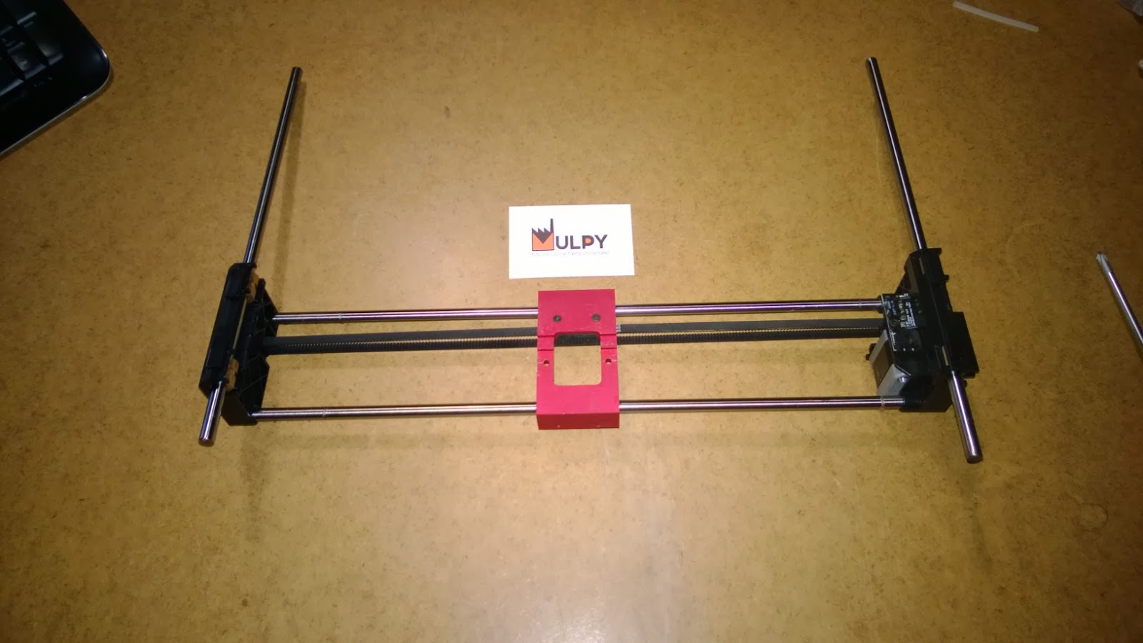
The only items required from the stock gantry are the rods, stepper motor, endstop circuit, wire harness and idler pulley... the rest of the components are supplied.

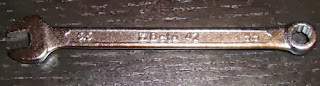
From a tool point-of-view... You will need a set of allen keys and a 5,5mm spanner.

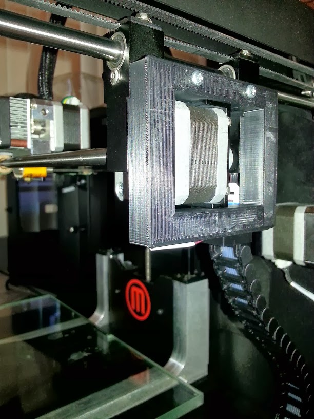
The first step in the assembly is to fit the stepper mount bracket to the stepper motor. Once fitted, the stepper and bracket are screwed onto the right x-end.

To be continued...


Carl

unread,
Oct 11, 2013, 2:10:57 PM10/11/13
to make...@googlegroups.com
The next step is to assemble the x-axis rods...

I start by removing the timing belt clips and standing the x-ends upside down... I loosen the set screws at the bottom of each of the x-ends... then add the extruder carriage bearings to the rods - which is VERY easy to forget to do! :-)

The rods simply push into their respective holes and are lined up to the end of the hole... lightly tighten the set screws once the rods are in place.

To be continued...


Carl

unread,
Oct 11, 2013, 3:37:32 PM10/11/13
to make...@googlegroups.com
At this stage... I have the rods with carriage bearings in place and connected to the x-ends.

The next step is to fit the timing belt.

I start by slipping the belt through the gap between the pulley and the x-end...

I then use the stock pulley idler with the supplied hub and two washers to start assembling the left side of the x-end.

The hub simply slides in and is held in place by the pressure from the timing belt.

You then add a washer...

The stock idler pulley (or a bearing pulley of your choice)...

I then loosen the set screw on the stepper side x-end and slide the x-end towards the idler pulley end to make it really easy to slip the timing belt into place...

I then slip the timing belt through the gap... 

add the other washer and push the hub into place.

With the timing belt now in place... I slide the stepper x-end back into position and lightly tighten the set screws.

The final step involved in stalling the timing belt is to tension the belt. This is done in the same way as on the stock setup... slide the stepper towards the outside and then tighten the four supplied screws to lock the stepper in position and hold the timing belt tension.

I then manually run the timing belt back and forward to make sure that it is running smoothly and nicely tensioned.

Carl

unread,
Oct 11, 2013, 5:42:11 PM10/11/13
to make...@googlegroups.com
Since the entire gantry is not in the machine... this is the perfect time to install the AluCarriage! :-)

Even if you do not have an AluCarriage... many of the points below will still be valid on the stock carriage. The exact same procedure applies to the AluCarriage Dual and the AluCarriage Single.

Due to the amount of vibration that the AluCarriage can experience during a print... the set screws do have a tendency to work loose - and even fall out! 

I have found that using a thread locking agent such as Loctite Blue or in my case... UHU Schraben Sicher... effectively eliminates the problem - whilst still allowing the screws to be removed if required in future.

I place a bit on a disposable paper plate and roll the screws through the solution - ensuring that the threads are adequately filled.

I alway check that the Nylon shims are firmly in position and then install the set screws on the AluCarriage, screwing them in to the point where the pointed tip touches the linear bearing - but does not move it...

If done correctly... the AluCarriage will have no up or down motion, move smoothly along the x-axis and sit only 0.2mm higher than the stock carriage - the thickness of the shims at their thinnest point.

I slide the AluCarriage to the left and right extremes of the x-axis - ensuring that there is no binding and the the AluCarriage lines up with the Alu-X-ends.

Note that I have not installed the timing belt into its clip yet... this is to make sure that the timing belt is not the cause of any binding at this stage. 

I then loosen the belt clip...

And slide the timing belt into place - I still DO NOT tighten the timing belt clip yet!

I slide the AluCarriage left and right - noting the effect on the belt at each extremity...

On the stepper motor side... the timing belt must line up perfectly with the pulley and the mounting position of the AluCarriage... if it does not...you will need to adjust the pulley alignment by loosening the pulley set screw and adjusting the alignment. 

The pulley idler should move back and forward firmly, but smoothly... if it does not it will require lubrication and/or adjustment of the timing belt tension.

Once complete... tighten the timing belt clip and recheck that everything runs smoothly.

At this stage the gantry is fully operational... almost there! :-)

To be continued...

Carl

unread,
Oct 11, 2013, 6:31:36 PM10/11/13
to make...@googlegroups.com
The next step is to lightly screw in the clips that will be tightened once the y-axis timings belts are in position.

At this stage it is still very easy to switch between the supplied linear ball bearings and the stock bearings by simply removing the screw on the side... slipping the current bearing out...slipping the other bearing in and locking it in place with the screw.

The next item to be installed is the x-endstop chip... still a bit of development to be done on this part... but it should work fine as is for now...

I have supplied a Nylon mounting pad to sit between the mounting point and the chip and a screw to mount it with... I am hoping to offer a printable case to house the chip in the near future...


After sliding in the y-axis rods... I am ready to install the gantry into my machine! :-)

To be continued...

Bottleworks

unread,
Oct 11, 2013, 8:03:29 PM10/11/13
to make...@googlegroups.com
It looks insanely nice.

Jake Dambergs

unread,
Oct 11, 2013, 11:14:28 PM10/11/13
to make...@googlegroups.com


On Friday, 11 October 2013 21:03:29 UTC-3, Bottleworks wrote:
It looks insanely nice.

+1!

Carl

unread,
Oct 12, 2013, 9:15:41 AM10/12/13
to make...@googlegroups.com
Needed to get some sleep! :-)

The next step... now that the gantry is assembled... is to install the gantry into the machine. The steps shown apply to a Replicator 2 and 2X... The y-axis rod mounting points are different on a Rep1... but the rest of the steps will still apply.

The side panels and build plate where removed earlier as part of uninstalling the stock gantry... I have lowered the z-axis to the lowest point and made sure that there are no obstacles or items that could get in the way of the installation of the gantry.

I take the entire gantry with y-axis rods attached, tilt it at an angle so that the front of the gantry points towards the bottom front of the case and the rear of the gantry points towards the top back of the case. I then slide it in to the case through the open side (I entered through the right side) ... this requires two hands - so unfortunately... I do not have photos for this step! :-)

The next step is to press fit the y-axis rods into their sockets on each of the top corners of the case. Being very careful to not damage any of the cables whilst doing this!

I start with the right rear socket...

   Then the right front socket...

Then the left rear socket...

And finally the left front socket...

Once all four ends of the y-axis rods are firmly in position... the gantry is technically re-installed! :-)

I then slide the x-axis back and forward long the y-axis...

I noticed binding on the y-axis bearings... I loosened the set screws holding the x-axis rods... and repeated the back and forward motion. This removed the binding.

Before tightening the set screws again... I lined the Alu-X-ends up with the plastic profile at the front of the y-axis. Once I was happy that the binding was gone and that the front aligned on both sides... I tightened the set screws.

With the Alu-X-ends still touching the front of the case... I proceeded to install the timing belts.

This is the trickiest part of the installation... Space and visibility are limited and it is critical that the timing belt still runs in line with the pulleys at either end. In future I will probably look at a redesigned clip to make this part of the installation a little easier! :-)

I start by tightening the rear timing belt clip on each side of the Alu-X-ends...

I then slide the x-axis towards the rear of the y-axis and tighten the front timing belt clips on both sides. 

After securely fitting the timing belts I repeatedly move the x-axis gantry back and forward to make sure that the timing belts are running straight and smoothly on both sides.

Almost there! :-)

To be continued...


Carl

unread,
Oct 12, 2013, 10:31:27 AM10/12/13
to make...@googlegroups.com
And finally... you need to reconnect the wiring harness for the x-axis endstop and stepper motor... 

The wiring harness enters through the bottom right corner... 

Connect the stepper...

Connect the endstop...

The additional threaded holes on the Alu-X-ends can act as mounting points for a cable tie...

The harness then connects to a screw on the top of the case and is held in place with a nut. I suggest removing the plastic profile used on the stock machine - but this is optional...

There are clips along the path to secure the cable in place...

Run the x-axis back and forward manually to make sure that the harness does not get caught on anything or have an excessive bend...

The gantry is now fully installed! :-)

Next... I will post a video of the x and y axis motion tests in jog mode...


Carl

unread,
Oct 12, 2013, 1:41:49 PM10/12/13
to make...@googlegroups.com
It's Alive! :-)

Here are the videos for...

X-Axis Jog Mode Test - http://youtu.be/SuvhR8vRPhY
Y-Axis Jog Mode Test - http://youtu.be/I-fGF96UR1U
Initial Print Test - http://youtu.be/S7ZY4m-gHd8

Now... I have to take it all apart again... reinstall the stock gantry... take photos of the disassembly procedure (which I forgot to do!)... then reinstall my Alu-X-ends using the supplied linear ball bearings for comparison... then I can start doing some proper print tests! :-)


Dan Newman

unread,
Oct 12, 2013, 2:13:56 PM10/12/13
to make...@googlegroups.com

On 12 Oct 2013 , at 10:41 AM, Carl wrote:

> It's Alive! :-)
>
> Here are the videos for…

1. Looks great!
2. Needs a musical score
3. What's with triggering the X endstop by thumb? X endstop needs to be a tad more
proud, or?

Dan

Carl

unread,
Oct 12, 2013, 2:30:21 PM10/12/13
to make...@googlegroups.com

1.  Looks great!
Thanks! I hope that everyone who bought one agrees!

2.  Needs a musical score
I agree! any suggestions for an appropriate score?

3.  What's with triggering the X endstop by thumb?  X endstop needs to be a tad more
    proud, or?
 
Without the extruder in place - in particular the stepper motor... there was nothing to trigger the switch. My thumb seemed like the appropriate solution at the time! :-) I am still hoping to have a printable case for the endstop... but the endstop does indeed work as it stands!

Gregory Sullivan

unread,
Oct 12, 2013, 2:51:56 PM10/12/13
to make...@googlegroups.com
When do they ship?

Carl

unread,
Oct 12, 2013, 3:07:33 PM10/12/13
to make...@googlegroups.com
When do they ship?

They will start shipping from Monday... a lot of orders to send... but I hope to have all current orders sent by the end of next week... loads of work to do on each set before final packaging and sending... but I am making good progress! :-) 

Carl

unread,
Oct 12, 2013, 3:27:42 PM10/12/13
to make...@googlegroups.com
The stock x-ends with bearings weigh in at 118grams... the Alu-X-ends - with all fittings and supplied bearing weigh in at 230grams...

John Armbruster

unread,
Oct 13, 2013, 11:48:31 AM10/13/13
to make...@googlegroups.com
Carl, will these instructions be supplied with the parts, or should I print out this thread? Also, are there instructions for the Alu-carriage update?

Carl

unread,
Oct 13, 2013, 12:21:49 PM10/13/13
to make...@googlegroups.com
By the end of this week... I am hoping to have all current orders sent and a pdf format instruction manual available for the AluCarriage and Alu-X-ends! :-)

John Armbruster

unread,
Oct 13, 2013, 1:05:50 PM10/13/13
to make...@googlegroups.com
Thanks...this whole project has been amazing to follow. Just waiting for the ends to arrive and I will do the carriage update simultaneously

Matthew Stonebraker

unread,
Oct 14, 2013, 10:24:20 AM10/14/13
to make...@googlegroups.com
Looks beautiful and functional, Carl! I think the next plastic part of the printer that you should replace with metal is the filament! ;)

Robo

unread,
Oct 14, 2013, 10:41:12 AM10/14/13
to make...@googlegroups.com
This looks amazing and I can't wait to get them installed.  It's hard to guess from looking at the videos, but does this design provide clearance for extruder upgrades that have the thumb tab sticking out the side?  Or would it be better to get the 3in1 which looks to be flush against the left side?

Jetguy

unread,
Oct 14, 2013, 12:00:34 PM10/14/13
to make...@googlegroups.com
Gotta think in 3D man. The typical extruder finger levers barely extend over the carriage end and keep in mind the motor sits roughly centered in line with the X rods. The limit switch is above it and trips from the motor hitting it.
The lever in question is far above the limit switch in the X plane of motion.

Robo

unread,
Oct 14, 2013, 1:13:46 PM10/14/13
to make...@googlegroups.com
That's what I'd gathered from looking at the bot as it currently is, just wanted to avoid any surprises.  I have the Karas extruder upgrade which has been nothing but great.  

Carl

unread,
Oct 18, 2013, 12:35:10 PM10/18/13
to make...@googlegroups.com
It has been a very busy week... but I am happy to say that I have now sent all of the Alu-X-end orders received to date! :-)

The next thing on my list is to complete and upload the installation guide - which I hope to have completed by the end of this weekend.

I have posted two videos on youtube of the initial test prints... testing is still ongoing...

The first video uploaded today shows my first acceleration test print... Printing PLA and a starting speed of 60mm/s and doubling it to 120mm/s. The second video shows my first full print in PLA at 120mm/s - 0.1mm. 

The prints are done using my custom idler pulley - which I am still perfecting... they also show my T-Shaped Heater Block and AluCarriage Single.


Pascal POECK

unread,
Oct 18, 2013, 2:44:19 PM10/18/13
to make...@googlegroups.com
Hi Carl,

I received mine this morning, excellent job like for the carriage. I will try to install them this week-end if I have time enough. Do you think it's better to wait for your instructions or the details posted here are enough and correct?
I saw that you remove the lateral fan so I suppose you print only in Nylon? Correct?
And wat about your T-Shaped? I didn't find any information on this but I missed probably a post...

Thanks for everything, I'll keep you posted ;)
PascalP

Carl

unread,
Oct 18, 2013, 3:35:45 PM10/18/13
to make...@googlegroups.com
It is a fairly easy to install... but I am trying to offer a detailed set of instructions to help with some of the things to watch out for during the installation - I am busy with it at the moment and hope to have it out by the end of this weekend.

If you are going to do the installation before I finish the guide, there are a few things that are very important...
  1. Make sure to unplug your machine and remove your extruder.
  2. Slide the timing belts off of both x-ends - simply pull the timing belts towards the build plate so that the are no longer clipped into the stock x-ends - you do not have actually remove the y-axis timing belts from the machine!
  3. Unplug the wiring harness on the stepper motor side and make sure that it is no longer connected to the right hand x-end - make sure it is safely out of the way!
  4. The y-axis rods on the Rep2 / 2X are press-fitted into plastic profiles on each corner. To remove them you need to push down to pop them out of their sockets... be VERY careful when doing this to make sure that you do not damage any of the cables that are routed around them.
After you have removed the stock gantry... the majority of the work can be done outside of the machine as explained earlier in this thread.

Any major concerns or questions... just post here or send me an email...

The newest video that I have posted has the active cooling fan installed.

Been to busy to post on my T-Shaped Heater Block... I will post more information about it later... I am very happy with how well it actually works though! :-)

Pascal POECK

unread,
Oct 18, 2013, 3:44:53 PM10/18/13
to make...@googlegroups.com
Excellent, I will try tomorrow, can't wait ;)


2013/10/18 Carl <cpra...@gmail.com>

--
You received this message because you are subscribed to a topic in the Google Groups "MakerBot Operators" group.
To unsubscribe from this topic, visit https://groups.google.com/d/topic/makerbot/HFWfSzZ_GGw/unsubscribe.
To unsubscribe from this group and all its topics, send an email to makerbot+u...@googlegroups.com.
For more options, visit https://groups.google.com/groups/opt_out.

AGG

unread,
Oct 18, 2013, 6:38:19 PM10/18/13
to make...@googlegroups.com
I almost installed the aluminum x-ends on my machines but it looks the only big problem for me is that I cannot find 5.5 mm wrench. A have tons of tools but unfortunately not this one. Be sure to have one before starting because you will not be able to complete the installation. I'm looking for another set of screws but 3mm thread is also a problem in Canada. Also the original bearings are definitely less noisy than the supplied one. The end stop board needs to be trimmed on the bottom side with wire cutters in order to have more flat surface.

Jake Dambergs

unread,
Oct 18, 2013, 6:51:11 PM10/18/13
to make...@googlegroups.com
5.5mm hex wrench via home depot:  http://www.homedepot.ca/product/13-piece-metric-w-handle/967044

Otherwise, fastenall will undoubtedly have a replacement screw but you’ll probably have to buy a box of them.

On Oct 18, 2013, at 7:38 PM, AGG <as...@assen1969.com> wrote:

I almost installed the aluminum x-ends on my machines but it looks the only big problem for me is that I cannot find 5.5 mm wrench. A have tons of tools but unfortunately not this one. Be sure to have one before starting because you will not be able to complete the installation. I'm looking for another set of screws but 3mm thread is also a problem in Canada. Also the original bearings are definitely less noisy than the supplied one. The end stop board needs to be trimmed on the bottom side with wire cutters in order to have more flat surface.

AGG

unread,
Oct 18, 2013, 7:22:13 PM10/18/13
to make...@googlegroups.com
Sorry, my English is not my force. I mean this type:


AGG

unread,
Oct 18, 2013, 8:13:09 PM10/18/13
to make...@googlegroups.com
OK, done by using standard computer screws 3 mm, screwdriver and 5 mm holes on the top of the frame for easy access to the screws. It takes less than an hour to complete the installation. One additional issue is that nothing can stop the hub for the pulley idler to go out and that happened during my first print. I will print kind of PLA cube part to block it on place but it was better to make a hole with thread and to hold it by screw and metal plate before the final installation.
The rest is exceptional quality of the aluminum parts as usual  perfectly done by Carl. Thank you!

Carl

unread,
Oct 19, 2013, 11:19:29 AM10/19/13
to make...@googlegroups.com
I would love to see some photos! :-) Have you been able to do a print yet?

I am finding the linear ball bearing are considerably quieter after a couple of hours of printing... They seem to need a bit of bedding in...

The idler pulley hub shouldn't work loose... the pressure from the belt tension should keep it firmly in place... is your belt maybe too loose or too tight?

Pascal POECK

unread,
Oct 19, 2013, 1:09:47 PM10/19/13
to make...@googlegroups.com
You want to see pictures? Here we go, step one done : remove the extrudeur. That was the easiest part... Let's go to the next step ;)

Pascal POECK

unread,
Oct 19, 2013, 1:24:28 PM10/19/13
to make...@googlegroups.com
Timing Belt : easy
Unplug wiring hardness : easy
Removing Y-axes rod : easy but be carefull

Let's go further ;)

Pascal POECK

unread,
Oct 19, 2013, 2:22:13 PM10/19/13
to make...@googlegroups.com
So far so good...

Fixing the stepper motor : easy
Assemble the X-axes rods : easy

AGG

unread,
Oct 19, 2013, 2:37:36 PM10/19/13
to make...@googlegroups.com


On Saturday, October 19, 2013 11:19:29 AM UTC-4, Carl wrote:
I would love to see some photos! :-) Have you been able to do a print yet?

Yes, I printed a few things but I still have a problem with the hub. I will do again the installation to hold the hub properly. My timing belt is tight because I print small parts and I need to have minimal backlash. Also I have to design a cable chain for the x-axis cable and then I will post photos of the complete installation. 

Pascal POECK

unread,
Oct 19, 2013, 3:00:02 PM10/19/13
to make...@googlegroups.com
Seem's to be good for the moment ;-)

JT

unread,
Oct 19, 2013, 3:06:32 PM10/19/13
to make...@googlegroups.com
I am one of those who has ordered the aluminum x-ends for my R2.  But I just wanted to post the attached picture which shows the advantage of using aluminum parts.  Due to still another x-axis cable problem, I had the maximum blob produced when I did a large print and went away, assuming it would be fine.  Extruded PLA surrounded everything.  Without Carl's excellent aluminum carriage, I would have ruined the original plastic carriage, trying to remove the blob.  Melted plastic that had hardened on the aluminum just came right off.
IMG_0405[1].jpg

Pascal POECK

unread,
Oct 19, 2013, 4:48:14 PM10/19/13
to make...@googlegroups.com
Done and the first print is ongoing :D
Thanks again to Carl, this modification is easy to install but you need to take your time to be sure to not make any misstake ;-)

You can see a video of my first try here : http://youtu.be/spIrarApXu8 

Ill keep you update when the print is finished but it may take a while ;-)

Pascal POECK

unread,
Oct 19, 2013, 4:49:06 PM10/19/13
to make...@googlegroups.com
Just to clarify that the printer is in a noisy room so the sounds come not only from the printer ;)

Carl

unread,
Oct 20, 2013, 8:08:25 AM10/20/13
to make...@googlegroups.com
Thanks! It is awesome to finally see the first of these being installed! :-)

AGG

unread,
Oct 20, 2013, 6:13:32 PM10/20/13
to make...@googlegroups.com
Just a few pictures before completing the installation. It needs more work and I'll postpone it for the next weekend.


AGG

unread,
Oct 21, 2013, 2:30:51 PM10/21/13
to make...@googlegroups.com
One more aluminum plate with a screw and the hub will never go out by itself. Just need to do this once again for the second printer and I'm done. I used this opportunity to fix my X-axes cables with a high flex cable in a cable chain and they are good for life time.


Steve Johnstone

unread,
Oct 21, 2013, 2:34:07 PM10/21/13
to make...@googlegroups.com
WOW, they certainly look the part.

Nice job on the installation.

Carl

unread,
Oct 21, 2013, 6:20:27 PM10/21/13
to make...@googlegroups.com
The Alu-X-ends installation guide is now available! :-)

The pdf is located in the 'Installation' tab on the Alu-X-ends page on my website.

It has been surprisingly difficult to explain the procedure... I have tried to include as many pictures and make it as logical as possible... installation should not take longer than an hour... at this stage, I am able to do it in around 15 minutes! :-)

production

unread,
Oct 25, 2013, 6:58:03 PM10/25/13
to make...@googlegroups.com
I have been looking at your x end replacement parts and I really like the design. Just wondering how hard would it be to make a device to hold the stepper motor and then be able to adjust this with a screw or 2 so as to make a belt tension system?

On Friday, August 23, 2013 2:29:48 AM UTC+10, Carl wrote:
If anyone interested in replacement Aluminium X ends... I am currently taking pre orders for a prototype run! :-)

Jetguy

unread,
Oct 25, 2013, 7:15:44 PM10/25/13
to make...@googlegroups.com
There really is no need for that. The motor is already in slots.
Trust me, you need to worry more about the Y axis than this. The X is the most accurate part of the system even before this part.
The Y axis is the disaster because of indirect drive. Just trying to focus your efforts.

Carl

unread,
Oct 25, 2013, 7:44:10 PM10/25/13
to make...@googlegroups.com
During my initial concept design... I was shocked at just how loose the timing belt on the x-axis can be - print speed dependant - before it skipped steps. I do not believe that the timing belt needs to be too tight on the x-axis... just tight enough to not skip steps at the required speed - which the current design allows for.

I have, however, designed a 'system' logic into the Alu-X-ends by adding the threaded holes on the core left and right elements.... This allows either the idler pulley or stepper motor brackets to be modified and replaced in future without replacing the entire mechanism.

I am also currently designing replacements for the plastic parts that hold the y-axis rods in place - specifically for the Replicator 2 and 2X. These will hopefully allow the belt tension to be adjusted and offer extra strength to support the additional weight of gantry.

I cannot wait to get feedback on the initial prototype units sent... the postal system feels REALLY slow at the moment! :-)
    

Robo

unread,
Oct 25, 2013, 8:15:29 PM10/25/13
to make...@googlegroups.com
Carl,

I received my X-ends today and they look fantastic!  Unfortunately, I failed to plan ahead and have to order a 5.5mm wrench, which I can't get locally.  Also, I seem to have lost one of the set screws that hold the rods. It appears that I did receive them all based on the photo I took, but it must have come out while I was showing off my fancy new parts.  (still searching for it, haha)  Can you tell me the specs of those screws so I can order some?  

At any rate, I will be sure to post some photos and feedback once I get them installed.  Also thrilled to hear you're working on replacements for those corner brackets - I was already thinking, hmm, these are made of plastic...

Carl

unread,
Oct 25, 2013, 8:32:17 PM10/25/13
to make...@googlegroups.com
The supplied set screws are M3 x 4mm - Cup Point. As a temporary measure... any M3 screw / set screw will do the job until you can get replacements.

I had to use a hex head due to the limited space between the frame and the top of the x-ends. I did not think anyone would be keen on drilling a hole in the top of the frame to access a allen key screw! :-)

Send me an email if you have trouble getting the 5.5mm spanner / set screws...


AGG

unread,
Oct 25, 2013, 8:55:55 PM10/25/13
to make...@googlegroups.com
>> I did not think anyone would be keen on drilling a hole in the top of the frame to access a allen key screw! :-)

Here is America - very limited metric system tools in the shops. I came from Europe but even there it is not easy also to get exactly 5.5 mm. Anyway, I've disassembled  completely my printer and had to find fast solution to complete the installation.

Robo

unread,
Oct 25, 2013, 9:03:31 PM10/25/13
to make...@googlegroups.com
Thanks for your quick response. I can get those exact screws and a 5.5mm from McMaster-Carr here in the US. Easily the best place to get anything tool related.  I'm not worried about the limited space involved in tightening the belt clips, it's certainly better than drilling the frame!

Robo

unread,
Oct 29, 2013, 8:12:08 PM10/29/13
to make...@googlegroups.com
I've got my wrench and screws now and will be installing these in the next day or two.  Do you have a recommendation or preference between the stock bushings and the ball bearings for the y-axis rods?

Carl

unread,
Oct 29, 2013, 8:22:37 PM10/29/13
to make...@googlegroups.com
I recommend installing them with the linear ball bearings... they were noisier at first... but after around 20 hours of printing they seem to have bed in and I hardly notice that they are there anymore! :-)

John Armbruster

unread,
Nov 2, 2013, 1:48:57 PM11/2/13
to make...@googlegroups.com
This setup looks excellent, is there an upload on thingiverse? Can you expand on the installation?

BruceA

unread,
Nov 2, 2013, 8:41:28 PM11/2/13
to make...@googlegroups.com
John
Please could you post the Thingiverse link I lost the cable chain thing and can not locate it again. thanks

John Armbruster

unread,
Nov 2, 2013, 8:56:46 PM11/2/13
to make...@googlegroups.com
do you have a link to the bearings? BTW, just picked them up yesterday...fabulous!

AGG

unread,
Nov 2, 2013, 11:57:31 PM11/2/13
to make...@googlegroups.com
On Saturday, November 2, 2013 8:41:28 PM UTC-4, BruceA wrote:
John
Please could you post the Thingiverse link I lost the cable chain thing and can not locate it again. thanks

I didn't post this project on Thingiverse because all parts are designed just for Aluminium X ends in combination with a cable from the Hi-flex Cable Upgrade kit which is no longer available:


I didn't install it when I bought this kit and now I used only the cable. Also I didn't finish with the parts. There is a need of another part clipped on the X rods to hold also the x-end cable. No time at the moment to complete everything.
 

Carl

unread,
Nov 3, 2013, 11:24:12 AM11/3/13
to make...@googlegroups.com
Great to hear that these have started arriving! :-) 

I would love to get feedback - positive or negative - I am always looking for ways to make the components better!

Robo

unread,
Nov 6, 2013, 8:34:51 PM11/6/13
to make...@googlegroups.com
Carl,

Now I've got the X-Ends installed and I have some comments for you. In addition to the X-Ends I have also been using the Alucarriage to great success.  In all I think the X-Ends are a fantastic upgrade. 

At first I was terrified of snapping the Y axis rods out of the plastic brackets, but it was pretty easy and required less force than taking the MBI carriage off the bushings when I did the Alucarriage a while back.  

I spent several different sessions checking the tension of all the screws and fittings and making sure the gantry was flush on both sides toward the front.  In my opinion this probably requires the most emphasis as the entire system needs to remain as accurate as possible, and this upgrade is a major change to the system.

The nylon(?) mounting piece for the X-axis switch, as you've said, could use some improvement.  After expanding the hole to fit the screw I found that the piece was just kind of a separator between the board and the aluminum. While it's fitted firmly, I think it might help to have a small, raised cylinder section around the hole to help with the offset I'm seeing.  The underside of the board has a lot of solder that makes it taller than it first appears, so there is an offset between the circuit board, mount, and aluminum, and the mount just sort of floats in between.  The raised back of the mounting piece is good, as it keeps the board from moving around the screw.

The Y-axis mounting pieces are indeed a challenge to screw in, but I wonder if they could be longer to cover the entire top of the x-end.  Since there are screw holes on both sides of the X-ends, couldn't there be two screws that would ensure the plate holds the belt down flat?  I realize this would be a real challenge to get the screws in under the tight space.  Currently the plates tend to sit at an angle on top of the belt when screwed down, and while it might hold the belts just fine, it is rather off-putting to see the clips angled this way.  If one were to also replace the corner brackets, there might be a better opportunity to fix the y-belts to the x-ends than this method... ;)

I haven't had any issues yet with the rod in the left side hub, but as has been stated by others, I might feel a little safer if there was something to hold it in place.  

The cables for the x-axis switch and the motor are currently just hanging, as I've seen some other users do.  These are still just the stock cables in my bot - The only thing that hasn't been upgraded at this point.

I've done a lot of jog tests and am currently printing some leveling discs at slow speed.  Once I'm confident of everything I will post some images.  Thank you for another high quality upgrade that improves the bot and looks awesome at the same time!

Carl

unread,
Nov 13, 2013, 12:07:12 PM11/13/13
to make...@googlegroups.com
Thanks for the feedback Robo! It is really appreciated! :-)

Robo

unread,
Nov 14, 2013, 8:32:31 PM11/14/13
to make...@googlegroups.com
I forgot to add one thing.  Because the Alucarriage and X-ends raise the axis a bit higher than the stock configuration, it's a good idea to have some spring spacers for your build plate mounts ready before installing.  I also have Bottleworks's excellent z-arms and HPB, so I had a few of these already printed.  The combination of all these mods meant that I had to use the spacers to retain enough spring tension under the plate to reach the nozzle for leveling.  (He also points out to move the z endstop switch as necessary). With your mods alone I think this effect would be less pronounced, but I suppose a lot of the users who are inclined to do these upgrades have some or all of these kits anyway.  I know you don't officially collaborate, but your collective efforts really make the bot sing.

I still intend to post pics during a print - so far everything's working out to be very smooth and stable.

Jay

unread,
Nov 20, 2013, 1:25:55 PM11/20/13
to make...@googlegroups.com
Robo,

Like you I have Bradley's arms installed. There are printable spacers but I found steel washers are better. I install one top and bottom of the springs (M3 washer?...not at home currently). That provides a solid base so the springs compress together. I noticed that there is a countersink on the build plate that the springs fit into...and some seat fully and some 'almost' fit fully. Using the small washers you get an equal compression distance on all 3 springs....

Jay

Robo

unread,
Nov 21, 2013, 6:32:27 PM11/21/13
to make...@googlegroups.com
Thanks for the tip, that's a good idea.  McMaster-Carr has some 'extra thick' M3 washers that I'm looking at. My only concern is that they give a range of thickness, so I'm not sure if a given pack will have identical pieces. Can you tell me more about the ones you're using?

Jay

unread,
Nov 22, 2013, 3:38:15 PM11/22/13
to make...@googlegroups.com
Robo,
Hmm...to be honest mine were el-cheap stamped ones I had left over from some assembly kits....this works if your springs have lost their...springiness. If you have nice strong ones I would just put them between the countersink and the spring. If they're strong and you use 2 it may be harder to tighten down. I remember I tried it both ways but the bot I put them had almost a thousand hours and I got this almost 9 months ago...

Jay

Carl

unread,
Nov 23, 2013, 5:40:39 AM11/23/13
to make...@googlegroups.com
Thank you to everyone that has provided feedback on the initial prototypes!

I will start taking pre-orders for the next batch of Alu-X-ends from today and hope to have them ready to send in the next 3-4 weeks - if you would like a specific colour please place your order soon! :-)

Scott Goldthwaite

unread,
Nov 24, 2013, 7:38:20 AM11/24/13
to make...@googlegroups.com
Now that these aluminium x-ends have been out for a little while, I'd like to hear about the benefits people have seen.  This upgrade seems pretty nice, but does it make a noticeable difference in the performance of the Replicator?  Please share your experiences.
It is loading more messages.
0 new messages