Curved plywood dome

JRal


homespun
--
--
You received this message because you are subscribed to the "Geodesic Help" Google Group
--
To unsubscribe from this group, send email to GeodesicHelp...@googlegroups.com
--
To post to this group, send email to geodes...@googlegroups.com
--
For more options, visit http://groups.google.com/group/geodesichelp?hl=en
---
You received this message because you are subscribed to the Google Groups "Geodesic Help Group" group.
To unsubscribe from this group and stop receiving emails from it, send an email to geodesichelp...@googlegroups.com.
For more options, visit https://groups.google.com/groups/opt_out.

TaffGoch
John Ralphs


--
--
You received this message because you are subscribed to the "Geodesic Help" Google Group
--
To unsubscribe from this group, send email to GeodesicHelp...@googlegroups.com
--
To post to this group, send email to geodes...@googlegroups.com
--
For more options, visit http://groups.google.com/group/geodesichelp?hl=en
---
You received this message because you are subscribed to a topic in the Google Groups "Geodesic Help Group" group.
To unsubscribe from this topic, visit https://groups.google.com/d/topic/geodesichelp/90sZTu8DquI/unsubscribe?hl=en.
To unsubscribe from this group and all its topics, send an email to geodesichelp...@googlegroups.com.
John Ralphs


TaffGoch
I really rate laser cutters, I think they are more useful than 3D printers. I am lucky enough to have one at work. I am seriously thinking about building or buying one. I also made a cardboard prototype using it.
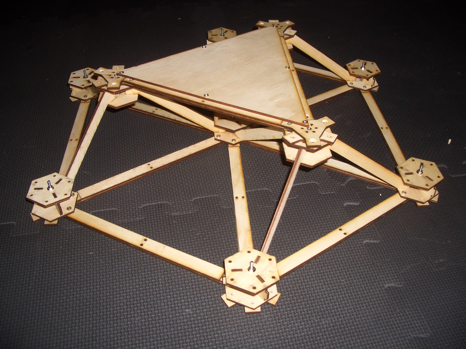
Those pictures are actually my second attempt, and yes the struts have been glued onto a curved jig.
Here is how I constructed the hub stand offs. I found these to be very strong and simple to construct compared to my original idea of the S shaped laminated stand offs (will show in next post).
The centre part is slid over the end piece by leveraging it out on a butter knife while pushing the whole thing together.
All four centre pieces need to be lifted at the same time when sliding the pieces together. pull the knives out and the whole thing clicks into place. No glue!

lpaniceres
I´ll real love to make one!
Could you help me with the plans?
thanks!
John Ralphs
Hi lpaniceres
This is still a work in progress, I am still working on the detail on this scale model in the pictures. I am doing the detail of windows, doors and floors, this significantly adds to the complexity. My estimate is there will be about 500 unique parts to a full dome.
I eventually plan to use the design to build a 12 meter dome that can be lived in.
I am still debating whether to release the cut files as I have put several hundred hours of work into the drawings.
If you want to do your own cutting files the dimensions are based around arc lengths along great circles between vertices on a standard geodesic dome. From the pictures on this post you should be able to figure out the rest of the construction methods. I am on about iteration 5 on the prototyping so I will have saved you a bit of time anyway.
At any rate I won't be releasing any files until I am 100% happy the design. This will be a way off as I still have many many hours of work to go. The precision cut nature of the build means all the design work must be done up front.
--
You received this message because you are subscribed to the "Geodesic Help" Google Group
--
To unsubscribe from this group, send email to GeodesicHelp...@googlegroups.com
--
To post to this group, send email to geodes...@googlegroups.com
--
For more options, visit http://groups.google.com/group/geodesichelp?hl=en
---
You received this message because you are subscribed to a topic in the Google Groups "Geodesic Help Group" group.

Dick Fischbeck
John Ralphs
--
JRal


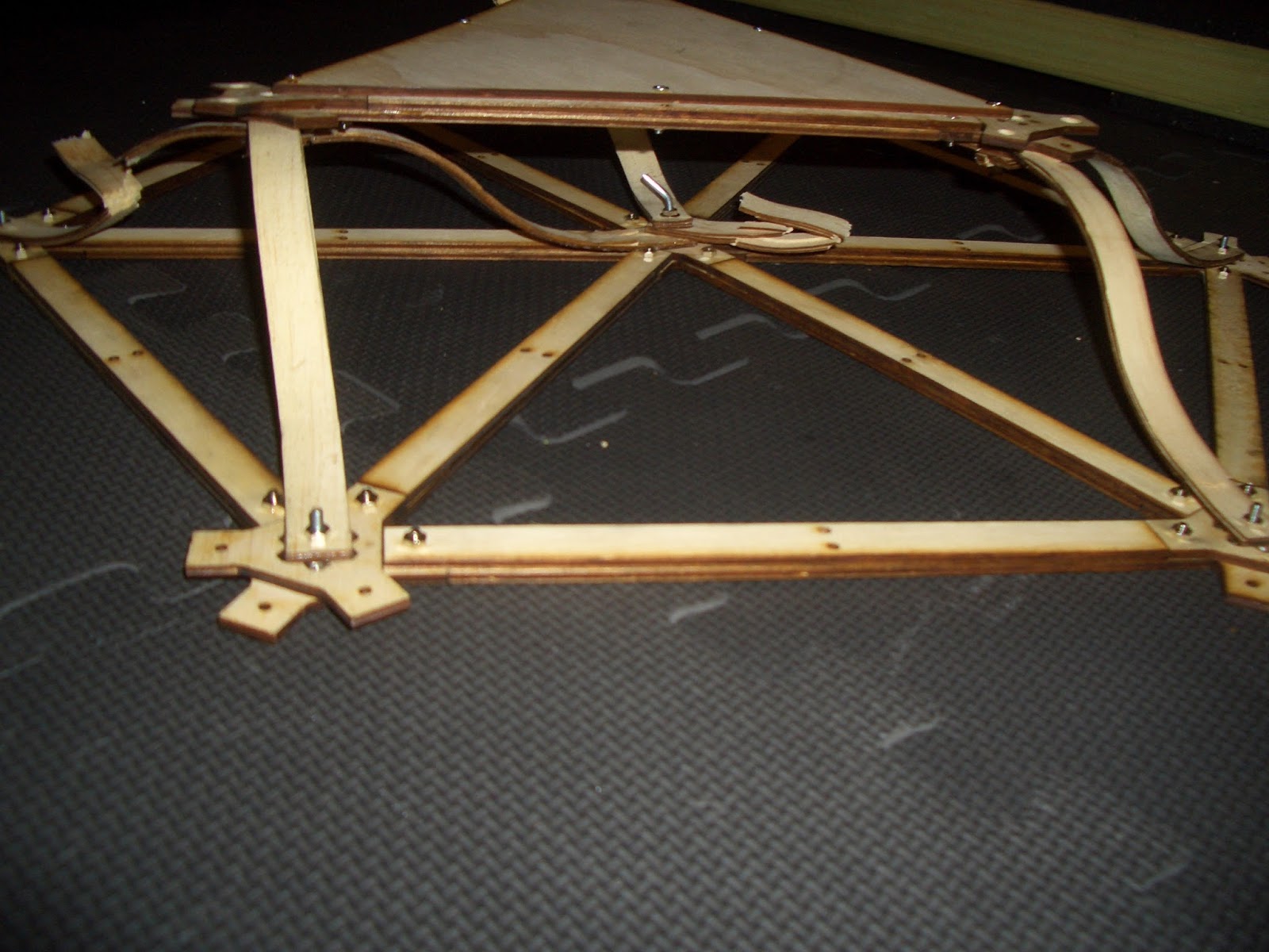
The next piece was my first attempt, the curved struts were my initial solution of how to attach the diagonals, this one failed at 35 Kg.
TaffGoch
_____________________
Now, what about how a floor/beam really works. Only the ends should be supported, with weight applied in the center. This will produce maximum compression along the top surface, and max tension along the bottom.
When tested in this manner, you will see what portion "gets pulled to pieces" (tension failure, typically, somewhere in bottom-most components.) I presume this is next, in your testing regimen?
John Ralphs
Hi Taff, that is my thoughts exactly. My next test will be two cells wide at the bottom one cell wide at the top. And 1.5 meters long (Distance between the centre of the dome where I plan to put a single support and the edge where I plan to put the rest of the supports). Then I will test the entire circle of the floor. Hopefully it gets stronger each time the number of cells go up.
I want it to withstand a point load of 140 kg. ( pressing on one cell, I use a 100 mm diameter footprint. Cells are 250mm along their edges)
I have thought of an alternative way of doing the horizontal struts that requires less gluing and screwing. I will also test this.
I still haven't figured out a good way to mount the frame on supports. I was thinking screw piles would be a good way to go but then I need way attach the frame to the piles that allows for difference in bolt angles / heights at the top of the pile and large tolerances from not being able to accurately place them in the ground.
What do you think?
--
TaffGoch
JRal
JRal


The other part I have been working on is the base ring, this took more time to design than the rest of the struts (doors and windows not included, they are even more complex), I figured out a formula so that I can calculate the arc of the ring when flattened out, this makes the bottom of the dome parallel with the ground instead of a series of five inverted arches.


On Friday, May 17, 2013 8:38:57 PM UTC+10, JRal wrote: