Initial H8 Backplane test!

norberto...@koyado.com
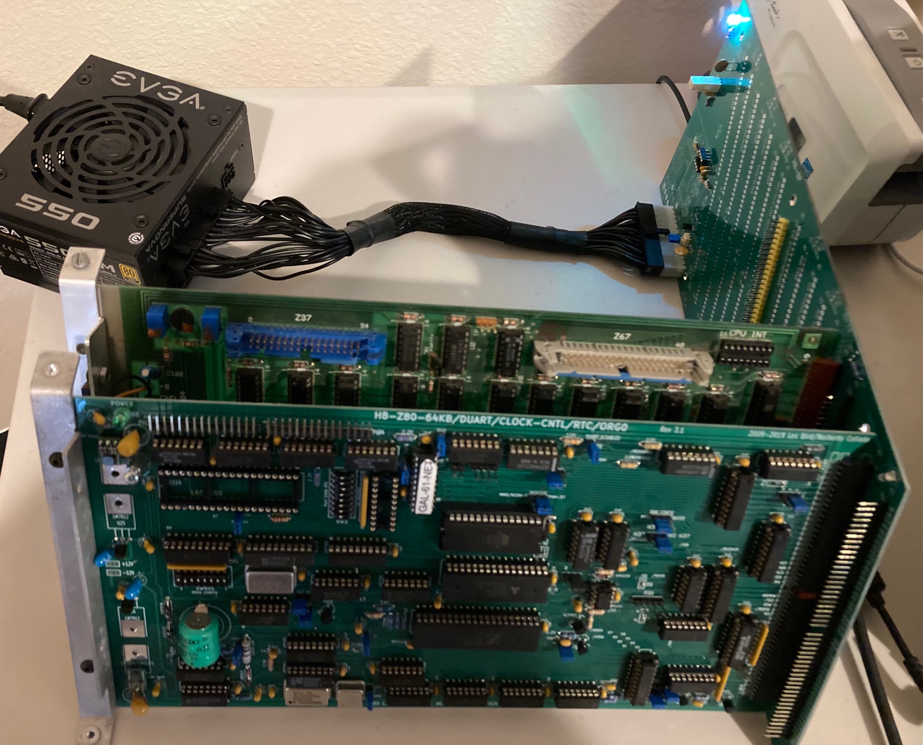
I decided to power up the new H8 backplane to test voltages on the H8 bus. On power-on the power supply turns on and then it shutdown. It seems that I do not have minimum load on the ATX PSU to keep it on. The only voltage I get is the Standby voltage along with it’s LED. I do have the “blue” jumper installed to keep it “on” all the time.
Do anyone knows the minimum A load to keep it running? Not sure if minimum load is on the +5 or +3.3 voltage rails. I hope I do not have a bad PDU as it was expensive to buy.
Thanks,
Norberto ☹
Sent from my iPhone

Steven Feinsmith
Sent: Saturday, July 10, 2021 1:22:15 AM
To: se...@googlegroups.com <se...@googlegroups.com>
Subject: [sebhc] Initial H8 Backplane test!
You received this message because you are subscribed to the Google Groups "SEBHC" group.
To unsubscribe from this group and stop receiving emails from it, send an email to sebhc+un...@googlegroups.com.
To view this discussion on the web visit https://groups.google.com/d/msgid/sebhc/005301d7754b%248ba878f0%24a2f96ad0%24%40koyado.com.
norberto...@koyado.com
Thanks for the link, very detailed information. Let me also check the PSU specs as well.
Norberto
To view this discussion on the web visit https://groups.google.com/d/msgid/sebhc/BL0PR03MB406766B94455790D709DE8BBAC179%40BL0PR03MB4067.namprd03.prod.outlook.com.

Pat OConnor
Thanks for the link, very detailed information. Let me also check the PSU specs as well.
Norberto
From: se...@googlegroups.com <se...@googlegroups.com> On Behalf Of Steven Feinsmith
Sent: Friday, July 9, 2021 10:32 PM
To: se...@googlegroups.com
Subject: Re: [sebhc] Initial H8 Backplane test!
From: se...@googlegroups.com <se...@googlegroups.com> on behalf of norberto...@koyado.com <norberto...@koyado.com>
Sent: Saturday, July 10, 2021 1:22:15 AM
To: se...@googlegroups.com <se...@googlegroups.com>
Subject: [sebhc] Initial H8 Backplane test!
I decided to power up the new H8 backplane to test voltages on the H8 bus. On power-on the power supply turns on and then it shutdown. It seems that I do not have minimum load on the ATX PSU to keep it on. The only voltage I get is the Standby voltage along with it’s LED. I do have the “blue” jumper installed to keep it “on” all the time.
Do anyone knows the minimum A load to keep it running? Not sure if minimum load is on the +5 or +3.3 voltage rails. I hope I do not have a bad PDU as it was expensive to buy.
Thanks,
Norberto ☹
<image001.jpg>
Sent from my iPhone
--
You received this message because you are subscribed to the Google Groups "SEBHC" group.
To unsubscribe from this group and stop receiving emails from it, send an email to sebhc+un...@googlegroups.com.
To view this discussion on the web visit https://groups.google.com/d/msgid/sebhc/005301d7754b%248ba878f0%24a2f96ad0%24%40koyado.com.
--
You received this message because you are subscribed to the Google Groups "SEBHC" group.
To unsubscribe from this group and stop receiving emails from it, send an email to sebhc+un...@googlegroups.com.
To view this discussion on the web visit https://groups.google.com/d/msgid/sebhc/BL0PR03MB406766B94455790D709DE8BBAC179%40BL0PR03MB4067.namprd03.prod.outlook.com.
--
You received this message because you are subscribed to the Google Groups "SEBHC" group.
To unsubscribe from this group and stop receiving emails from it, send an email to sebhc+un...@googlegroups.com.
To view this discussion on the web visit https://groups.google.com/d/msgid/sebhc/005d01d7754f%240df51270%2429df3750%24%40koyado.com.
norberto...@koyado.com
Thanks! The original Heathkit backplane as a 150 ohm 2W resistor to discharged the big blue capacitor. Let me buy a 100 ohm 2W instead to get the 50ma range.
Norberto
To view this discussion on the web visit https://groups.google.com/d/msgid/sebhc/15A6915E-1C8D-4E52-8AAE-469810B2C051%40gmail.com.

Terry Gulczynski
the power supply, simply connect a spinny-disk IDE drive - it's more
than enough load to meet any minimum the power supply might require.
(We all have a few IDE drives on a shelf somewhere, right?)
Terry
On 7/10/2021 3:23 AM, norberto...@koyado.com wrote:
> Thanks! The original Heathkit backplane as a 150 ohm 2W resistor to
> discharged the big blue capacitor. Let me buy a 100 ohm 2W instead to
> get the 50ma range.
>
> Norberto
>
> *Pat OConnor
> *Sent:* Friday, July 9, 2021 11:45 PM
> *To:* se...@googlegroups.com
> *Subject:* Re: [sebhc] Initial H8 Backplane test!
> Many years ago I used an ATX supply on my bench. As I recall, witch is
> questionable the way my memory is, you needed a 50 ma load on the 5 or
> 12 line. I hope this helps.
>
> Pat
>
> Sent from my iPhone
>
>
>
> On Jul 10, 2021, at 1:47 AM, norberto...@koyado.com
>
>
>
> Thanks for the link, very detailed information. Let me also check
> the PSU specs as well.
>
> Norberto
>
> <se...@googlegroups.com <mailto:se...@googlegroups.com>> *On Behalf
> Of *Steven Feinsmith
> *Sent:* Friday, July 9, 2021 10:32 PM
> *To:* se...@googlegroups.com <mailto:se...@googlegroups.com>
> *Subject:* Re: [sebhc] Initial H8 Backplane test!
>
> https://www.intel.com/content/dam/www/public/us/en/documents/guides/power-supply-design-guide-june.pdf
> <https://www.intel.com/content/dam/www/public/us/en/documents/guides/power-supply-design-guide-june.pdf>
>
> Get Outlook <https://aka.ms/sdimjr> for iOS
>
> ------------------------------------------------------------------------
>
> *From:*se...@googlegroups.com <mailto:se...@googlegroups.com>
> <se...@googlegroups.com <mailto:se...@googlegroups.com>> on behalf
> of norberto...@koyado.com <mailto:norberto...@koyado.com>
> <norberto...@koyado.com <mailto:norberto...@koyado.com>>
> *Sent:* Saturday, July 10, 2021 1:22:15 AM
> *To:* se...@googlegroups.com <mailto:se...@googlegroups.com>
> <se...@googlegroups.com <mailto:se...@googlegroups.com>>
> *Subject:* [sebhc] Initial H8 Backplane test!
> I decided to power up the new H8 backplane to test voltages on the
> H8 bus. On power-on the power supply turns on and then it shutdown.
> It seems that I do not have minimum load on the ATX PSU to keep it
> on. The only voltage I get is the Standby voltage along with it’s
> LED. I do have the “blue” jumper installed to keep it “on” all the time.
>
> Do anyone knows the minimum A load to keep it running? Not sure if
> minimum load is on the +5 or +3.3 voltage rails. I hope I do not
> have a bad PDU as it was expensive to buy.
>
> Thanks,
>
> Norberto ☹
>
> <image001.jpg>
>
>
>
> Sent from my iPhone
>
> --
> You received this message because you are subscribed to the Google
> Groups "SEBHC" group.
> To unsubscribe from this group and stop receiving emails from it,
> send an email to sebhc+un...@googlegroups.com
> https://groups.google.com/d/msgid/sebhc/005301d7754b%248ba878f0%24a2f96ad0%24%40koyado.com
> --
> You received this message because you are subscribed to the Google
> Groups "SEBHC" group.
> To unsubscribe from this group and stop receiving emails from it,
> send an email to sebhc+un...@googlegroups.com
> <https://groups.google.com/d/msgid/sebhc/BL0PR03MB406766B94455790D709DE8BBAC179%40BL0PR03MB4067.namprd03.prod.outlook.com?utm_medium=email&utm_source=footer>.
> --
> You received this message because you are subscribed to the Google
> Groups "SEBHC" group.
> To unsubscribe from this group and stop receiving emails from it,
> send an email to sebhc+un...@googlegroups.com
> <https://groups.google.com/d/msgid/sebhc/005d01d7754f%240df51270%2429df3750%24%40koyado.com?utm_medium=email&utm_source=footer>.
> --
> You received this message because you are subscribed to the Google
> Groups "SEBHC" group.
> To unsubscribe from this group and stop receiving emails from it, send
> an email to sebhc+un...@googlegroups.com
> <https://groups.google.com/d/msgid/sebhc/15A6915E-1C8D-4E52-8AAE-469810B2C051%40gmail.com?utm_medium=email&utm_source=footer>.
> --
> You received this message because you are subscribed to the Google
> Groups "SEBHC" group.
> To unsubscribe from this group and stop receiving emails from it, send
> an email to sebhc+un...@googlegroups.com
> <https://groups.google.com/d/msgid/sebhc/000a01d7755c%247f1c6f90%247d554eb0%24%40koyado.com?utm_medium=email&utm_source=footer>.

Glenn Roberts
To unsubscribe from this group and stop receiving emails from it, send an email to sebhc+un...@googlegroups.com.
To view this discussion on the web visit https://groups.google.com/d/msgid/sebhc/1f20ae7c-7f06-9363-da8c-37d21a4a7438%40cfl.rr.com.
Terry Gulczynski
he plugs in a PCB.
On 7/10/2021 10:24 AM, Glenn Roberts wrote:
> Those two boards should draw enough power to load the switching supply.
>
> How are you activating the "on" signal for the power supply?
>
> On Sat, Jul 10, 2021, 10:09 AM Terry Gulczynski <terr...@cfl.rr.com
> <mailto:terr...@cfl.rr.com>> wrote:
>
> You can do the resistor thing if you want, but for a quick test to
> check
> the power supply, simply connect a spinny-disk IDE drive - it's more
> than enough load to meet any minimum the power supply might require.
>
> (We all have a few IDE drives on a shelf somewhere, right?)
>
>
> Terry
>
>
>
> On 7/10/2021 3:23 AM, norberto...@koyado.com
> > Thanks! The original Heathkit backplane as a 150 ohm 2W resistor to
> > discharged the big blue capacitor. Let me buy a 100 ohm 2W
> instead to
> > get the 50ma range.
> >
> > Norberto
> >
> <se...@googlegroups.com <mailto:se...@googlegroups.com>> *On Behalf Of
> > *Sent:* Friday, July 9, 2021 11:45 PM
> > *Subject:* Re: [sebhc] Initial H8 Backplane test!
> >
> witch is
> > questionable the way my memory is, you needed a 50 ma load on the
> 5 or
> > 12 line. I hope this helps.
> >
> > Pat
> >
> > Sent from my iPhone
> >
> >
> >
> > On Jul 10, 2021, at 1:47 AM, norberto...@koyado.com
> <mailto:norberto...@koyado.com>
> >
> >
> >
> > Thanks for the link, very detailed information. Let me also check
> > the PSU specs as well.
> >
> > Norberto
> >
> > *From:* se...@googlegroups.com
> <mailto:se...@googlegroups.com <mailto:se...@googlegroups.com>>> *On
> > Of *Steven Feinsmith
> > *Sent:* Friday, July 9, 2021 10:32 PM
> > *To:* se...@googlegroups.com <mailto:se...@googlegroups.com>
> >
> >
> https://www.intel.com/content/dam/www/public/us/en/documents/guides/power-supply-design-guide-june.pdf
> <https://www.intel.com/content/dam/www/public/us/en/documents/guides/power-supply-design-guide-june.pdf>
> >
> <https://www.intel.com/content/dam/www/public/us/en/documents/guides/power-supply-design-guide-june.pdf <https://www.intel.com/content/dam/www/public/us/en/documents/guides/power-supply-design-guide-june.pdf>>
> >
> >
> >
> ------------------------------------------------------------------------
> >
> > *From:*se...@googlegroups.com <mailto:se...@googlegroups.com>
> > <se...@googlegroups.com <mailto:se...@googlegroups.com>
> <mailto:se...@googlegroups.com <mailto:se...@googlegroups.com>>> on
> <mailto:norberto...@koyado.com
> <mailto:norberto...@koyado.com
> > *Sent:* Saturday, July 10, 2021 1:22:15 AM
> > *To:* se...@googlegroups.com <mailto:se...@googlegroups.com>
> > <se...@googlegroups.com <mailto:se...@googlegroups.com>
> <mailto:se...@googlegroups.com <mailto:se...@googlegroups.com>>>
> >
> > I decided to power up the new H8 backplane to test voltages
> on the
> > H8 bus. On power-on the power supply turns on and then it
> shutdown.
> > It seems that I do not have minimum load on the ATX PSU to
> keep it
> > on. The only voltage I get is the Standby voltage along with it’s
> > LED. I do have the “blue” jumper installed to keep it “on”
> all the time.
> >
> > Do anyone knows the minimum A load to keep it running? Not
> sure if
> > minimum load is on the +5 or +3.3 voltage rails. I hope I do not
> > have a bad PDU as it was expensive to buy.
> >
> > Thanks,
> >
> > Norberto ☹
> >
> > <image001.jpg>
> >
> >
> >
> > Sent from my iPhone
> >
> > --
> > You received this message because you are subscribed to the
> > Groups "SEBHC" group.
> > To unsubscribe from this group and stop receiving emails from it,
> > send an email to sebhc+un...@googlegroups.com
> > <mailto:sebhc+un...@googlegroups.com
> <mailto:sebhc%2Bunsu...@googlegroups.com>>.
> >
> https://groups.google.com/d/msgid/sebhc/005301d7754b%248ba878f0%24a2f96ad0%24%40koyado.com
> <https://groups.google.com/d/msgid/sebhc/005301d7754b%248ba878f0%24a2f96ad0%24%40koyado.com>
> >
> > --
> > You received this message because you are subscribed to the
> > Groups "SEBHC" group.
> > To unsubscribe from this group and stop receiving emails from it,
> > send an email to sebhc+un...@googlegroups.com
> > <mailto:sebhc+un...@googlegroups.com
> <mailto:sebhc%2Bunsu...@googlegroups.com>>.
> >
> https://groups.google.com/d/msgid/sebhc/BL0PR03MB406766B94455790D709DE8BBAC179%40BL0PR03MB4067.namprd03.prod.outlook.com
> <https://groups.google.com/d/msgid/sebhc/BL0PR03MB406766B94455790D709DE8BBAC179%40BL0PR03MB4067.namprd03.prod.outlook.com>
> >
> > --
> > You received this message because you are subscribed to the
> > Groups "SEBHC" group.
> > To unsubscribe from this group and stop receiving emails from it,
> > send an email to sebhc+un...@googlegroups.com
> > <mailto:sebhc+un...@googlegroups.com
> <mailto:sebhc%2Bunsu...@googlegroups.com>>.
> >
> https://groups.google.com/d/msgid/sebhc/005d01d7754f%240df51270%2429df3750%24%40koyado.com
> <https://groups.google.com/d/msgid/sebhc/005d01d7754f%240df51270%2429df3750%24%40koyado.com>
> >
> > --
> > You received this message because you are subscribed to the Google
> > Groups "SEBHC" group.
> > To unsubscribe from this group and stop receiving emails from it,
> send
> > an email to sebhc+un...@googlegroups.com
> > <mailto:sebhc+un...@googlegroups.com
> <mailto:sebhc%2Bunsu...@googlegroups.com>>.
> >
> https://groups.google.com/d/msgid/sebhc/15A6915E-1C8D-4E52-8AAE-469810B2C051%40gmail.com
> <https://groups.google.com/d/msgid/sebhc/15A6915E-1C8D-4E52-8AAE-469810B2C051%40gmail.com>
>
> >
> >
> > --
> > You received this message because you are subscribed to the Google
> > Groups "SEBHC" group.
> > To unsubscribe from this group and stop receiving emails from it,
> send
> > an email to sebhc+un...@googlegroups.com
> > <mailto:sebhc+un...@googlegroups.com
> <mailto:sebhc%2Bunsu...@googlegroups.com>>.
> >
> https://groups.google.com/d/msgid/sebhc/000a01d7755c%247f1c6f90%247d554eb0%24%40koyado.com
> <https://groups.google.com/d/msgid/sebhc/000a01d7755c%247f1c6f90%247d554eb0%24%40koyado.com>
>
> >
>
> --
> You received this message because you are subscribed to the Google
> Groups "SEBHC" group.
> To unsubscribe from this group and stop receiving emails from it,
> send an email to sebhc+un...@googlegroups.com
> <https://groups.google.com/d/msgid/sebhc/1f20ae7c-7f06-9363-da8c-37d21a4a7438%40cfl.rr.com>.
> --
> You received this message because you are subscribed to the Google
> Groups "SEBHC" group.
> To unsubscribe from this group and stop receiving emails from it, send
> an email to sebhc+un...@googlegroups.com
> <mailto:sebhc+un...@googlegroups.com>.
> To view this discussion on the web visit
> <https://groups.google.com/d/msgid/sebhc/CACkv5mCfQ9afAwo0gwrKWhEquRTdSSWef_8hx%2Bx%3DQqwcLm7e9Q%40mail.gmail.com?utm_medium=email&utm_source=footer>.
norberto...@koyado.com
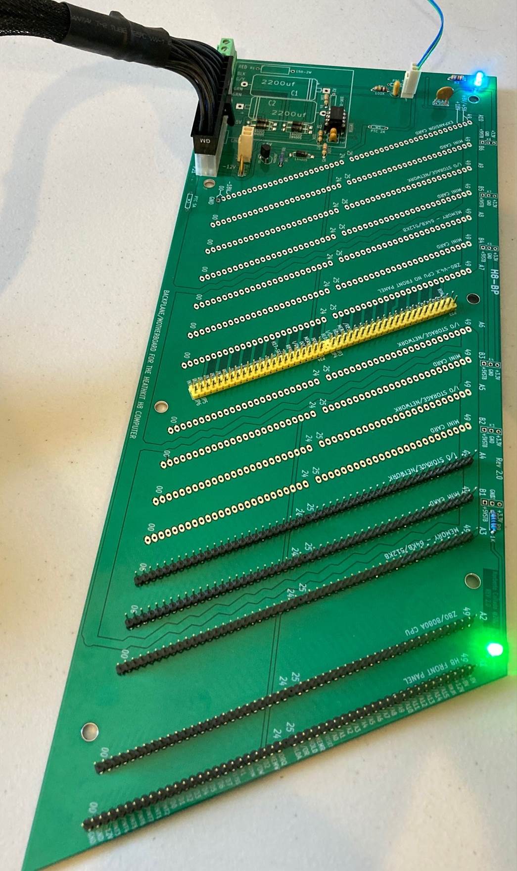
Got it working now and feel much better now that is not broken. 😊
All voltages checked out (+5V, +3.3V, +5V Standby, +12V, and -12V). Today I will test the 555 timer circuitry that controls the PSU momentary pushbutton latch.
Two minor issues.
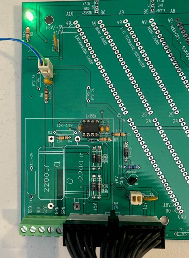
- I forgot to solder the PTC that controls the +5V power rails, so no voltage was going to the backplane. Temporary added a cable jumper to see it working.
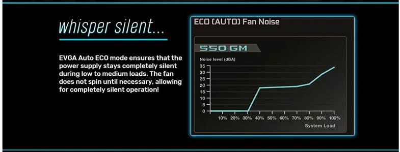
- After reviewing the PSU specs on why I thought it was shutting down, the specs mentions that the fan is off until it is necessary to turn it on to keep power supply completely silent. On power-on, the fan starts to spin-up and then it turns off. I thought the PSU was turning off due to minimum load requirements, but that was not the case. I do not think the H8 loading will ever be able to turn on the fan as it will never reach the 30% load threshold.
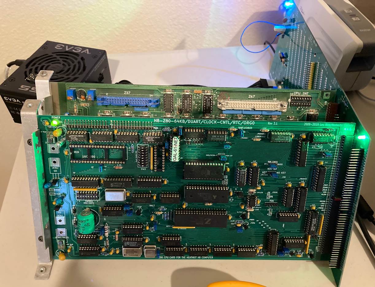
I added two 3mm LEDS to the backplane as shown on the picture. One on the front next to the Front Panel to indicate +5V is on. A second one on the back of the system indicating +5V “Standby” voltage is on. This voltage is used by the 555 timer and it could be used to keep power on RAM or RTC circuitry or other new ideas. This voltage along with the +3.3V are available at the top of the backplane to power new circuits. This allows endless ideas going forward.
New backplane up and running!
Glenn Roberts
<image001.jpg>
New backplane up and running!
<image002.jpg>
Sent from my iPhone
--
You received this message because you are subscribed to the Google Groups "SEBHC" group.
To unsubscribe from this group and stop receiving emails from it, send an email to sebhc+un...@googlegroups.com.
To view this discussion on the web visit https://groups.google.com/d/msgid/sebhc/003b01d775c1%24a55ecb70%24f01c6250%24%40koyado.com.
norberto...@koyado.com
Updates:
- PSON Switch Jumper working great.
- PSU momentary pushbutton latch circuitry working great. I did about 30 cycles and no failures detected. Very solid and stable. Even additional AC cycles to verify that the PSU does not turn on by itself when AC is applied. I love this circuit better than using PSON header.
I will add next front panel to check bus operation.
Partially assembled board pictures attached.

To view this discussion on the web visit https://groups.google.com/d/msgid/sebhc/D91E2D27-2FA5-4493-B4A2-F5FF595A8649%40gmail.com.
norberto...@koyado.com
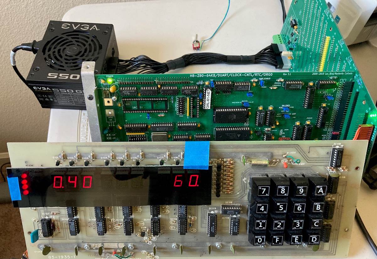
H8 Front Panel fully operational with new backplane.
Next steps:
- Complete the Backplane assembly
- Update my H8 to use this backplane and PC Power Supply.
- Do test with DUAL CPU’s.
Thanks,
Norberto
To view this discussion on the web visit https://groups.google.com/d/msgid/sebhc/006101d775dc%24b8729190%242957b4b0%24%40koyado.com.
Glenn Roberts
H8 Front Panel fully operational with new backplane.
Next steps:
- Complete the Backplane assembly
- Update my H8 to use this backplane and PC Power Supply.
- Do test with DUAL CPU’s.
<image005.jpg>
Thanks,
Norberto
From: se...@googlegroups.com <se...@googlegroups.com> On Behalf Of norberto...@koyado.com
Sent: Saturday, July 10, 2021 3:41 PM
To: se...@googlegroups.com
Subject: RE: [sebhc] Initial H8 Backplane test!
Updates:
- PSON Switch Jumper working great.
- PSU momentary pushbutton latch circuitry working great. I did about 30 cycles and no failures detected. Very solid and stable. Even additional AC cycles to verify that the PSU does not turn on by itself when AC is applied. I love this circuit better than using PSON header.
I will add next front panel to check bus operation.
Partially assembled board pictures attached.
<image001.jpg>
<image002.jpg>
To view this discussion on the web visit https://groups.google.com/d/msgid/sebhc/006a01d775e3%244533af00%24cf9b0d00%24%40koyado.com.
Steven Feinsmith
To view this discussion on the web visit https://groups.google.com/d/msgid/sebhc/006101d775dc%24b8729190%242957b4b0%24%40koyado.com.
norberto...@koyado.com
On current draw, I will need to load the whole backplane and measure it. As it has 9 main slots (not using the auxiliary slots) based on a 1Amp per slot, so it should be around 9 amps. If using my boards, I think perhaps about 5 amps. To be accurate I will need to load the backplane and measured. For now we can speculate about 10Amps or less.
The Dell PSU from Dell Optiplex 390 will work just fine as the power supply is a 265W PSU.
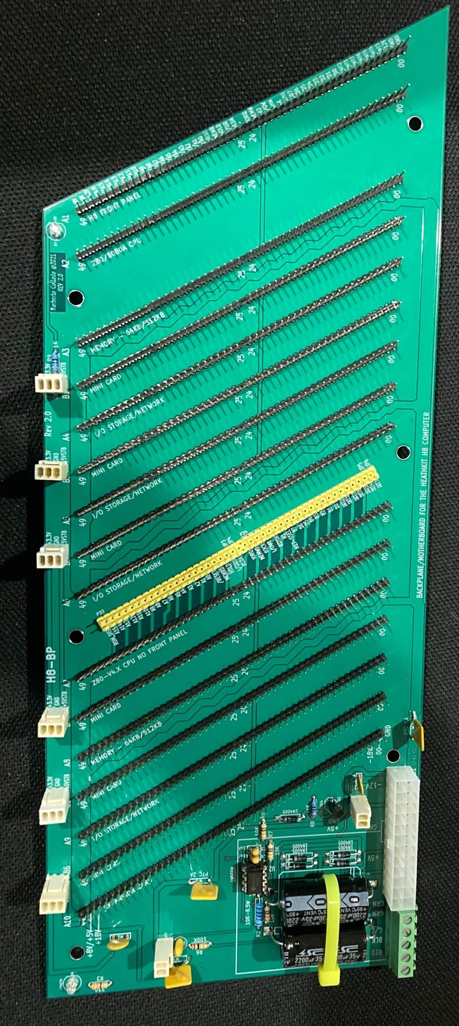
The yellow plastic header is to break the backplane into two independent backplanes. The goal is to run two Z80 systems at the same time on same chassis. You add jumpers on this header to create a single backplane or take out the jumpers and have two independent small backplanes. The first CPU will use the H8 Front Panel as always and the second CPU will run without the Front Panel as the H89 does.
One CPU could run HDOS while the second CPU could run CP/M. The first CPU will have 4 main slots for I/O devices. The second CPU will have 2 main slots. The last slot on the second CPU is labeled “Expansion Card”, so it can be expanded into another H8 backplane if needed.
Hope this helps,
Norberto
To view this discussion on the web visit https://groups.google.com/d/msgid/sebhc/CAGJMgmX8k8YOYBxBgBzjGaS6041QuL7EbAKjSwT%2BDr%3DnH0BBsg%40mail.gmail.com.
norberto.collado koyado.com

Sent: Saturday, July 10, 2021 7:28 PM
To: se...@googlegroups.com <se...@googlegroups.com>
Subject: RE: [sebhc] Initial H8 Backplane test!
pjoc...@gmail.com
The resistor is insurance that you never need to worry about what is or is not plugged into the bus.
Sent from Mail for Windows 10
To unsubscribe from this group and stop receiving emails from it, send an email to sebhc+un...@googlegroups.com.
To view this discussion on the web visit https://groups.google.com/d/msgid/sebhc/1216ece8-7017-8df8-bd6c-914d1254c904%40cfl.rr.com.
norberto.collado koyado.com
Sent: Saturday, July 10, 2021 10:51 PM
To: se...@googlegroups.com <se...@googlegroups.com>
Steven Feinsmith
To view this discussion on the web visit https://groups.google.com/d/msgid/sebhc/BN7PR01MB38448E37D2DFCBEA59F4A464F7159%40BN7PR01MB3844.prod.exchangelabs.com.
pjoc...@gmail.com
Here is a link that shows current vrs trace width Also copper weight plays in. . Forgive me if this has been discussed before as I didn’t read all the threads. Short circuit current can be calculated if you know the output impedance of the power supply. Hope this helps.
Pat
https://www.mclpcb.com/blog/pcb-trace-width-vs-current-table/
From: Steven Feinsmith
Sent: Monday, July 12, 2021 5:22 PM
To: se...@googlegroups.com
Subject: Re: [sebhc] Initial H8 Backplane test!
I am glad that you decided to make further tests to ensure the backplane will function correctly with maximum current on traces without risk of burning out. I also suggest you if you happen to have an infrared camera to see the backplane in false color. The infrared camera is blind to any visible light but can see heat. I tend to use FLIR camera attachment with my iPhone to troubleshoot the components even, heat build-up on traces. It is a straightforward method to catch the problem.
Steven
On Mon, Jul 12, 2021 at 1:47 PM norberto.collado koyado.com <norberto...@koyado.com> wrote:
Steven,
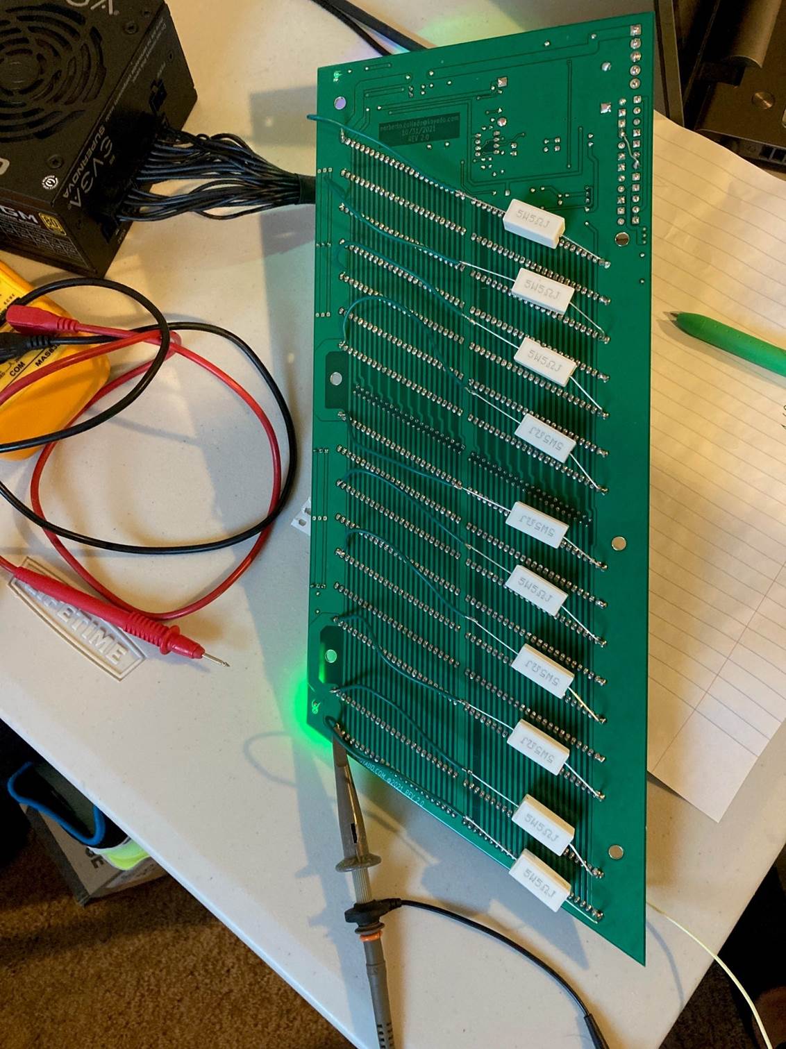
You got me thinking over the weekend on the backplane current handling capabilities. So, I decided to buy 10-pcs of 5 OHM, 5W resistors to load the backplane to 10AMP. This allows me to verify that the backplane traces can handle such current as the power traces are different than what HeathKit did.
Also, I will short out pins 48, 49 to pins 0, 1 on the backplane to verify that the backplane traces do not act as a fuse.
Thanks,
Norberto
From: se...@googlegroups.com <se...@googlegroups.com> on behalf of norberto.collado koyado.com <norberto...@koyado.com>
Sent: Saturday, July 10, 2021 10:51 PM
To: se...@googlegroups.com <se...@googlegroups.com>
Subject: Re: [sebhc] Initial H8 Backplane test!
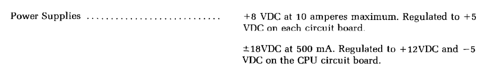
H8 Power Supply is rated at +8VDC @ 10 amps.

To view this discussion on the web visit https://groups.google.com/d/msgid/sebhc/CAGJMgmUz%2BAP3OzCajgO6uhB-HXyGJD61DZXrwWUuKooucaA%3DVA%40mail.gmail.com.
norberto.collado koyado.com
Sent: Monday, July 12, 2021 2:21 PM

Dave McGuire
I have a programmable DC load and a thermal imager in my lab; let me
know if I can assist.
-Dave
On 7/12/21 5:59 PM, norberto.collado koyado.com wrote:
> Those cameras are expensive. I think my best option will be to feel the
> heat from the trace with my fingers unless there is a better process. I
> know here at work I can take a picture and the thermal engineer will
> process the picture and send me back the thermal picture.
>
> Norberto
>
> *From:* se...@googlegroups.com <se...@googlegroups.com> on behalf of
> Steven Feinsmith <steven.f...@gmail.com>
> *Sent:* Monday, July 12, 2021 2:21 PM
> *To:* se...@googlegroups.com <se...@googlegroups.com>
> *Subject:* Re: [sebhc] Initial H8 Backplane test!
> I am glad that you decided to make further tests to ensure the backplane
> will function correctly with maximum current on traces without risk of
> burning out. I also suggest you if you happen to have an infrared camera
> to see the backplane in false color. The infrared camera is blind to any
> visible light but can see heat. I tend to use FLIR camera attachment
> with my iPhone to troubleshoot the components even, heat build-up on
> traces. It is a straightforward method to catch the problem.
>
> Steven
>
> On Mon, Jul 12, 2021 at 1:47 PM norberto.collado koyado.com
>
> Steven,
>
> You got me thinking over the weekend on the backplane current
> handling capabilities. So, I decided to buy 10-pcs of 5 OHM, 5W
> resistors to load the backplane to 10AMP. This allows me to verify
> that the backplane traces can handle such current as the power
> traces are different than what HeathKit did.
>
> Also, I will short out pins 48, 49 to pins 0, 1 on the backplane to
> verify that the backplane traces do not act as a fuse.
>
> Thanks,
> Norberto
>
> <se...@googlegroups.com <mailto:se...@googlegroups.com>> on behalf
> of norberto.collado koyado.com <http://koyado.com>
> <norberto...@koyado.com <mailto:norberto...@koyado.com>>
> *Sent:* Saturday, July 10, 2021 10:51 PM
> <se...@googlegroups.com <mailto:se...@googlegroups.com>>
> H8 Power Supply is rated at +8VDC @ 10 amps.
>
>
>
> <se...@googlegroups.com <mailto:se...@googlegroups.com>> on behalf
> of norberto...@koyado.com <mailto:norberto...@koyado.com>
> <norberto...@koyado.com <mailto:norberto...@koyado.com>>
> *Sent:* Saturday, July 10, 2021 7:28 PM
> <se...@googlegroups.com <mailto:se...@googlegroups.com>>
>
> On current draw, I will need to load the whole backplane and measure
> it. As it has 9 main slots (not using the auxiliary slots) based on
> a 1Amp per slot, so it should be around 9 amps. If using my boards,
> I think perhaps about 5 amps. To be accurate I will need to load the
> backplane and measured. For now we can speculate about 10Amps or less.
>
>
>
> The Dell PSU from Dell Optiplex 390 will work just fine as the power
> supply is a 265W PSU.
>
>
>
> The yellow plastic header is to break the backplane into two
> independent backplanes. The goal is to run two Z80 systems at the
> same time on same chassis. You add jumpers on this header to create
> a single backplane or take out the jumpers and have two independent
> small backplanes. The first CPU will use the H8 Front Panel as
> always and the second CPU will run without the Front Panel as the
> H89 does.
>
>
>
> One CPU could run HDOS while the second CPU could run CP/M. The
> first CPU will have 4 main slots for I/O devices. The second CPU
> will have 2 main slots. The last slot on the second CPU is labeled
> “Expansion Card”, so it can be expanded into another H8 backplane if
> needed.
>
>
>
> Hope this helps,
>
> Norberto
>
>
>
> <se...@googlegroups.com <mailto:se...@googlegroups.com>> *On Behalf
> *Sent:* Saturday, July 10, 2021 5:45 PM
> *Subject:* Re: [sebhc] Initial H8 Backplane test!
>
>
> Hi Norberto,
>
>
>
> It looks great, and kudos for your effort to ensure that everything
> works properly. Due to my visual problem, I could not figure out the
> middle of the backplane with yellow plastic. Can you tell me what it
> is? How much current does it draw from the PSU? Because I have an
> old Dell PSU from Dell Optiplex 390 that should be capable of
> powering the future H8 system.
>
>
>
> Steven
>
>
>
>
>
>
> On Sat, Jul 10, 2021 at 6:41 PM <norberto...@koyado.com
>
> Updates:
>
> * PSON Switch Jumper working great.
> * PSU momentary pushbutton latch circuitry working great. I
> stable. Even additional AC cycles to verify that the PSU
> does not turn on by itself when AC is applied. I love this
> circuit better than using PSON header.
>
>
>
> I will add next front panel to check bus operation.
>
>
>
> Partially assembled board pictures attached.
>
>
>
>
>
>
>
> <se...@googlegroups.com <mailto:se...@googlegroups.com>> *On
> *Sent:* Saturday, July 10, 2021 2:55 PM
> *Subject:* Re: [sebhc] Initial H8 Backplane test!
>
>
> Great! Looking good
>
> Sent from my iPad
>
>
>
> On Jul 10, 2021, at 3:27 PM, norberto...@koyado.com
>
>
>
> Got it working now and feel much better now that is not
> broken. 😊
>
>
>
> All voltages checked out (+5V, +3.3V, +5V Standby, +12V, and
> -12V). Today I will test the 555 timer circuitry that
> controls the PSU momentary pushbutton latch.
>
>
>
> Two minor issues.
>
>
>
> Temporary added a cable jumper to see it working.
> https://groups.google.com/d/msgid/sebhc/003b01d775c1%24a55ecb70%24f01c6250%24%40koyado.com
> --
> You received this message because you are subscribed to the
> Google Groups "SEBHC" group.
> To unsubscribe from this group and stop receiving emails from
> it, send an email to sebhc+un...@googlegroups.com
> <https://groups.google.com/d/msgid/sebhc/D91E2D27-2FA5-4493-B4A2-F5FF595A8649%40gmail.com?utm_medium=email&utm_source=footer>.
> --
> You received this message because you are subscribed to the
> Google Groups "SEBHC" group.
> To unsubscribe from this group and stop receiving emails from
> it, send an email to sebhc+un...@googlegroups.com
> <https://groups.google.com/d/msgid/sebhc/006101d775dc%24b8729190%242957b4b0%24%40koyado.com?utm_medium=email&utm_source=footer>.
> --
> You received this message because you are subscribed to the Google
> Groups "SEBHC" group.
> To unsubscribe from this group and stop receiving emails from it,
> send an email to sebhc+un...@googlegroups.com
> <https://groups.google.com/d/msgid/sebhc/CAGJMgmX8k8YOYBxBgBzjGaS6041QuL7EbAKjSwT%2BDr%3DnH0BBsg%40mail.gmail.com?utm_medium=email&utm_source=footer>.
> --
> You received this message because you are subscribed to the Google
> Groups "SEBHC" group.
> To unsubscribe from this group and stop receiving emails from it,
> send an email to sebhc+un...@googlegroups.com
> <https://groups.google.com/d/msgid/sebhc/000001d775fc%2475d6d1a0%24618474e0%24%40koyado.com?utm_medium=email&utm_source=footer>.
> --
> You received this message because you are subscribed to the Google
> Groups "SEBHC" group.
> To unsubscribe from this group and stop receiving emails from it,
> send an email to sebhc+un...@googlegroups.com
> <https://groups.google.com/d/msgid/sebhc/SN6PR01MB38557C183DA9DB7111D29C7EF7169%40SN6PR01MB3855.prod.exchangelabs.com?utm_medium=email&utm_source=footer>.
> --
> You received this message because you are subscribed to the Google
> Groups "SEBHC" group.
> To unsubscribe from this group and stop receiving emails from it,
> send an email to sebhc+un...@googlegroups.com
> <https://groups.google.com/d/msgid/sebhc/BN7PR01MB38448E37D2DFCBEA59F4A464F7159%40BN7PR01MB3844.prod.exchangelabs.com?utm_medium=email&utm_source=footer>.
> --
> You received this message because you are subscribed to the Google
> Groups "SEBHC" group.
> To unsubscribe from this group and stop receiving emails from it, send
> an email to sebhc+un...@googlegroups.com
> <https://groups.google.com/d/msgid/sebhc/CAGJMgmUz%2BAP3OzCajgO6uhB-HXyGJD61DZXrwWUuKooucaA%3DVA%40mail.gmail.com?utm_medium=email&utm_source=footer>.
> --
> You received this message because you are subscribed to the Google
> Groups "SEBHC" group.
> To unsubscribe from this group and stop receiving emails from it, send
> an email to sebhc+un...@googlegroups.com
> <https://groups.google.com/d/msgid/sebhc/BN7PR01MB3844FADA77F4C43D78D6D2A0F7159%40BN7PR01MB3844.prod.exchangelabs.com?utm_medium=email&utm_source=footer>.
--
Dave McGuire, AK4HZ
New Kensington, PA
Steven Feinsmith
To view this discussion on the web visit https://groups.google.com/d/msgid/sebhc/BN7PR01MB3844FADA77F4C43D78D6D2A0F7159%40BN7PR01MB3844.prod.exchangelabs.com.
norberto.collado koyado.com
- Front Panel - slot A1
- 8080A CPU - slot A2
- 64K memory - slot A3
- H17 controller - slot A4
- H8 Serial board - slot A5
- Spare - slot A6
- Z80 V4.0 - slot A7
- 512KB RAM - slot A8
- H17/H37/H67 controller - slot A9
- Expansion card - slot A10.
norberto...@koyado.com
I will install both power connectors so that you can attach a power source such as +5V that can provide more than 10 amps.
Thanks,
Norberto
To view this discussion on the web visit https://groups.google.com/d/msgid/sebhc/8fb6a038-b824-ac49-50c5-ec6e9ea01168%40neurotica.com.
norberto...@koyado.com
Steven,
I loaded the backplane with 5W/5 OHMs for a total of 10 amps or 50 watts @5Vcc. I left the backplane with this load for an 1hr. The +5Vcc traces were cold to the touch. The ground plane was warn due to heat coming from the 5W resistors. The 5 amps PTC fuses did get hot, but did not trigger. The backplane worked fine under these extreme load conditions. As the ATX PSU can drive 30Amp on the +5Vcc traces, I’m limiting it to 10 amps with the PTC fuse to protect the backplane. Also the +12v can drive 46 amps, it is limited to 1 amp as well as the -12V. As I have two 5 amps paths to the +5V load, I forgot to add a trace to combined them, so I had to solder a piece of wire as shown on the picture below. I fixed that for the production board. I feel happy that flowing 10amps thru the board for an hr. did not damaged any copper traces.
During the testing I also noticed that I need to add two 2-pin header to provide +12V/GND and +5V/GND to drive a +12V or +5V fan for the system if needed.
PTC Fuse specs:
Holding Current:5A
Tripping Current:8.5A
Operating Voltage: 16V
TEMP MEASUREMENTS: Using the home touchless thermometer.
PTC FUSE: 102.6F
+5V TRACE AT P9 – 93 F
+5V TRACE AT FRONT PANEL CONNECTOR: 96.9F
GROUND TRACE: 104.8F
Voltage across all resistors was 5Vcc, so no significant voltage drop observed.
Here is the setup:
Thanks,
Norberto
To view this discussion on the web visit https://groups.google.com/d/msgid/sebhc/SN6PR01MB38559364F69A4B892E24D274F7149%40SN6PR01MB3855.prod.exchangelabs.com.
norberto...@koyado.com
Fully assembled and tested H8 backplane. I will defer installation into the H8 chassis until 7/24 as I’m very busy until them.
To view this discussion on the web visit https://groups.google.com/d/msgid/sebhc/000001d77aca%2461f33430%2425d99c90%24%40koyado.com.