PAL-1 optimization thought
140 views
Skip to first unread message

GN L
Jan 30, 2022, 7:49:14 AM1/30/22
to PAL 6502 computer
Greetings communities,
I made the PAL-1 kit because the legendary KIM-1 and the plenty of archived information from the internet, especially Hans' site, and of course I love the 6502's history and vintage computers. Luckily, this little kit can appeal to the 8 bit enthusiasts just like you all around the world!
Thanks to all active users, I have received a lot of feedback of the PAL-1 kit from very early days, so I decided to start a new project to optimize the PAL-1 kit, a relative big upgrade to the current PAL-1 kit, all new design which will provide you a better experience and usability KIM-1 clone system.
The optimize list is,
Full KIM-1 expansion ports support, both the Application connector and Expansion connector.
A Cherry MX switch (onboard) keypad.
A dedicate keypad expansion pinhead for some programs, like the piano keyboard.
I/O selector (keypad or RS232) changes from jumper to switch.
The RS232 pinout exchange TX, RX lines, to avoid use a gender changer.
A power switch.
Compatible with current motherboard expansions.
and a new PCB color?
The list may not included all the feedbacks of PAL-1 kit, if I forgot something or you have any good idea, please discuss it here!
Thank you all,
Liu Ganning

Jeremy Starcher
Jan 30, 2022, 8:41:46 AM1/30/22
to PAL 6502 computer
Couple of thoughts as you are redesigning...
- Edge connectors? or pin header like now? Or both?
- Room for for ZIF sockets for the rom and maybe the 6502. (There are some 6502 replacements I'd love to play with)
- Pin sockets rather then blade sockets
- 5v pin headers for USB power. (I tack soldered on to the 5v rail directly.)
And while not directly related, a 'digital cassette desk' expansion would be wonderful.
GN L
Jan 30, 2022, 8:57:53 AM1/30/22
to Jeremy Starcher, PAL 6502 computer
> • Edge connectors? or pin header like now? Or both?
Pin header like now
> • Room for for ZIF sockets for the rom and maybe the 6502. (There are some 6502 replacements I'd love to play with)
Good idea!
> • Pin sockets rather then blade sockets
Yes
> • 5v pin headers for USB power. (I tack soldered on to the 5v rail directly.)
Micro USB or type-C?
About more expansions, I have put it in my bookmarks. Thanks for the information!
> On Jan 30, 2022, at 9:41 PM, Jeremy Starcher <jeremy....@gmail.com> wrote:
>
> Couple of thoughts as you are redesigning...
>
> • Edge connectors? or pin header like now? Or both?
> • Room for for ZIF sockets for the rom and maybe the 6502. (There are some 6502 replacements I'd love to play with)
> • Pin sockets rather then blade sockets
> • 5v pin headers for USB power. (I tack soldered on to the 5v rail directly.)
>
> And while not directly related, a 'digital cassette desk' expansion would be wonderful.
>
> https://github.com/mrWheel/KIM_TapeDevice
> https://willem.aandewiel.nl/index.php/2021/02/20/digital-tape-recorder-for-the-kim-1-and-clones/
>
>
>
Best,
Liu
Pin header like now
> • Room for for ZIF sockets for the rom and maybe the 6502. (There are some 6502 replacements I'd love to play with)
Good idea!
> • Pin sockets rather then blade sockets
Yes
> • 5v pin headers for USB power. (I tack soldered on to the 5v rail directly.)
Micro USB or type-C?
About more expansions, I have put it in my bookmarks. Thanks for the information!
> On Jan 30, 2022, at 9:41 PM, Jeremy Starcher <jeremy....@gmail.com> wrote:
>
> Couple of thoughts as you are redesigning...
>
> • Edge connectors? or pin header like now? Or both?
> • Room for for ZIF sockets for the rom and maybe the 6502. (There are some 6502 replacements I'd love to play with)
> • Pin sockets rather then blade sockets
> • 5v pin headers for USB power. (I tack soldered on to the 5v rail directly.)
>
> And while not directly related, a 'digital cassette desk' expansion would be wonderful.
>
> https://github.com/mrWheel/KIM_TapeDevice
> https://willem.aandewiel.nl/index.php/2021/02/20/digital-tape-recorder-for-the-kim-1-and-clones/
>
>
>
Liu

Neil Andretti
Jan 30, 2022, 9:11:19 AM1/30/22
to PAL 6502 computer
> • 5v pin headers for USB power. (I tack soldered on to the 5v rail directly.)
Micro USB or type-C?
micro USB, as type-C needs an intelligent current regulation iirc.
> And while not directly related, a 'digital cassette desk' expansion would be wonderful.
>
> https://github.com/mrWheel/KIM_TapeDevice
> https://willem.aandewiel.nl/index.php/2021/02/20/digital-tape-recorder-for-the-kim-1-and-clones/
the Willems dtr fits directly into the motherboard.
GN L
Jan 30, 2022, 9:31:13 AM1/30/22
to Neil Andretti, PAL 6502 computer
> micro USB, as type-C needs an intelligent current regulation iirc.
Got you, Micro USB.
And for those interested in Willems tape recorder, nils has some videos at https://www.youtube.com/user/masterhit1
>
> --
> You received this message because you are subscribed to the Google Groups "PAL 6502 computer" group.
> To unsubscribe from this group and stop receiving emails from it, send an email to pal6502+u...@googlegroups.com.
> To view this discussion on the web visit https://groups.google.com/d/msgid/pal6502/74fe4ee1-c642-40ee-b490-4612ca1dad5en%40googlegroups.com.
> For more options, visit https://groups.google.com/d/optout.
> <dr.jpg>
Best,
Liu

Jim McClanahan
Jan 30, 2022, 4:49:20 PM1/30/22
to GN L, pal...@googlegroups.com
One thing that would help troubleshoot potential serial port issues (for new builds) would be LEDs on the TX and RX lines. I would tend to use small LEDs and oversize the current limiting resistors so they weren't particularly bright.
With that and a simple program you could test the serial port and have a clear visual indication of what was going on.
It would also be nice to be able to bank switch the onboard EPROM with a jumper and have the clock oscillator socketed (I should have done that when I built mine) if you decide to overclock things a bit.
Thanks,
Jim W4JBM
--
You received this message because you are subscribed to the Google Groups "PAL 6502 computer" group.
To unsubscribe from this group and stop receiving emails from it, send an email to pal6502+u...@googlegroups.com.
To view this discussion on the web visit https://groups.google.com/d/msgid/pal6502/6C45B4A5-D4DD-46F6-B2B0-3FD9221EA61D%40gmail.com.
GN L
Jan 30, 2022, 9:52:02 PM1/30/22
to Jim McClanahan, pal...@googlegroups.com
Thanks Jim.
> On Jan 31, 2022, at 5:48 AM, Jim McClanahan <jim3...@gmail.com> wrote:
>
> One thing that would help troubleshoot potential serial port issues (for new builds) would be LEDs on the TX and RX lines. I would tend to use small LEDs and oversize the current limiting resistors so they weren't particularly bright.
>
> With that and a simple program you could test the serial port and have a clear visual indication of what was going on.
Do you prefer these two LED through hole components or SMD?
>
> It would also be nice to be able to bank switch the onboard EPROM with a jumper and have the clock oscillator socketed (I should have done that when I built mine) if you decide to overclock things a bit.
I don’t understand what the bank switch for the onboard EPROM use for? You mean to select another bank(s) of the onboard EPROM instead of the default KIM-1 monitor bank, so we can load another monitor, even OS from the currently unused space on the onboard EPROM?
What oscillator socket do you prefer, square or rectangle?
>
> Thanks,
> Jim W4JBM
>
Best,
Liu
> On Jan 31, 2022, at 5:48 AM, Jim McClanahan <jim3...@gmail.com> wrote:
>
> One thing that would help troubleshoot potential serial port issues (for new builds) would be LEDs on the TX and RX lines. I would tend to use small LEDs and oversize the current limiting resistors so they weren't particularly bright.
>
> With that and a simple program you could test the serial port and have a clear visual indication of what was going on.
>
> It would also be nice to be able to bank switch the onboard EPROM with a jumper and have the clock oscillator socketed (I should have done that when I built mine) if you decide to overclock things a bit.
What oscillator socket do you prefer, square or rectangle?
>
> Thanks,
> Jim W4JBM
>
Best,
Liu

Hans Otten
Jan 31, 2022, 4:24:10 AM1/31/22
to PAL 6502 computer
What makes a KIM-1 a KIM-1 and what a clone must minimally have
- 6502 CPU at 1 MHz
- 2x 6530 RRIOT, one devoted to KIM-1 ROM usage, one free for user)
- 1K RAM $0000 up
- 1K ROM with KIM (bit banging serial, scanning and LED and keyboard in loop, monitor program, single step
- 1K ROM with Tape read/write (this needs timer in RRIOT)
- 6 seven segments LED
- 23 key keypad, matrix
- TTY interface and audio cassette interface with logic ports controlling it
- Memory map with I/O in $17XX , RRIOT RAM in $17XX, so other RAM has gap between $1400/$1600 and $2000
- Single step circuit using NMI
- Default unexpanded memory map, so the 16 pages overlap (K0-K7 decoding to $K pages) or are fully extended with external hardware.
- Fully extended needs care of RESET/NMI/IRQ vector locations
- Expansion connector (mostly CPU and decode signals)
- Application connector (mostly the second RRIOT).
I have looked at what I have as KIM clones (the PAL-1, the MicroKIM, The Corsham KIM CLone Rev 3 and 5) and the MOS KIM Reproduction to come up with suggestions for a PAL-2.
The PAL-1 and MicroKIM are nearly identical and excellent designs. The first real usable version of KIM cloning based upon the work by Ruud Baltissen.
The Corsham KIM Clone is a bit different and less KIM-1 compatible (missing logic for tape, the ROM has changed), but well usable and designed with expansion via motherboard and cards like prototyping, VIA/ACIA, mass storage on SD.
The MOS KIM Reproduction by Dave Williams is a real complete KIM-1! You have to look twice to see a difference and looks beautiful too.
The only innovation is the use of the 6532 in stead of the 6530.
Suggestions on PAL-2
Motto: make it a real and complete KIM-1 in functionality!
- keep the logic as is, it is now as close tot he original KIM-1 as is possible, so do not leave out anything
- keep the KIM ROM original, any changes may break programs
- keypad needs better keys (labels on top)
- use a switch for TTY/Keypad selection
- integrate the second 6532 on board (which will lead to an expansion connector)
- optional the audio circuit could be onboard, though the external board is perhaps good enough
- replace the 8K RAM with a large SRAM like 628128, and have the PAL-1 have fully RAM extended on board
- Leave the Expansion port as is, so we can use the current motherboard and cards
- Add an application connector (also 40 pin) with all missing signals from the KIM-1 application and expansion connector
- Add jumper to allow the WDC65C02 CPU (BE signal)
- make the PCB pads for the transistors big, it is the most difficult part of putting the kit together
- make the TTY interface TTL compatible, so attaching USB serial is easy. Leave out the RS232 part (which the KIM-1 also does not have!)
- optional have LEDS on the RX/TX lines
- enough jumpers to choose memory layout (fully expanded etc)
- use EEPROM for the KIM-1 ROM
- option ROM 8K (not EPROM but EEPROM) at high memory
- use USB-C connector for power, a mechanically stable and reliable and future proof
- optional board to connect PAL-1 connectors to KIM-1 type edge connectors, rerouting all signals. I doubt it will be used a lot, but it makes it a real KIM-1!
The current motherboard and cards will remain usable as the expansion connector is identical.
A new motherboard connected to application and expansion port:
- Double row of connectors.
- Accepts the current boards, so it is upwards compatible.
Suggestions for new cards:
- an option board for prototyping on application and expansion
- an option board with 68B50 serial ACIA and 2x VIA 6522
Neil Andretti
Jan 31, 2022, 6:05:34 AM1/31/22
to PAL 6502 computer
Just read a bit about USB-C https://en.wikipedia.org/wiki/USB-C ... what a horrible mess....
But:
VBUS and GND provide 5 V up to 900 mA, in accordance with the USB 3.1 specification.
USB Power Delivery uses one of CC1, CC2 pins for power negotiation between source and sink up to 20 V at 5 A.
So this can be used as long as CC1 and CC2 are not touched, if I understad this right.
hansj...@gmail.com schrieb am Montag, 31. Januar 2022 um 10:24:10 UTC+1:
- integrate the second 6532 on board (which will lead to an expansion connector)
- optional the audio circuit could be onboard, though the external board is perhaps good enough
- replace the 8K RAM with a large SRAM like 628128, and have the PAL-1 have fully RAM extended on board
- Leave the Expansion port as is, so we can use the current motherboard and cards
- Add an application connector (also 40 pin) with all missing signals from the KIM-1 application and expansion connector
- Add jumper to allow the WDC65C02 CPU (BE signal)
- make the PCB pads for the transistors big, it is the most difficult part of putting the kit together
- make the TTY interface TTL compatible, so attaching USB serial is easy. Leave out the RS232 part (which the KIM-1 also does not have!)
- optional have LEDS on the RX/TX lines
- enough jumpers to choose memory layout (fully expanded etc)
- use EEPROM for the KIM-1 ROM
- option ROM 8K (not EPROM but EEPROM) at high memory
- use USB-C connector for power, a mechanically stable and reliable and future proof
This sums it up fairly well. I've seen the USB power / TTL hack by arduining and indeed this would solve all the connection problems that occured with non working usb - serial adapters (and save some parts).
Also a lot of the expansion boards would be integrated, which is a good thing.
nils
Hans Otten
Jan 31, 2022, 7:23:29 AM1/31/22
to PAL 6502 computer
Indeed USB-C requires at least 2 pullups to CC1, CC2.
Mini USB is easier.
I forgot power on/off switch in my suggestion list.

Hendrik-Jan Megens
Jan 31, 2022, 7:50:04 AM1/31/22
to Liu GN, PAL 6502 computer
My personal 2 cents - keep it simple.
The one thing that attracted me to the PAL-1 was that it was cheap and 'small enough' as a project to even think about assembling it myself, having not too much experience with putting together complex kits like this. (So PLEASE only through hole components!! )
I'm sure you can fit tons of things - I actually appreciated having the DB9 connector (I hope you keep it, or otherwise create an expansion board) since that made it so much easier to start working with it. Again, being a bit of a Noob and all.
I like the modular design - having that second RIOT as an optional expansion is clever and keeps the main board small enough to fit in a small project box. I also like the RAM and ROM expansion modules - not only because they give more capabilities, but especially because they limit the PAL-1 to be something more similar to the original. For me a large part of the fun is having something that is SO close to the original feel (I think - I don't own a real KIM-1). And simple enough to understand what's going on. Having tons of RAM or a second ROM on board would 'degrade' the PAL-1 to the KIM-UNO. Which is fantastic little device, for sure, but doesn't give me the same vintage vibes. More experienced users will probably find these arguments silly, but, again, just my 2c.
Literally the only improvement I can think of that I would value is the keypad - and even there you have to be careful imho not to overdo it. But, for improved usability having cherry switches and legends on keycaps really helps.
And happy Chinese Newyear!
Hendrik-Jan
--
You received this message because you are subscribed to the Google Groups "PAL 6502 computer" group.
To unsubscribe from this group and stop receiving emails from it, send an email to pal6502+u...@googlegroups.com.
To view this discussion on the web visit https://groups.google.com/d/msgid/pal6502/fae2da45-49b9-428f-b67c-4a5113201226n%40googlegroups.com.
GN L
Jan 31, 2022, 8:10:53 AM1/31/22
to Hans Otten, PAL 6502 computer
Thanks Hans, I will read word for word!
Best,
Liu
Liu
GN L
Jan 31, 2022, 8:17:10 AM1/31/22
to Neil Andretti, PAL 6502 computer
Thanks nils,
>
> hansj...@gmail.com schrieb am Montag, 31. Januar 2022 um 10:24:10 UTC+1:
>
> - integrate the second 6532 on board (which will lead to an expansion connector)
> - optional the audio circuit could be onboard, though the external board is perhaps good enough
> - replace the 8K RAM with a large SRAM like 628128, and have the PAL-1 have fully RAM extended on board
> - Leave the Expansion port as is, so we can use the current motherboard and cards
> - Add an application connector (also 40 pin) with all missing signals from the KIM-1 application and expansion connector
> - Add jumper to allow the WDC65C02 CPU (BE signal)
> - make the PCB pads for the transistors big, it is the most difficult part of putting the kit together
> - make the TTY interface TTL compatible, so attaching USB serial is easy. Leave out the RS232 part (which the KIM-1 also does not have!)
> - optional have LEDS on the RX/TX lines
> - enough jumpers to choose memory layout (fully expanded etc)
> - use EEPROM for the KIM-1 ROM
> - option ROM 8K (not EPROM but EEPROM) at high memory
> - use USB-C connector for power, a mechanically stable and reliable and future proof
>
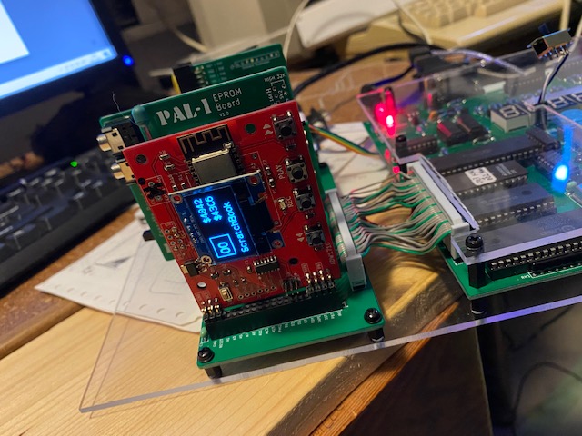
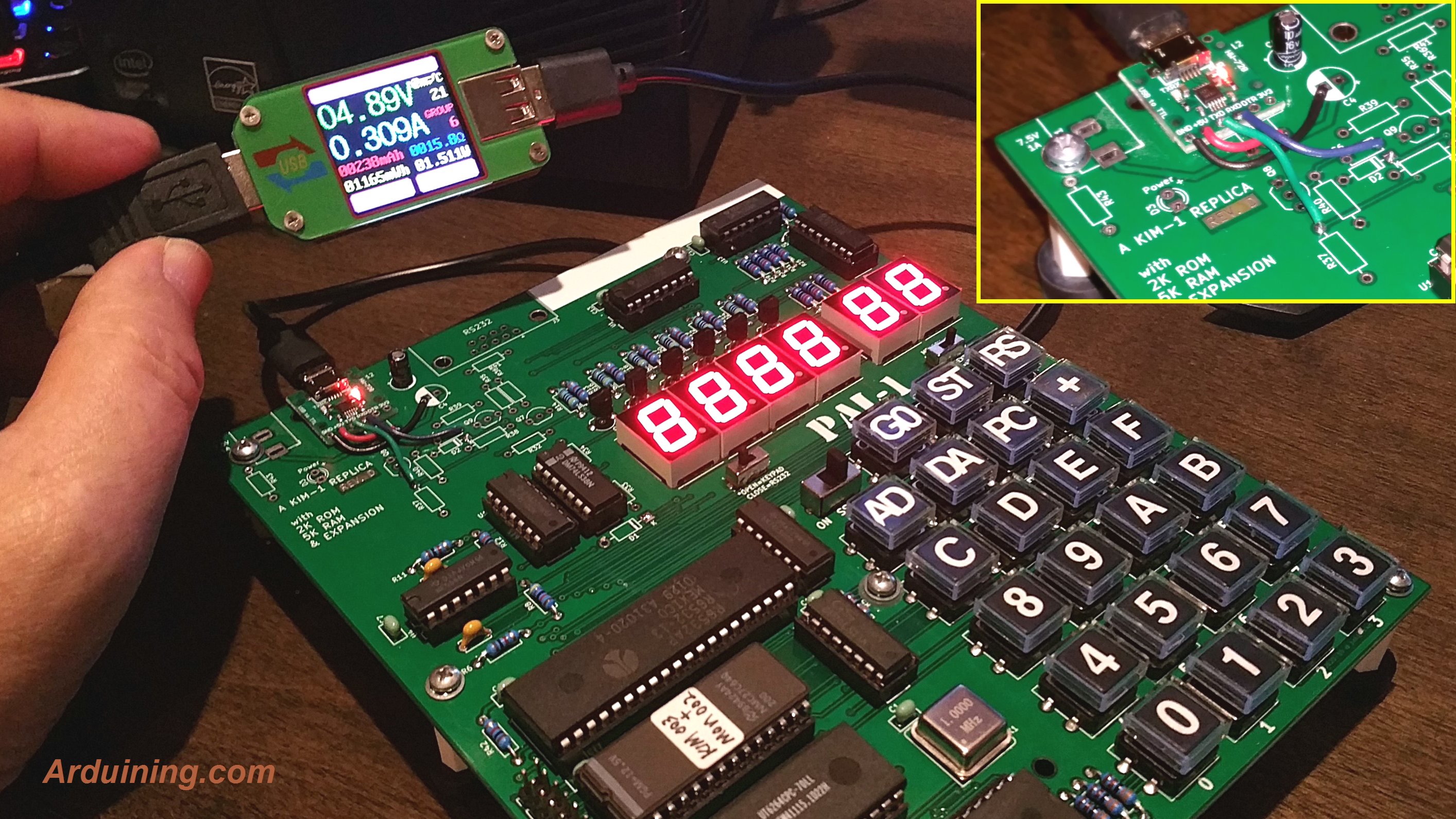
> This sums it up fairly well. I've seen the USB power / TTL hack by arduining and indeed this would solve all the connection problems that occured with non working usb - serial adapters (and save some parts).
> Also a lot of the expansion boards would be integrated, which is a good thing.
>
> <powerhack.jpg>
Arduining made a very impressive mod on PAL-1, I’ll try to integrate the TTL part in the new version.
>
> nils
Best,
Liu
> On Jan 31, 2022, at 7:05 PM, 'Neil Andretti' via PAL 6502 computer <pal...@googlegroups.com> wrote:
>
> Just read a bit about USB-C https://en.wikipedia.org/wiki/USB-C ... what a horrible mess....
> But: VBUS and GND provide 5 V up to 900 mA, in accordance with the USB 3.1 specification. USB Power Delivery uses one of CC1, CC2 pins for power negotiation between source and sink up to 20 V at 5 A.
> So this can be used as long as CC1 and CC2 are not touched, if I understad this right.
>
I’ll try my best to adapt a USB-C to power new version PAL.
>
> Just read a bit about USB-C https://en.wikipedia.org/wiki/USB-C ... what a horrible mess....
> But: VBUS and GND provide 5 V up to 900 mA, in accordance with the USB 3.1 specification. USB Power Delivery uses one of CC1, CC2 pins for power negotiation between source and sink up to 20 V at 5 A.
> So this can be used as long as CC1 and CC2 are not touched, if I understad this right.
>
>
> hansj...@gmail.com schrieb am Montag, 31. Januar 2022 um 10:24:10 UTC+1:
>
> - integrate the second 6532 on board (which will lead to an expansion connector)
> - optional the audio circuit could be onboard, though the external board is perhaps good enough
> - replace the 8K RAM with a large SRAM like 628128, and have the PAL-1 have fully RAM extended on board
> - Leave the Expansion port as is, so we can use the current motherboard and cards
> - Add an application connector (also 40 pin) with all missing signals from the KIM-1 application and expansion connector
> - Add jumper to allow the WDC65C02 CPU (BE signal)
> - make the PCB pads for the transistors big, it is the most difficult part of putting the kit together
> - make the TTY interface TTL compatible, so attaching USB serial is easy. Leave out the RS232 part (which the KIM-1 also does not have!)
> - optional have LEDS on the RX/TX lines
> - enough jumpers to choose memory layout (fully expanded etc)
> - use EEPROM for the KIM-1 ROM
> - option ROM 8K (not EPROM but EEPROM) at high memory
> - use USB-C connector for power, a mechanically stable and reliable and future proof
>
> This sums it up fairly well. I've seen the USB power / TTL hack by arduining and indeed this would solve all the connection problems that occured with non working usb - serial adapters (and save some parts).
> Also a lot of the expansion boards would be integrated, which is a good thing.
>
Arduining made a very impressive mod on PAL-1, I’ll try to integrate the TTL part in the new version.
>
> nils
Best,
Liu
GN L
Jan 31, 2022, 8:18:34 AM1/31/22
to Hans Otten, PAL 6502 computer
> On Jan 31, 2022, at 8:23 PM, Hans Otten <hansj...@gmail.com> wrote:
>
> Indeed USB-C requires at least 2 pullups to CC1, CC2.
> Mini USB is easier.
>
> I forgot power on/off switch in my suggestion list.
Best,
Liu
GN L
Jan 31, 2022, 8:26:51 AM1/31/22
to Hendrik-Jan Megens, PAL 6502 computer
Thanks Hendrik-Jan,
> On Jan 31, 2022, at 8:49 PM, Hendrik-Jan Megens <hjme...@gmail.com> wrote:
>
> My personal 2 cents - keep it simple.
K.I.S.S.
>
> The one thing that attracted me to the PAL-1 was that it was cheap and 'small enough' as a project to even think about assembling it myself, having not too much experience with putting together complex kits like this. (So PLEASE only through hole components!! )
Set the design target: only through hole components.
>
> I'm sure you can fit tons of things - I actually appreciated having the DB9 connector (I hope you keep it, or otherwise create an expansion board) since that made it so much easier to start working with it. Again, being a bit of a Noob and all.
>
> I like the modular design - having that second RIOT as an optional expansion is clever and keeps the main board small enough to fit in a small project box. I also like the RAM and ROM expansion modules - not only because they give more capabilities, but especially because they limit the PAL-1 to be something more similar to the original. For me a large part of the fun is having something that is SO close to the original feel (I think - I don't own a real KIM-1). And simple enough to understand what's going on. Having tons of RAM or a second ROM on board would 'degrade' the PAL-1 to the KIM-UNO. Which is fantastic little device, for sure, but doesn't give me the same vintage vibes. More experienced users will probably find these arguments silly, but, again, just my 2c.
I think I know how you feel, I’ll keep the feeling in the revision PAL.
>
> Literally the only improvement I can think of that I would value is the keypad - and even there you have to be careful imho not to overdo it. But, for improved usability having cherry switches and legends on keycaps really helps.
The keypad seems a must upgrade part~
>
> And happy Chinese Newyear!
壬寅年快乐!(Happy tiger year)
>
> Hendrik-Jan
Best,
Liu
> On Jan 31, 2022, at 8:49 PM, Hendrik-Jan Megens <hjme...@gmail.com> wrote:
>
> My personal 2 cents - keep it simple.
>
> The one thing that attracted me to the PAL-1 was that it was cheap and 'small enough' as a project to even think about assembling it myself, having not too much experience with putting together complex kits like this. (So PLEASE only through hole components!! )
>
> I'm sure you can fit tons of things - I actually appreciated having the DB9 connector (I hope you keep it, or otherwise create an expansion board) since that made it so much easier to start working with it. Again, being a bit of a Noob and all.
>
> I like the modular design - having that second RIOT as an optional expansion is clever and keeps the main board small enough to fit in a small project box. I also like the RAM and ROM expansion modules - not only because they give more capabilities, but especially because they limit the PAL-1 to be something more similar to the original. For me a large part of the fun is having something that is SO close to the original feel (I think - I don't own a real KIM-1). And simple enough to understand what's going on. Having tons of RAM or a second ROM on board would 'degrade' the PAL-1 to the KIM-UNO. Which is fantastic little device, for sure, but doesn't give me the same vintage vibes. More experienced users will probably find these arguments silly, but, again, just my 2c.
>
> Literally the only improvement I can think of that I would value is the keypad - and even there you have to be careful imho not to overdo it. But, for improved usability having cherry switches and legends on keycaps really helps.
>
> And happy Chinese Newyear!
壬寅年快乐!(Happy tiger year)
>
> Hendrik-Jan
Best,
Liu
Hans Otten
Jan 31, 2022, 1:42:34 PM1/31/22
to PAL 6502 computer
Hendrik-Jan has valid points: keep it simple and trough hole only.
As a wise man once said: “Make everything as simple as possible, but not simpler.” Albert Einstein
My suggestions also lead to a simple but not too simple design and deliver a real complete KIM-1
- removal of RS232 is a simplification, reduces components and saves quite some board space
- bigger RAM IC means no external RAM card required (saving) and hardly makes board more complex (still one IC)
- audio may stay as extra card, not everybody will use that (though it is part of a KIM-1)
- extra option ROM card is just as useful and not really standard KIM-1, so let that be external
Extra 6532 is such an integral part of the KIM-1 and required for a useful, also an essential KIM-1 feature, application connector.
And keys need labels, but do not have to be big size! Keep it small ;)
Hans
GN L
Feb 1, 2022, 12:22:11 AM2/1/22
to Hans Otten, PAL 6502 computer
> On Feb 1, 2022, at 2:42 AM, Hans Otten <hansj...@gmail.com> wrote:
>
> Hendrik-Jan has valid points: keep it simple and trough hole only.
>
> As a wise man once said: “Make everything as simple as possible, but not simpler.” Albert Einstein
>
> My suggestions also lead to a simple but not too simple design and deliver a real complete KIM-1
> - removal of RS232 is a simplification, reduces components and saves quite some board space
> - bigger RAM IC means no external RAM card required (saving) and hardly makes board more complex (still one IC)
> - audio may stay as extra card, not everybody will use that (though it is part of a KIM-1)
> - extra option ROM card is just as useful and not really standard KIM-1, so let that be external
>
> Extra 6532 is such an integral part of the KIM-1 and required for a useful, also an essential KIM-1 feature, application connector.
>
> And keys need labels, but do not have to be big size! Keep it small ;)
>
> Hans
Best,
Liu

John Kennedy
Feb 1, 2022, 6:22:12 AM2/1/22
to PAL 6502 computer
I would get the new kit for the keypad alone :-)
I have some other ideas, which may stray too far from the original but anyway:
* Battery backed or flash RAM in place of standard RAM, so that my code isn't lost between sessions (or my NMI vectors!)
* Built-in electronics to support a serial terminal i.e. video out and keyboard in.
* A system that can copy the entire contents of RAM to and from an SD card.
* On-board battery and charger to make it into a laptop :-)
Hendrik-Jan Megens
Feb 1, 2022, 6:50:07 AM2/1/22
to PAL 6502 computer
Hi Liu,
note there are cherry-compatible switches with low height/travel. Cherry makes them but for an inexpensive option there are plenty quality clones out there. The footprint is the same I think as the original, full height cherry's but actually I don't think that is that much more than the switches you are using now.
Cheers,
Hendrik-Jan
GN L
Feb 4, 2022, 12:37:36 AM2/4/22
to John Kennedy, PAL 6502 computer
Hi John,
I’ll try my best, your vision is lightyear ahead of mine ;)
> On Feb 1, 2022, at 7:22 PM, John Kennedy <johntk...@gmail.com> wrote:
>
> I would get the new kit for the keypad alone :-)
>
> I have some other ideas, which may stray too far from the original but anyway:
>
> * Battery backed or flash RAM in place of standard RAM, so that my code isn't lost between sessions (or my NMI vectors!)
> * Built-in electronics to support a serial terminal i.e. video out and keyboard in.
> * A system that can copy the entire contents of RAM to and from an SD card.
> * On-board battery and charger to make it into a laptop :-)
Best,
Liu
I’ll try my best, your vision is lightyear ahead of mine ;)
> On Feb 1, 2022, at 7:22 PM, John Kennedy <johntk...@gmail.com> wrote:
>
> I would get the new kit for the keypad alone :-)
>
> I have some other ideas, which may stray too far from the original but anyway:
>
> * Battery backed or flash RAM in place of standard RAM, so that my code isn't lost between sessions (or my NMI vectors!)
> * Built-in electronics to support a serial terminal i.e. video out and keyboard in.
> * A system that can copy the entire contents of RAM to and from an SD card.
> * On-board battery and charger to make it into a laptop :-)
Liu
GN L
Feb 4, 2022, 12:40:23 AM2/4/22
to Hendrik-Jan Megens, PAL 6502 computer
Hi Hendrik-Jan,
Thanks for the information, I find some brand of these low profile switches, I’ll buy some to see if they fit the project.
> On Feb 1, 2022, at 7:50 PM, Hendrik-Jan Megens <hjme...@gmail.com> wrote:
>
> Hi Liu,
>
> note there are cherry-compatible switches with low height/travel. Cherry makes them but for an inexpensive option there are plenty quality clones out there. The footprint is the same I think as the original, full height cherry's but actually I don't think that is that much more than the switches you are using now.
>
> Cheers,
> Hendrik-Jan
Best,
Liu
Thanks for the information, I find some brand of these low profile switches, I’ll buy some to see if they fit the project.
> On Feb 1, 2022, at 7:50 PM, Hendrik-Jan Megens <hjme...@gmail.com> wrote:
>
> Hi Liu,
>
> note there are cherry-compatible switches with low height/travel. Cherry makes them but for an inexpensive option there are plenty quality clones out there. The footprint is the same I think as the original, full height cherry's but actually I don't think that is that much more than the switches you are using now.
>
> Cheers,
> Hendrik-Jan
Liu
Hans Otten
Feb 23, 2022, 3:51:34 AM2/23/22
to PAL 6502 computer
Liu, how is the redesign going? Already have decided what to add/change?
GN L
Feb 23, 2022, 4:58:22 AM2/23/22
to Hans Otten, PAL 6502 computer
Hi Hans,
I’m still working on it. Like the mail you wrote before, the goal is a full and real KIM-1, with some modern compatible designs, such as 65c02 support.
I’m now based on the circuit on your site (http://retro.hansotten.nl/wp-content/uploads/2015/05/kim-new-1.png), with very little modification like the BE(pin 36), MLB(pin 5), VPB(pin 1) and SYNC mod when using a 65c02. But I still not fully understand/test these pin requirements to get the c02 to work on the KIM-1.
The new design will has two 6532s on base board, but leave the audio part for expansion. And I’ll try to use ttl for the tty interface on base board and a RS232 add-on card for more retro people.
For the ROM, I want to find a 2K EEPROM to accurate fit the KIM ROM.
And a large RAM chip can cover 64KB extension with memory layout jumpers but default to 1K as KIM-1 (all switches off). The memory layout will compatible with Jim’s ROM board for PAL-1.
> On Feb 23, 2022, at 4:51 PM, Hans Otten <hansj...@gmail.com> wrote:
>
> Liu, how is the redesign going? Already have decided what to add/change?
>
Best,
Liu
I’m still working on it. Like the mail you wrote before, the goal is a full and real KIM-1, with some modern compatible designs, such as 65c02 support.
I’m now based on the circuit on your site (http://retro.hansotten.nl/wp-content/uploads/2015/05/kim-new-1.png), with very little modification like the BE(pin 36), MLB(pin 5), VPB(pin 1) and SYNC mod when using a 65c02. But I still not fully understand/test these pin requirements to get the c02 to work on the KIM-1.
The new design will has two 6532s on base board, but leave the audio part for expansion. And I’ll try to use ttl for the tty interface on base board and a RS232 add-on card for more retro people.
For the ROM, I want to find a 2K EEPROM to accurate fit the KIM ROM.
And a large RAM chip can cover 64KB extension with memory layout jumpers but default to 1K as KIM-1 (all switches off). The memory layout will compatible with Jim’s ROM board for PAL-1.
> On Feb 23, 2022, at 4:51 PM, Hans Otten <hansj...@gmail.com> wrote:
>
> Liu, how is the redesign going? Already have decided what to add/change?
>
Liu
Hans Otten
Feb 23, 2022, 6:56:45 AM2/23/22
to PAL 6502 computer
Also have a look at the Corsham KIM clone circuit. Bob went from V1 to V5 after some suggestions by the community to add the expansion connectors. He did leave out the logic for the audio circuit, which I think is a pity. I am not sure the 2015 circuit is without errors, better double check with your current working design.
GN L
Feb 23, 2022, 7:21:09 AM2/23/22
to Hans Otten, PAL 6502 computer
Got it!
> On Feb 23, 2022, at 7:56 PM, Hans Otten <hansj...@gmail.com> wrote:
>
>
> Also have a look at the Corsham KIM clone circuit. Bob went from V1 to V5 after some suggestions by the community to add the expansion connectors. He did leave out the logic for the audio circuit, which I think is a pity. I am not sure the 2015 circuit is without errors, better double check with your current working design.
Best,
Liu
> On Feb 23, 2022, at 7:56 PM, Hans Otten <hansj...@gmail.com> wrote:
>
>
> Also have a look at the Corsham KIM clone circuit. Bob went from V1 to V5 after some suggestions by the community to add the expansion connectors. He did leave out the logic for the audio circuit, which I think is a pity. I am not sure the 2015 circuit is without errors, better double check with your current working design.
Liu

Michael Doornbos
Mar 23, 2022, 2:04:18 PM3/23/22
to PAL 6502 computer
I have a Corsham v5 as well. Part of me likes the PAL-1 better (although they are both great).
The PAL-1 is Inexpensive, expandable in clever but useful ways, and a kit most people can assemble. It feels a lot like what the KIM-1 was always supposed to be: a learning and tinkering toolkit.
Button labels would be nice, but other than that, everything else is just "nice to have".
GN L
Mar 23, 2022, 10:23:13 PM3/23/22
to Michael Doornbos, PAL 6502 computer
Thanks Michael!!!
Hope you will like the PAL-2 too!
Best,
Liu
Hope you will like the PAL-2 too!
> --
> You received this message because you are subscribed to the Google Groups "PAL 6502 computer" group.
> To unsubscribe from this group and stop receiving emails from it, send an email to pal6502+u...@googlegroups.com.
> To view this discussion on the web visit https://groups.google.com/d/msgid/pal6502/2548909c-b114-436a-8b47-e9cafeb9eccfn%40googlegroups.com.
> You received this message because you are subscribed to the Google Groups "PAL 6502 computer" group.
> To unsubscribe from this group and stop receiving emails from it, send an email to pal6502+u...@googlegroups.com.
Best,
Liu
Reply all
Reply to author
Forward
0 new messages