
Parameters from Pipelines exposed on GUI as Sliders

ma...@makr.zone


Wayne Black

Jan
That sounds really great, like magic! I've already updated to the new
version but having trouble seeing the new stuff. Like probably many
others, I modified some thresholds/masking in the default vision
pipeline and replaced a few pipelines with the ones you suggested that
facilitate the DetectCircularSymmetry stage. It seems, the update has
done a good job respecting and preserving my modifications. However,
it's hard to see, that new features have been added that might provide
better user experience/results compared to my modifications.
I'm assuming you applied your modification to the stock vision
pipelines. Would it be possible to flag that this settings are now more
recent then other settings? (Ideally this would present a side by side
comparison highlighting the differences...) The user would then select
if he wont's to keep his modified version or reset to the new
default/stock. (Each pipeline would probably need something like a UID
and a reference UID from which it was inherited.)
I guess I have to reset my default pipelines to enjoy your new
features, do I?
Jan
On 23.02.2022 19:31, ma...@makr.zone wrote:
> Hi everybody
>
> Parameters from pipelines can now be dynamically defined and exposed on
> the GUI. Without ever having to enter the Pipeline Editor, these can
> easily be adjusted using sliders. The needed tweaking can be done
> according to the author(s) of a pipeline. Nothing else can be broken.
>
> Immediate feedback is provided in the Camera View. I hope the GIF
> animation works:
>
>
> Read the pull request, it does also provide full *Instruction for Use*.
> https://github.com/openpnp/openpnp/pull/1384
>
> The new stock bottom vision pipeline has these parameters defined.
> Together with the background removal presented earlier, bottom vision
> should have become much easier.
>
> ... and I haven't even revealed the best thing yet 😁
>
>
> https://openpnp.org/test-downloads/ <https://openpnp.org/test-downloads/>
> Please help with testing 🤗
>
> _Mark
>
> You received this message because you are subscribed to the Google
> Groups "OpenPnP" group.
> To unsubscribe from this group and stop receiving emails from it, send
> an email to openpnp+u...@googlegroups.com
> <mailto:openpnp+u...@googlegroups.com>.
> To view this discussion on the web visit
> https://groups.google.com/d/msgid/openpnp/e23916df-3d61-4388-9ec0-562c68cb269fn%40googlegroups.com
> <https://groups.google.com/d/msgid/openpnp/e23916df-3d61-4388-9ec0-562c68cb269fn%40googlegroups.com?utm_medium=email&utm_source=footer>.
mark maker
Hi Jan,
To try the new pipeline with parameters...
- If you're sure you want the new pipeline, just jump to step 7.
If you want to test first, proceed as follows:
- Go to the Vision tab and press the Copy
button on the Stock settings.

- Then press the Paste button.
- Give it a nice name.

- Then go to a test Part or Package and assign it in the BottomVision
column of the list:

- Then test it.
- If you're happy, you can assign the stock as the new default:

- NOTE: I just found a bug there. The parameters do not
appear immediately. You need to select a different list entry,
then back. I'll fix that.
_Mark
mark maker
Hi all,
New Wiki page with instructions:
https://github.com/openpnp/openpnp/wiki/Exposed-Pipeline-Parameters
_Mark
To unsubscribe from this group and stop receiving emails from it, send an email to openpnp+u...@googlegroups.com.
To view this discussion on the web visit https://groups.google.com/d/msgid/openpnp/928656f9-6d22-5dcf-fbc5-2e93ef608afc%40makr.zone.
mark maker
Hi all,
A usability improvement:
Exposes the Pipeline Copy & Paste actions directly on the Pipeline Panel.
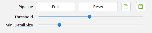
https://github.com/openpnp/openpnp/pull/1385
Also easier to copy OpenPnP stock pipelines to your pipelines, to
get new features etc.:
https://github.com/openpnp/openpnp/wiki/Computer-Vision#using-new-stock-pipelines
_Mark
To view this discussion on the web visit https://groups.google.com/d/msgid/openpnp/12a6367c-ef99-bc44-13a1-01865b24ccf5%40makr.zone.
Jan
Many thanks for the explaination! Today I tried both new features,
automatic background removal and pipline parameter exposer. Both works
very well for me.
However, I notice an unexpected feature removal by the first MaskHSV
state, I don't understand. Please find a few screenshots of the stock
pipeline using a TQFP44 attached. (I named them like their stage name)
The overall result is good, but between states 5 and 6 a lot of the leg
details seems to be lost. This is actually not a problem of the values,
that are applied. (Please find two more screenshots of a different
(larger) TQFP where I explicitely set all min values to 0 and all max
values to 255.) It seems, that saturations lower then about 70 are
masked to 0.
I assumed, that RGB to HSV transformation and back to RGB would be
fully transparent (without any loss of details/features). Did I missed
something?
Jan
On 24.02.2022 17:44, mark maker wrote:
> Hi Jan,
>
> To try the new pipeline with parameters...
>
> settings.
> 3. Then press the *Paste *button.
> 4. Give it a nice name.
> 5. Then go to a test Part or Package and assign it in the *BottomVision
> *column of the list:
>
>
> 6. Then*test it.*
> 7. If you're happy, you can assign the stock as the new default:
> 8. *NOTE*: I just found a bug there. The parameters do not appear
> <https://groups.google.com/d/msgid/openpnp/928656f9-6d22-5dcf-fbc5-2e93ef608afc%40makr.zone?utm_medium=email&utm_source=footer>.


mark maker
Hi Jan,
First of all these artifact are inconsequential, as you noticed
yourself.
The parts of your pins seem to exhibit a greenish cast, that
probably lies within the nozzle tip green range, that we can
glimpse through there. You haven't posted a background calibration
screenshot, but I would guess that your camera image (or actually
the LEDs) have a rather strong blueish-greenish cast (which I
guess is typical for such LEDs):

So I recommend following the White-Balance instructions fully, i.e. including the camera device settings:
https://github.com/openpnp/openpnp/wiki/Camera-White-Balance
Once they are properly tested, I will add these calibration steps
to Issues & Solutions, then I will also check if White
Balance is done prior to the background calibration.
_Mark
Jan
I see two issues:
a) even with hueMin/Max set to 0 and 255 something is masked by the
MaskHSV stage (see the image with .2 I attached in the previous e-mail) and
b) you're right, I did not apply white balance to the up-looking camera
yet. I tried with some white paper but that had to much reflectivity and
saturated the camera entire. Can you suggest any test object to use?
Jan
On 28.02.2022 16:20, mark maker wrote:
> Hi Jan,
>
>
> The parts of your pins seem to exhibit a greenish cast, that probably
> lies within the nozzle tip green range, that we can glimpse through
> there. You haven't posted a background calibration screenshot, but I
> would guess that your camera image (or actually the LEDs) have a rather
> strong blueish-greenish cast (which I guess is typical for such LEDs):
>
> *including the camera device settings*:
> https://github.com/openpnp/openpnp/wiki/Camera-White-Balance
>
> Then recalibrate the background, retest the pipeline, and report your
> findings back here.
>
> Once they are properly tested, I will add these calibration steps to
> *prior* to the background calibration.
> <https://groups.google.com/d/msgid/openpnp/3c9a44ad-64fc-2aea-9066-670956607d1e%40makr.zone?utm_medium=email&utm_source=footer>.
mark maker
> Can you suggest any test object to use?
I found brushed/sanded aluminium objects with faces oriented in
different direction, holes, shadows etc to be good. The animation
that you see on the Wiki
page is literally how I did it on my machine, just grabbed a
piece of aluminium lying around. Not rocket science.

Note, we 're not in portrait photography it does not need to be super-duper "true" to reality, we don't need naturally looking skin tones etc. 😎
However, (as you can imagine) if a greenish tint is present all
over, we will never succeed with MaskHsv for green screening. The
HSV model, or rather the bounding box we define on it, then simply
fails to be meaningful.
mark maker
> even with hueMin/Max set to 0 and 255 something is masked by the MaskHSV stage (see the image with .2 I attached in the previous e-mail)
It does not matter what you set in the MaskHsv stage
properties. It will be overridden by the Background Calibration.
If you do want to test manual stage control, either set the Background Calibration on the nozzle tip to None, press Accept and reopen the Pipeline Editor.
Or change the propertyName on the MaskHsv stage
to something other than "MaskHsv".
But please do not forget to change back
afterwards, or it won't work with Background Calibration
anymore, and we might be searching a long time for why the
heck...!?
_Mark
Jan
I've now applied some (Overall/Brightest) white balance and adjusted
the color temperature of the camera for best match. It seems, that the
stock lighting for the bottom camera has very little red and I found,
that the best mixture is for a color temperature of 6500k.
I then repeated the calibration and checked the alignment again. Works
way better now. Thanks for your suggestion to check the white balance.
However, I noticed two things with respect to the nozzle tip calibration:
a) for large nozzle tips like 506 (I use for the 10x10mm TQPF) the
procedure always complains that the inner part is not black enough. This
part is never visible for any bottom vision operation as its used to
hold the part. And my tries to make it more black using a sharpie
results in the opposite. The freshly colored part reflects even more.
Juki specifies a minim part diameter of 4mm for this nozzle. I'd suggest
to add an inner mask to the pipeline to remove stuff, that's not
relevant of the vision operation. Or even better, do not complain about
stuff, that's insight of the greenish part to be masked out.
b) for small nozzle tips and small components, the inner ring close to
the black center part is more relevant then the outer part. The
automatic calibration should respect that. Please find two images of the
alignment of a SOT-23 and the nozzle background calibration results
attached. There is a small halo around the legs after the masking, which
results in rotation errors. If I change the tolerance for Hue to 40 (20
is not enough, I've not checked other values) the pins are better
separated from the nozzle background.
Jan
On 28.02.2022 17:42, mark maker wrote:
> /> Can you suggest any test object to use? /
> I found brushed/sanded aluminium objects with faces oriented in
> different direction, holes, shadows etc to be good. The animation that
> you see on the Wiki page
> lying around. Not rocket science.
>
> <https://groups.google.com/d/msgid/openpnp/583995b0-a34e-0579-4ee4-0de557a430fd%40makr.zone?utm_medium=email&utm_source=footer>.


Jan
signals, that this stage is controlled exernally, like grayed out or
disabled. Might be also a worth mentioning that in the wiki. You could
also overwrite the values before the pipeline is opend, so that the user
can see the values that are active.
Jan
On 28.02.2022 17:52, mark maker wrote:
> /> even with hueMin/Max set to 0 and 255 something is masked by the
> MaskHSV stage (see the image with .2 I attached in the previous e-mail)/
>
> It does not matter what you set in the *MaskHsv* stage properties. It
>
> Background Calibration on the nozzle tip to *None*, press Accept and
> reopen the Pipeline Editor.
>
> Or change the *propertyName* on the *MaskHsv* stage to something other
>
> But please do not forget to change back afterwards, or it won't work
> with Background Calibration anymore, and we might be searching a long
> <https://groups.google.com/d/msgid/openpnp/1aed4221-f4d7-645a-50db-246fd6da4253%40makr.zone?utm_medium=email&utm_source=footer>.
mark maker
> ... the procedure always complains that the inner
part is not black enough. This part is never visible for any
bottom vision operation as its used to hold the part. ...
Juki specifies a minim part diameter of 4mm for this
nozzle.
Thanks for testing and the feedback!
First: the problem indication is just for you to optimize
things, i.e. you are free to ignore it! The Key Color (green
range) recognition is not disrupted by these spots and the MaskHsv
bounding box does not include them (that's exactly how they are
indicated, btw.). If what you say is true ("This part is never
visible for any bottom vision operation"), then the pipeline
and the background removal will still work 100% correctly.
But having said that, I know people don't like indicated
problems, even if they are false positives 😁 So let's aim
to eliminate these.
I did not know how this works for the Juki nozzle tips, I only
know the Samsung CP40 I tested, which seem to be entirely
different, i.e. their inner hole is always almost as large as the
outer rim, i.e. we can use the Vision Diameter plus some
margin, to blot out the center part.
The Wiki said:
The background calibration automatically blots out the center piece in the calibration image, where the nozzle tip was detected. This will eliminate any shiny elements that are typically present (needles, scraped off points etc.). OpenPnP assumes this center part to be always covered by the picked part, i.e. there is no need to include its color in the background calibration, nor these shiny elements treated as a problem (see Trouble Shooting). The blotted-out disc has a size of Vision Diameter + 2 x Minimum Detail Size (see Configuration).
So instead of the "Vision Diameter + 2
x Minimum Detail Size" formula, we
need to add a separate new Minimum Part Diameter
field to control the blotting-out diameter.
I was hoping to get away without adding yet another diameter field... 😉
> I'd suggest to add an inner mask to the pipeline to
remove stuff, that's not relevant of the vision operation.
If you say the part "is never visible for any bottom vision
operation", then there is no need to remove inside the
pipeline. However for the calibration (i.e. without any part on
the nozzle tip), the center part is already blotted-out, we only
need to make it larger/controllable via a separate diameter field.
> Or even better, do not complain about stuff, that's
insight of the greenish part to be masked out.
Not sure if that is always a good idea. There are small tips that might show when the part is picked off-center. By specifying the blotting-out diameter, both cases can be covered.
I know the following example is a CP40 nozzle tip (not green) but
couldn't the same happen for a Juki?

mark maker
> guess it would be a good idea to add some kind of lock
button that signals, that this stage is controlled exernally,
like grayed out or disabled.
Like I wrote before, I don't know how. The used property table is
an external Java class, that appears clunky to me. Plus it would
be quite a huge effort, there are many such built-in property
overrides.
> You could also overwrite the values before the pipeline is opend, so that the user can see the values that are active.
Well, it does in the case of the Exposed
Pipeline Parameters. But not in case of built-in
control.
In case of the Parameters it is involved, because after use, the
pipeline needs to be restored to the default values, otherwise the
Pipeline will be marked as modified. The same restore
operation would be needed for built-in control, so this would not
be trivial to implement (needs a backup).
My first aim is to make Pipeline Editing a thing of the past
for most of the users, which makes this a non-issue.
In the meantime: Pipeline Editing always was and always will be an expert topic. Experts need to know how to deal with such complexities. Finally, it is Open Source, and everybody is very welcome to step in there 😁
_Mark
Jan
On 01.03.2022 09:09, mark maker wrote:
[...]
> Samsung CP40 I tested, which seem to be entirely different, i.e. their
> inner hole is always almost as large as the outer rim, i.e. we can use
>
> The Wiki said:
>
> /The background calibration automatically blots out the center piece
> will eliminate any shiny elements that are typically present
> (needles, scraped off points etc.). OpenPnP assumes this center part
> to be always covered by the picked part, i.e. there is no need to
> Detail Size*//(see Configuration)./
>
> https://github.com/openpnp/openpnp/wiki/Nozzle-Tip-Background-Calibration#calibration-operating-principle/
> /
>
> So instead of the "/*Vision Diameter*//+ 2 x //*Minimum Detail Size*/"
> formula, we need to add a separate new *M**inimum Part Diameter* field
>
> I was hoping to get away without adding yet another diameter field... 😉
>
selected a smaller feature in the center of the nozzle tip for the
run-out calibration.
I always wonted to ask what the pros/cons are between Juki and Samsung
nozzles. To my limited understanding, the spring, that limited the Z
pressure, is part of the Samsung nozzle, while it's part of the Juki
nozzle tip.
Juki nozzles tips have a small inner core, that has a diameter of about
1mm. Depending on the nozzle tip size, different rubber caps are mounted
that actually touch the part. The 506 is designed for parts of at least
4mm diameter. Hence the rubber cap looks like a funnel with a ring of
about 3mm inner diameter and 1mm width that touches the part. I've set
the 3mm inner diameter as reference for the run-out calibration. I could
change that to the outer diameter, not sure that really helps.
Changing the min detail size is difficult as well. This large nozzle tip
is mainly used for tqfps/qfs/tssops all will sub-mm pitch pins that
require precise positioning and rotation...
> /
> /
>
> /> I'd suggest to add an inner mask to the pipeline to remove stuff,
>
> If you say the part /"is never visible for any bottom vision
> operation"/, then there is no need to remove inside the pipeline.
> the center part is already blotted-out, we only need to make it
> larger/controllable via a separate diameter field.
>
hence the part shields it from bottom vision. So for this 506, the
calibration should ignore the inner 5mm diameter...
> /
> /
>
> /> Or even better, do not complain about stuff, that's insight of the
> Not sure if that is always a good idea. There are small tips that
>
> I know the following example is a CP40 nozzle tip (not green) but
> couldn't the same happen for a Juki?
>
>
Did you missed an attachment/inline image here?
The rubber parts of small nozzle tips like 502 for 0402 is a rather
long funnel with a diameter of about 2.7mm at its largest (upper) end.
Due to the length and width, there is almost no surface, that can
reflect anything back into the camera. This back part is almost invisible.
At the upper end of the rubber part comes a green ring, that is used to
hold the spring. This ring is visible behind small parts on the nozzle
and has to be masked out. This ring is of great importance as its very
close to the part (with respect to the bottom cameras view).
Jan
> <https://groups.google.com/d/msgid/openpnp/a34df53f-2a15-3cf7-cbe7-e2b1b3dae44a%40makr.zone?utm_medium=email&utm_source=footer>.
mark maker
> Did you missed an attachment/inline image here?
In deed I did, sorry.
> The rubber parts of small nozzle tips like 502 for
0402 is a rather long funnel with a diameter of about 2.7mm at
its largest (upper) end. Due to the length and width, there is
almost no surface, that can reflect anything back into the
camera. This back part is almost invisible.

Yes it seems unproblematic, i.e. it will be included in the
"cutoff" darkness.
> At the upper end of the rubber part comes a green ring,
that is used to hold the spring. This ring is visible behind
small parts on the nozzle and has to be masked out. This ring is
of great importance as its very close to the part (with respect
to the bottom cameras view).
If it is green, it should be unproblematic.
Please send such an image, I do not see it in the ones you sent.
_Mark
Jan
On 01.03.2022 09:26, mark maker wrote:
[...]
> My first aim is to make Pipeline Editing a thing of the /past/ for most
>
> Finally, it is Open Source, and everybody is very welcome to step in
> there 😁
>
easy it now is to adjust the default pipeline for a tiny QFN with low
reflectivity on the legs. Adjusting the two sliders and the job was
already done.
Honestly, I have to admit, that I still opened the pipeline editor to
check the results of the MinAreaRect stage for stability. I personally
would like to have statistics on the alignment (for debugging and
adjustments only) to verify the stability with the new settings.
Speaking about vision pipelines: could you suggest any readings about
different pipeline types? If I understand the matter correctly, there
are three options: rectangular around outer structure (the default),
something using the pad geometry one can specify on package level and
pattern matching using some kind of reference. I haven't found anything
about the later two yet...
Jan
> <https://groups.google.com/d/msgid/openpnp/ade0d655-f415-f76d-796a-2f2b4fc2170a%40makr.zone?utm_medium=email&utm_source=footer>.
mark maker
> Speaking about vision pipelines: could you suggest any readings about different pipeline types?
I have never studied it formally.
> If I understand the matter correctly, there are three options: rectangular around outer structure (the default), something using the pad geometry one can specify on package level and pattern matching using some kind of reference. I haven't found anything about the later two yet...
Those are options, yes. The pad geometry you can implement in
OpenPnP right now, I believe, but I don't have a ready made
pipeline. The reference snapshot - teaching OpenPnP how the
package looks, and where the center is - would be a cool addition.
But because OpenPnP does not allow GUI interaction from the
machine thread, it would be cumbersome to implement "on demand
teaching" i.e. where OpenPnP would be prompting the user to teach
a new package on first sight, from inside a job. It would have to
interrupt the job and users would then have to restart it
afterwards. Cumbersome.
In addition to these well-known options, I will introduce my own
different idea/stage soon. 😁
_Mark
mark maker
> Honestly, I have to admit, that I still opened the
pipeline editor to check the results of the MinAreaRect stage
for stability. I personally would like to have statistics on the
alignment (for debugging and adjustments only) to verify the
stability with the new settings.
Of course we could run the pipeline 9 times with the Threshold
and Min.Detail parameters varied by some percentage (?)
around the mid-point in a "sensitivity analysis", i.e. assess
whether the same result will come out in all 9 settings, and if
not, fail the alignment. But that sounds awfully bloated and hard
to justify (and what percentage?).
Other ideas?
_Mark
Jan
> /> // Speaking about vision pipelines: could you suggest any readings
> about different pipeline types?/
> I have never studied it formally.
>
> pad geometry one can specify on package level and pattern matching using
> some kind of reference. I haven't found anything about the later two
> Those are options, yes. The pad geometry you can implement in OpenPnP
> right now, I believe, but I don't have a ready made pipeline. The
> reference snapshot - teaching OpenPnP how the package looks, and where
> the center is - would be a cool addition. But because OpenPnP does not
> allow GUI interaction from the machine thread, it would be cumbersome to
> implement "on demand teaching" i.e. where OpenPnP would be prompting the
> user to teach a new package on first sight, from inside a job. It would
> have to interrupt the job and users would then have to restart it
> afterwards. Cumbersome.
>
matching.
I'd love to understand what the pros/cons are. However, I did not
found any wikis, posts or anything else that explains, how
template-matching or this pad geometry version could be used. doppelgrau
has put some pipelines onto the wiki
(https://github.com/doppelgrau/openpnp/wiki/BottomVisionTemplates) but
no information how to use them or if/what benefit they have.
> In addition to these well-known options, I will introduce my own
> different idea/stage soon. 😁
>
Jan
> <https://groups.google.com/d/msgid/openpnp/bc95f1e9-c309-7d69-6d1d-3ee6392305cf%40makr.zone?utm_medium=email&utm_source=footer>.
Jan
> /> Honestly, I have to admit, that I still opened the pipeline editor
> personally would like to have statistics on the alignment (for debugging
>
> Of course we could run the pipeline 9 times with the *Threshold* and
> *Min.Detail* parameters varied by some percentage (?) around the
> result will come out in all 9 settings, and if not, fail the alignment.
> But that sounds awfully bloated and hard to justify (and what percentage?).
>
only. I personally would like to have a button like "Test Alignment"
that calls the pipeline a few times and represents the results as
mean/rms/max for position x/y, size x/y and rotation. At present I'd
say, that a good pipeline for a 0.5mm would have a rms error << 0.1mm
and an max error < 0.2mm. The allowable rotation error depends on the
size of the chip. Eg 10mm square tqfp housing -> 12mm outer diameter
pin-to-pin -> max 0.2mm/6mm radial error <=> max 1.9°.
A bad pipeline tuning would manifest in a large max. error and/or
larger rms error.
Jan
> <https://groups.google.com/d/msgid/openpnp/9667cb4c-ba9a-bc75-d3fc-87bf66c4bace%40makr.zone?utm_medium=email&utm_source=footer>.
mark maker
> I personally would like to have a button like "Test Alignment" that calls the pipeline a few times and represents the results as mean/rms/max for position x/y, size x/y and rotation.
I doubt that true instability of the pipeline is exposed with
that. Pipelines are typically repeatable, both when they're
"right" and when they are "wrong". I would bet any "rms"
that you see out of that comes almost entirely from the motion
system, i.e. backlash & Co.
The true "instability" is in suddenly not "seeing" some portion of the pins on some parts, because they are a bit duller than the threshold (set with a slightly shinier part), which results in the MinAreaRect "slipping" off. Or when the minimum detail size is too small to filter out a specific speck of dirt on the plastic body of the part, pulling the rectangle out.
These are "cliff edge effects", i.e. the detection either "slips off" dramatically, or not at all. They are hard to catch via statistics on one part. Statistics would have to be obtained over many part, but then they would only show how many are faulty, not very useful?
That's also why template image matching is so good. It is not
governed by edges, contours and other "black and white" i.e.
"cliff edge" stuff, but by the full-area probabilistic
measure of the most likely match. They don't care about "slightly
duller", or "specks of dirt" etc. the template still has an
extremely good probability to deliver the best match.
My new stage tries to eat some of that cake... but without having
to teach it templates in the first place.
I will probably present it tomorrow. 😁
_Mark
Jan
On 01.03.2022 15:14, mark maker wrote:
[...]
> /> At the upper end of the rubber part comes a green ring, that is used
> nozzle and has to be masked out. This ring is of great importance as its
> /
> If it is green, it should be unproblematic.
>
> Please send such an image, I do not see it in the ones you sent.
>
Yesterday I did run a longer job and did not found any problems with
the new pipeline design (incl. automatic background removal). For most
parts, I've used the default pipeline and for two I used specialized
ones. One is a connector with a large white body, that required a larger
threshold and the other a tiny QFN which had very dark pads and hence
required a smaller threshold. Worked very well, over all.
Concerning the SOT32-problem: I had the hue tolerance configured to 40
for its nozzle tip. I'll try to use the offline pipeline editor to reply
the images with the default tolerance and report.
Jan
PS: If you think the images I've recorded with the job could be helpful,
please let me know. I'm happy to share them.
> <https://groups.google.com/d/msgid/openpnp/6afa74c4-e9eb-b86f-a9cb-78c343d03378%40makr.zone?utm_medium=email&utm_source=footer>.
Jan
On 01.03.2022 18:48, mark maker wrote:
> /> //I personally would like to have a button like "Test Alignment" that
> I doubt that true instability of the pipeline is exposed with that.
> Pipelines are typically repeatable, both when they're "right" and when
>
> The true "instability" is in suddenly not "seeing" some portion of the
> pins on some parts, because they are a bit duller than the threshold
> (set with a slightly shinier part), which results in the MinAreaRect
> "slipping" off. Or when the minimum detail size is too small to filter
> out a specific speck of dirt on the plastic body of the part, pulling
> the rectangle out.
>
> These are "cliff edge effects", i.e. the detection either "slips off"
> dramatically, or not at all. They are hard to catch via statistics on
>
cameras noise that one can see, not much more...
> That's also why template image matching is so good. It is not governed
> by edges, contours and other "black and white" i.e. "cliff edge" stuff,
> template still has an extremely good probability to deliver the best match.
>
for bottom vision?
> My new stage tries to eat some of that cake... but without having to
> teach it templates in the first place.
>
leave just the pads visible... With pads are reference, this could be
more robust then just fitting a rectangular.
> I will probably present it tomorrow. 😁
>
I can provide move test images or test the pipeline...
Jan
> <https://groups.google.com/d/msgid/openpnp/09176a01-cedf-02d6-f13c-8cd49d7f00ad%40makr.zone?utm_medium=email&utm_source=footer>.
mark maker
> If you think the images I've recorded with the job could be
helpful, please let me know. I'm happy to share them.
Absolutely!