VFD filament drive
303 views
Skip to first unread message

Paul Andrews
Aug 20, 2021, 12:58:17 PM8/20/21
to neonixie-l
I'm designing a clock for DT-1704 tubes and am stumbling at the filament drive stage. They want 1.6V. I want to power it from 5VDC. I've tried wiring them in series, but there is a noticeable brightness gradient if I do. I've tried powering them using a LM4871 to generate a square wave with 1.6V RMS, but the voltage drops as I add more tubes in parallel (an aside: why is this? I know it is specified to drive a 4 Ohm to 8 Ohm load, so I assume that is it). I don't want to dump a bunch of heat through a LDO or a stack of diodes. So I looked at making a buck converter.
If at all possible I would like to re-use the design for other VFDs, e.g for VFDs that want a grid to be pulled below the VFD voltage, and I would really prefer to use AC rather DC so I can use it for multi-digit VFD tubes.
I thought that if I made the buck converter output isolated I would end up with a solution that would be more re-usable for different kinds of VFDs, but naturally I hit the issue of what off-the-shelf transformer I could use. I also got to thinking that the output diode of a buck converter that produces 1.6V is going to drop a significant part of the total voltage, which made me wonder why I should even try to rectify and smooth the output given that an AC filament voltage would be better anyway. Then I also wondered if such a solution would hit the same problem as the LM4871 design, i.e. dropping voltage as I add more tubes in parallel.
So I would appreciate any suggestions for what direction I should take here. I have too many options and no clear criteria.

Audrey
Aug 20, 2021, 1:01:27 PM8/20/21
to neoni...@googlegroups.com
Sorry for not being helpful, but I'd love to see your digivac clock when you're done!
--
You received this message because you are subscribed to the Google Groups "neonixie-l" group.
To unsubscribe from this group and stop receiving emails from it, send an email to neonixie-l+...@googlegroups.com.
To view this discussion on the web, visit https://groups.google.com/d/msgid/neonixie-l/860d4d78-c807-415e-a740-b576a4b5d18cn%40googlegroups.com.

gregebert
Aug 20, 2021, 1:25:20 PM8/20/21
to neonixie-l
I used a 2.5VAC transformer for my NIMO clock, and use series dropping resistors to get the correct current. Those filaments run at 1.1 VAC and 200mA. Using AC cancels-out the brightness quirks when using DC. The series resistor will reduce the power-on current surge and therefore extend the filament life, at the expense of added power. Finally, at least with the NIMO tubes, I have individual series fuses, along with logic and software to monitor the condition of the filaments, resistors, and fuses [yeah, yeah, it's overkill, but I had a lot of fun designing it....]
I do have several VFDs waiting for me to design clocks for them...just need the time.

Toby Thain
Aug 20, 2021, 1:48:46 PM8/20/21
to neoni...@googlegroups.com, Paul Andrews
On 2021-08-20 12:58 p.m., Paul Andrews wrote:
> I'm designing a clock for DT-1704 tubes and am stumbling at the filament
> drive stage. They want 1.6V. I want to power it from 5VDC. ...
> I'm designing a clock for DT-1704 tubes and am stumbling at the filament
>
FWIW I've used LM2575 1A adjustable step down for DC filament voltages
in that range.
--Toby
> ...
>
> So I would appreciate any suggestions for what direction I should take
> here. I have too many options and no clear criteria.
>
> So I would appreciate any suggestions for what direction I should take
> here. I have too many options and no clear criteria.
>
> --
> You received this message because you are subscribed to the Google
> Groups "neonixie-l" group.
> To unsubscribe from this group and stop receiving emails from it, send
> an email to neonixie-l+...@googlegroups.com
> <mailto:neonixie-l+...@googlegroups.com>.
> You received this message because you are subscribed to the Google
> Groups "neonixie-l" group.
> To unsubscribe from this group and stop receiving emails from it, send
> an email to neonixie-l+...@googlegroups.com
> To view this discussion on the web, visit
> https://groups.google.com/d/msgid/neonixie-l/860d4d78-c807-415e-a740-b576a4b5d18cn%40googlegroups.com
> <https://groups.google.com/d/msgid/neonixie-l/860d4d78-c807-415e-a740-b576a4b5d18cn%40googlegroups.com?utm_medium=email&utm_source=footer>.
> https://groups.google.com/d/msgid/neonixie-l/860d4d78-c807-415e-a740-b576a4b5d18cn%40googlegroups.com

Hannah Mishin
Aug 20, 2021, 3:37:46 PM8/20/21
to neoni...@googlegroups.com, Paul Andrews
Theres a section on filament driving in my blog here:
To unsubscribe from this group and stop receiving emails from it, send an email to neonixie-l+...@googlegroups.com.
To view this discussion on the web, visit https://groups.google.com/d/msgid/neonixie-l/ce44816f-120e-abae-060f-fe062d24f836%40telegraphics.com.au.

Dekatron42
Aug 20, 2021, 5:51:17 PM8/20/21
to neonixie-l
There is a nice article in NutsVolts magazine: http://www.nutsvolts.com/media-files/Forum-Articles/QA_201110.pdf where a powerful driver is shown, needs a small transformer but seems to be well designed with equations for calculations of the transformer.
/Martin

Adrian Godwin
Aug 20, 2021, 6:04:30 PM8/20/21
to neonixie-l
I mean to try this on a device I'm building, but won't an H-bridge driver do ?
It will provide an average potential of half the drive voltage giving the ability to place a grid or anode at a small negative potential, and if the filament requirement is less than the easy 5V it can be reduced using PWM by floating the H-bridge. Higher or lower average acceleration voltages can be accommodated by setting both ends of the filament to 0 or 5 during the off-period
.
To view this discussion on the web, visit https://groups.google.com/d/msgid/neonixie-l/a540fc31-ccde-4686-9c05-06a3c234c19dn%40googlegroups.com.

John Rehwinkel
Aug 20, 2021, 6:11:50 PM8/20/21
to 'David Weiner' via neonixie-l
>
> I'm designing a clock for DT-1704 tubes and am stumbling at the filament drive stage. They want 1.6V. I want to power it from 5VDC. I've tried wiring them in series, but there is a noticeable brightness gradient if I do.
I'm a big fan of series resistors (one per tube). It's inefficient, but low parts count, and gives a soft start to the filament. Another approach is current regulators or the aforementioned AC drive with a capacitive dropper.
> I'm designing a clock for DT-1704 tubes and am stumbling at the filament drive stage. They want 1.6V. I want to power it from 5VDC. I've tried wiring them in series, but there is a noticeable brightness gradient if I do.
- John
Paul Andrews
Aug 23, 2021, 11:49:01 AM8/23/21
to neonixie-l
Thanks Martin,
I'm OK with using a transformer. I would prefer something off the shelf, but perhaps I should just wind my own anyway. Seems like a useful skill to have.
As with a lot of these things, I find that I have a lot of questions. For example, this statement:
"The transformer is 1:1,
center-tapped. Since the
output is to be 300 mA max, the magnetizing current at the
input should be no more than 30
mA. I will try 10 mA"
First of all, how does he get a 10:1 ratio of output current to 'maximum magnetizing current'. Second, what is 'magnetizing current', does he just mean current through the primary?
Then he introduces terms in equations without defining them - they are probably obvious to the initiated (which I am not unfortunately). For example, Xl in
L = Xl/2/PI/F and Al in
N =
(L*1e6/Al)^.5. Then having calculated the required number of turns, he just ignores that and goes with something much larger.
gregebert
Aug 23, 2021, 2:19:58 PM8/23/21
to neonixie-l
Transformers are not ideal, so even with zero load, they consume inductive current. Most of the energy gets returned to the AC line, but some of it gets dissipated as heat (winding resistance, and hysteresis). This is why unloaded wall transformers still get slightly warm.
You can measure the magnetizing current with multimeter.
---------------------------------------------------------------------------------------------------------------------------------------
Be warned that large transformers will have a startup surge current; I have an isolation transformer in my workshop that can supply 20A/120VAC. It has dual primaries, so I can run it from 120V or 240V. If I try to run it from 120V, even with no load, it almost always pops the 20A breaker for my workbench. So, I use 240V and even then I can hear the wires in the conduit vibrate for an instant when it's energized.
If you are worried about blowing the fuse in your multimeter when measuring the magnetizing current, it's good practice to use a variac to increase the line voltage starting from 0 volts into your transformer.

Tomasz Kowalczyk
Aug 24, 2021, 3:57:53 AM8/24/21
to neonixie-l
Did you try simple PWM? I once tried it, but didn't leave it on for long time, so I can't tell if it shortens the tube life or not, but by simple logic it shouldn't. For most of the time the cathode will be at the same potential. Also it's a nice method of elevating the cathode potential above negative segment/grid voltage to get rid of faint glow of off segments.

Bill Notfaded
Aug 25, 2021, 4:37:56 PM8/25/21
to neonixie-l
I'm kinda in the same boat Paul... VFD's hasn't really been my thing but figuring out how to drive some weird ones is a new hobby. I love your questions because it helps me figure out what I'm doing as well!
Bill
Bill Notfaded
Aug 25, 2021, 4:40:04 PM8/25/21
to neonixie-l
I also have some
DT-1704 so this is great! I have two clocks that use them as well.
Bill
Paul Andrews
Aug 25, 2021, 5:02:48 PM8/25/21
to neonixie-l
When I have time, I will try the driver at the link Martin gave (http://www.nutsvolts.com/media-files/Forum-Articles/QA_201110.pdf), but without the transformer initially. As far as I can tell, the transformer is just to make the VFD drive isolated so you can pull it up above ground.
Bill Notfaded
Aug 26, 2021, 6:33:12 AM8/26/21
to neonixie-l
Some of the vfd driver chips are what I was looking at initially.
Bill
Dekatron42
Aug 27, 2021, 8:45:56 AM8/27/21
to neonixie-l
Since transformers isn't my best area, I only have basic understanding of the intricacies but I have experimented some with different transformers in different cases like when driving Trochotrons and Dekatrons I decided to ask an acquaintance who has worked with transformers. His name is Ed Dinning, I got to know him over at the UKVRRR forum (UK Vintage Radio Repair and Restoration forum: https://www.vintage-radio.net/forum/), he told me you are welcome to contact him via me so that his email is somewhat protected - if you ask him anything related to the VFD-drivers it would be kind if you could post something here in this forum so we all can learn from it.
This is his answer to my question on what transformer to chose for the driver in the article, it sure helped me and I hope it helps anyone who wants to experiment with this driver:
"Hi Martin, as it operates about 50/100KHz virtually any ferrite should do. It should be a transformer type with no air gap.
The turns are normally based on the transformer equation for square waves
N= V/ 4 * F * B* Ae
N=turns, V=volts F=frequency,B= flux density, typically 200/250mT for a ferrite, Ae the centre pole area in M^2
The actual losses come out later on in the design process and are not part of the initial criteria
Copper sizing is normally based on 3A per mm^2 of cross sectional area
The
turns figure he gives looks about right for something like an RM10
core, or you could try an EE25 or an ETD29 core in sat F44 materials
ETD's are the core of choice for this type of application and should be readily available.
The
more turns that are used the lower the iron losses and the cooler the
core runs, but the copper losses increase unless fatter copper is used.
Skin effect will be of minor importance at your frequency
It
would also work on a normal laminated core at 50Hz which should not be
too big as you can run that at up to 1.5T flux density.
Regulation could be a normal type of regulator set for constant current.
Always many choices in Engineering
Cheers, Ed
Ed Dinning Retired Engineer"
/Martin
Paul Andrews
Aug 30, 2021, 9:59:42 AM8/30/21
to neonixie-l
I created the circuit in LTSpice so I could mess with various components and see how it affects things like frequency and wave form. Rings like crazy, so I added an RC snubber, which seemed to also necessitate tying the primary center tap to ground through a capictor/diode (I don't know if that is an artifact of the way LTSpice works, or something that is actually necessary). I copied this from the LT3999 demo board schematic.
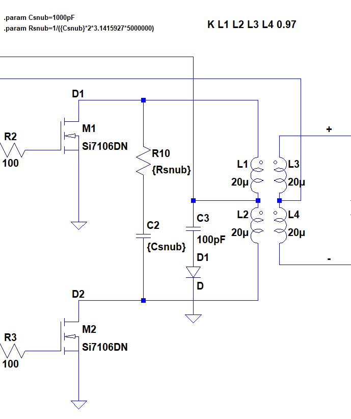
I was wondering about voltage sag with this, as there is no regulation and then re-read your post where Ed Dinning says "Regulation could be a normal type of regulator set for constant current". No idea what one of those might be, and whether he is just referring to the 50Hz solution or not.
gregebert
Aug 30, 2021, 11:55:49 AM8/30/21
to neonixie-l
The amount of ringing is usually load-dependent, and is primarily caused by the transformer being non-ideal. Changing the coupling factor from 0.99 to 0.95 should make quite a difference in the ringing. That wont necessarily reflect reality, but it does show you the effect it has. Also, it helps to include the DC resistance of the transformer windings.
I'm not a big fan of snubbers because they cause losses, and you need to be careful about how much current is going thru the capacitor. When I was tweaking the design of the DCDC converter for my NIMO clock, I was getting a thermal hot-spot on the snubber. After some careful adjustment of the duty-cycle and frequency I was able to reduce the ringing and the heat.
I implemented current-limiting in the drivers by adding a small resistance between the source and GND; I think it was about 3 ohms. The exact value is determined by the Vgs(on) of the MOSFET, your peak current, and the driving-voltage at the gate. Like the duty-cycle optimization, this was also done on the bench rather than the simulator.
Paul Andrews
Aug 31, 2021, 10:26:30 PM8/31/21
to neonixie-l
Hi Martin
I tried to find a suitable core at digikey, but their parameters don’t map very well to the equation that Ed gives. Could he take a look at what they have and perhaps recommend something. For simplicity’s sake I just looked at toroids https://www.digikey.com/en/products/filter/ferrite-cores/936?s=N4IgTCBcDaICoHsBOCCWATAhgGwAQGNkBTAZxAF0BfIA
Thanks - Paul
On Friday, August 27, 2021 at 8:45:56 AM UTC-4 Dekatron42 wrote:
Dekatron42
Sep 1, 2021, 1:55:30 AM9/1/21
to neonixie-l
Paul,
I'll ask him, but a quick search at Digikey showed both some RM10 and ETD29 cores, but only a few. Finding Ferrite cores today is not easy, I have searched some for other projects and they aren't usually stocked in the ranges that the manufacturers make them, and if you want something outside what is available in stock it becomes very expensive as you'll have to by thousands if not more. I usually try the ones they have and have to live with that since I can't buy the thousands needed to get the perfect one. I'll ask Ed to have a look and see if any of the ones that are stocked will do - just remember that they will have to be the transformer type without an airgap between the center pieces to work in this application.
/Martin
Paul Andrews
Sep 1, 2021, 9:11:31 AM9/1/21
to neonixie-l
Martin,
I wonder why there should be no air gap?
- Paul
Dekatron42
Sep 1, 2021, 9:57:43 AM9/1/21
to neonixie-l
You can use airgaps in transformers in some cases but this design should be without one according to Ed.
I am using ferrite pot cores in some other designs where they are wound as a transformer but where the Q-value is of importance and there I use an airgap and also a trimmer through the center to adjust them for a minimum Q-value at a certain frequency.
Q-value according to TDK: https://product.tdk.com/en/contact/faq/inductors-0003.html and also at Wikipedia: https://en.wikipedia.org/wiki/Q_factor
This article explains airgap in inductors/transformers somewhat: https://www.linkedin.com/pulse/why-do-we-provide-air-gap-usually-inductor-designs-transformer-p
So sometimes it is a choice depending on design criteria like Q-value and material used in the transformer. There are normal laminated transformers that use an airgap too, but most mains transformers do not.
/Martin

David Pye
Sep 1, 2021, 10:05:03 AM9/1/21
to neoni...@googlegroups.com
For mine I used one of those cheap eBay buck converters. 5v in, 1.x v out (adjustable). 8 iv11 tubes, running for a few years without a blip.
If you needed AC, you could always just use an H bridge and a microcontroller pin to flip it at a suitable frequency with a smoothing cap.
I found I couldn't have ordered the components cheaper than the finished eBay module...
David
--
You received this message because you are subscribed to the Google Groups "neonixie-l" group.
To unsubscribe from this group and stop receiving emails from it, send an email to neonixie-l+...@googlegroups.com.
To view this discussion on the web, visit https://groups.google.com/d/msgid/neonixie-l/8943cc8d-1219-44d0-9f19-62357cdf4951n%40googlegroups.com.
John Rehwinkel
Sep 1, 2021, 8:00:02 PM9/1/21
to neoni...@googlegroups.com
I wonder why there should be no air gap?
Air gaps lower the inductance, but stabilize it and store energy in the gap. Working forward from this, you generally find flyback type circuits use gapped cores, and others generally instead opt for best coupling and highest inductance.
- John
Reply all
Reply to author
Forward
0 new messages