Cone calorimeter test for Glass composite material

Thevakumar Thevega

Kevin McGrattan
Thevakumar Thevega
Kevin McGrattan
Thevakumar Thevega
Kevin McGrattan
Thevakumar Thevega
Kevin
SPECIFIC_HEAT=0.8,
CONDUCTIVITY=0.22,
DENSITY=1552.0,
ABSORPTION_COEFFICIENT=10.0,
HEAT_OF_COMBUSTION=1.62E+4,
N_REACTIONS=1,
HEAT_OF_REACTION=455.0,
SPEC_ID(1,1)='METHANE',
NU_SPEC(1,1)=0.05,
A=4.2,
E=1.75583E+4/
Thevakumar Thevega
Kevin McGrattan
Thevakumar Thevega
SPECIFIC_HEAT=0.8,
CONDUCTIVITY=0.22,
DENSITY=1552.0,
ABSORPTION_COEFFICIENT=10.0,
HEAT_OF_COMBUSTION=1.62E+4,
N_REACTIONS=1,
HEAT_OF_REACTION=455.0,
NU_MATL(1,1)=0.95,
SPEC_ID(1,1)='METHANE',
NU_SPEC(1,1)=0.05,
REFERENCE_TEMPERATURE=275.0,
HEATING_RATE=20.0,
PYROLYSIS_RANGE=250.0/
&MATL ID='Glass',
SPECIFIC_HEAT=0.84,
CONDUCTIVITY=0.8,
DENSITY=2500.0,
ABSORPTION_COEFFICIENT=10.0/
Also, is this data of the remaining material necessary to measure the heat release rate of the composite material?
Kevin McGrattan
Thevakumar Thevega
Kevin McGrattan
Thevakumar Thevega
&MATL ID='GCM',
SPECIFIC_HEAT=0.8,
CONDUCTIVITY=0.22,
DENSITY=1552.0,
HEAT_OF_COMBUSTION=1.62E+4,
N_REACTIONS=1,
HEAT_OF_REACTION=455.0,
MATL_ID(1,1)='Glass',
NU_MATL(1,1)=0.95,
SPEC_ID(1,1)='METHANE',
NU_SPEC(1,1)=0.05,
REFERENCE_TEMPERATURE=275.0,
Kevin McGrattan
Thevakumar Thevega
Thevakumar Thevega
Kevin McGrattan
Thevakumar Thevega
Thevakumar Thevega

dr_jfloyd
Thevakumar Thevega
Thevakumar Thevega

Khalid Moinuddin
Not all, if you are not prescribing your fire size.
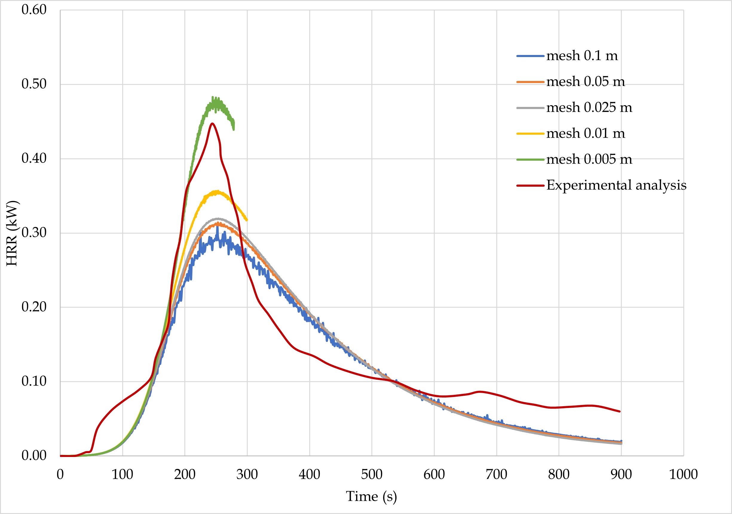
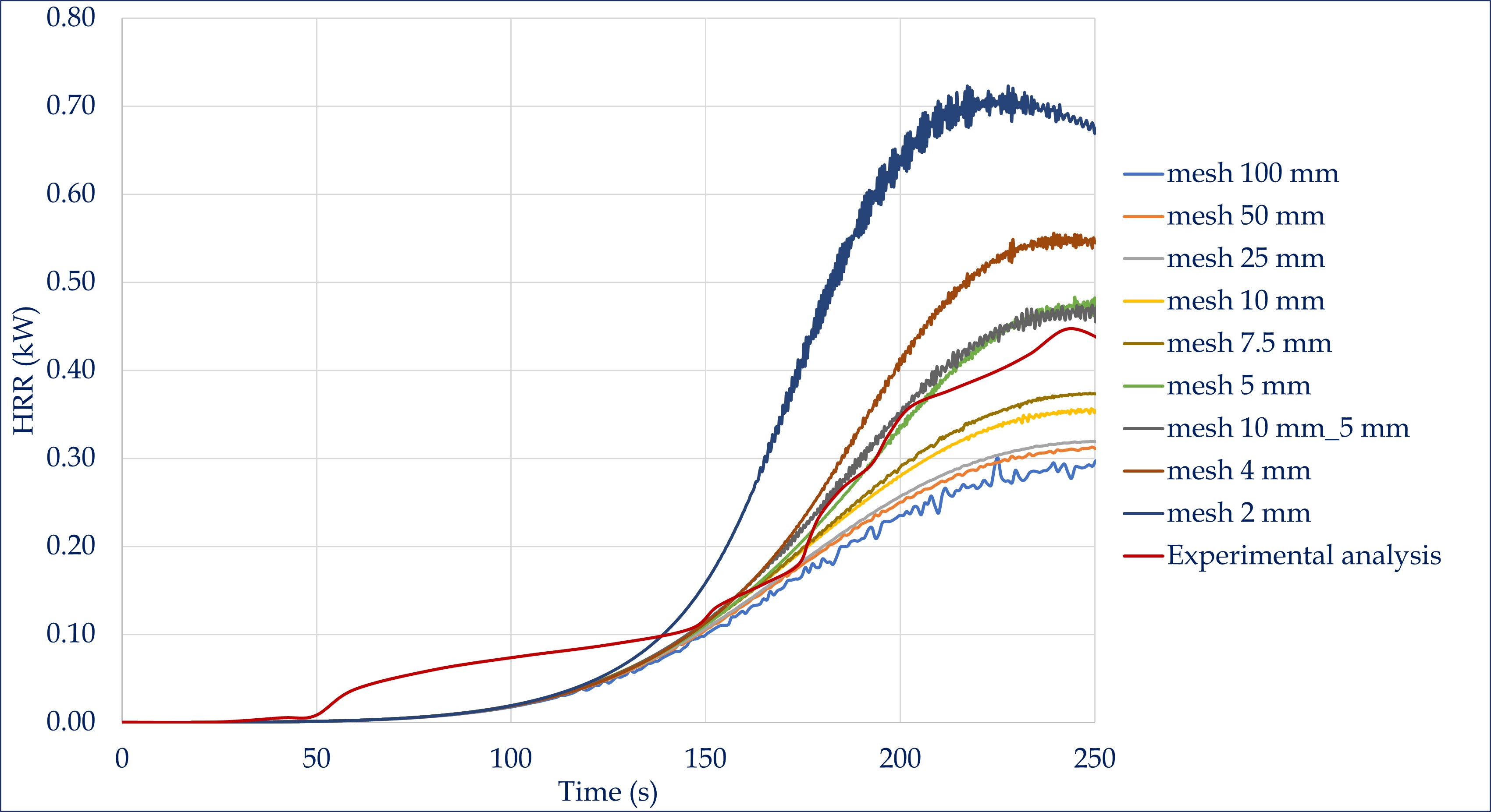
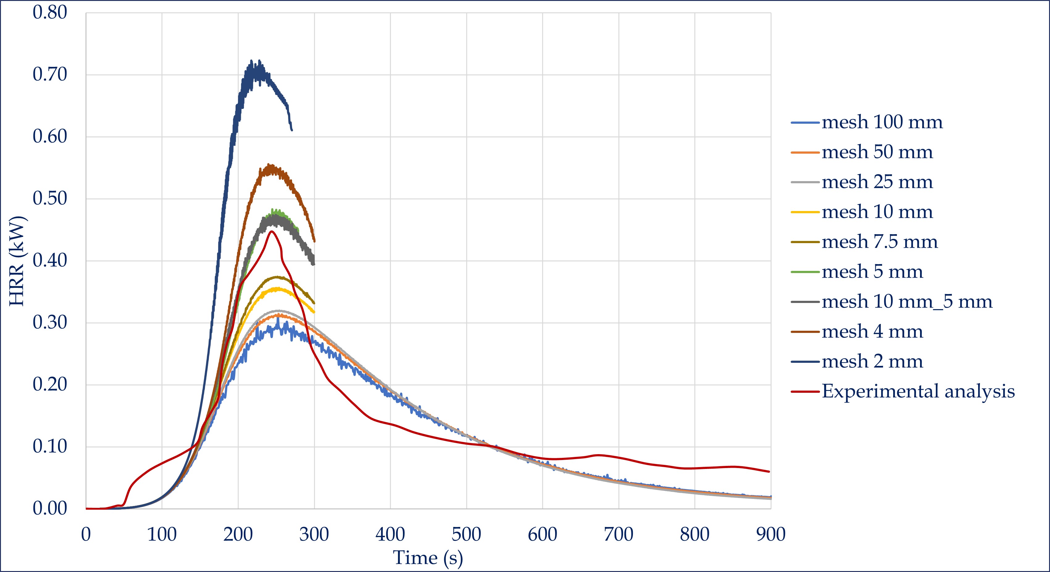
You need to compare your HRR vs time profile obtained with different meshes and continue to refine the meshes until HRR vs time profile converges.
From: fds...@googlegroups.com <fds...@googlegroups.com>
On Behalf Of Thevakumar Thevega
Sent: Monday, 12 September 2022 8:13 PM
To: FDS and Smokeview Discussions <fds...@googlegroups.com>
Subject: Re: [fds-smv] Cone calorimeter test for Glass composite material
EXTERNAL EMAIL: Please be cautious before clicking on any links or downloading attachments.
--
You received this message because you are subscribed to the Google Groups "FDS and Smokeview Discussions" group.
To unsubscribe from this group and stop receiving emails from it, send an email to
fds-smv+u...@googlegroups.com.
To view this discussion on the web visit
https://groups.google.com/d/msgid/fds-smv/17738941-ec7e-4b37-a563-1322cc6f250en%40googlegroups.com.
Kevin McGrattan
Thevakumar Thevega

Jonathan Hodges
--
You received this message because you are subscribed to the Google Groups "FDS and Smokeview Discussions" group.
To unsubscribe from this group and stop receiving emails from it, send an email to fds-smv+u...@googlegroups.com.
To view this discussion on the web visit https://groups.google.com/d/msgid/fds-smv/54a3b845-c368-49ac-9ac9-23071657f0f1n%40googlegroups.com.
Khalid Moinuddin
In terms of convergence criteria, for the quantitative approach, we use Grid Convergence Index (GCI).
Roache PJ, 1992. Quantification of uncertainty in computational fluid dynamics, Annual Review Fluid Mechanics, vol. 29:123–60
When the HRR is NOT prescribed, GCI can be calculated for the time-series of HRR. If the HRR is prescribed, it can be either time-history of temperature at any specific point or time-averaged temperature of a thermocouple tree.
Lower the GCI, closer/better the convergence. A GCI of 10%-20% will be really good.
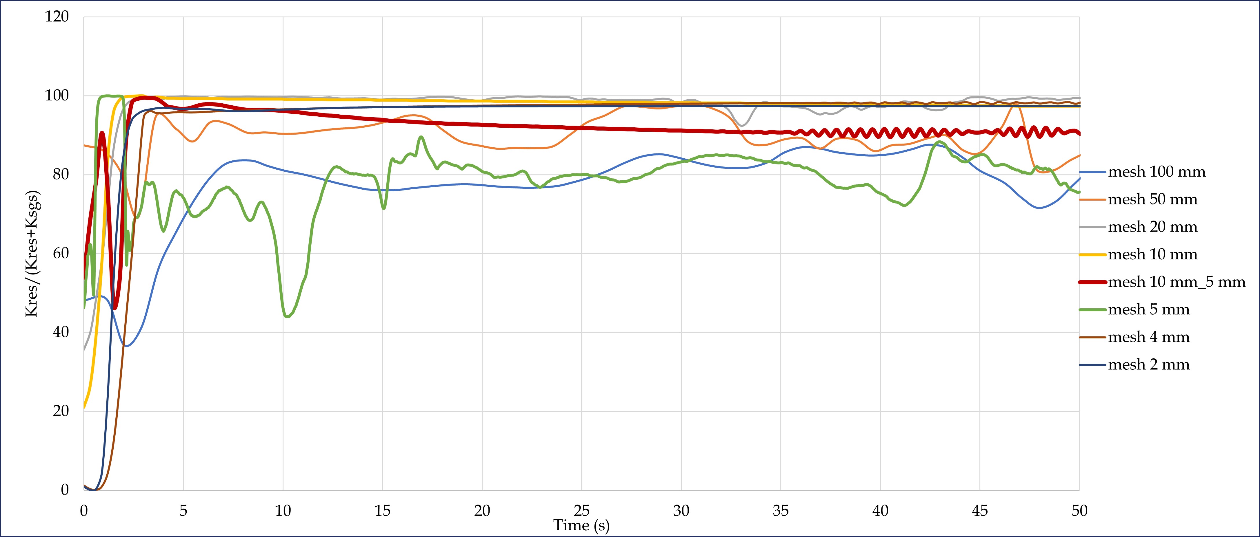
D*/dx relationship is only applicable for when the HRR is prescribed. 4 <D*/dx < 16 was based on Baungui et al (2003) where the HRR was prescribed. One of our Masters students conducted simulations of a set of prescribed fires in warehouses (different fire sizes and warehouse sizes). At different locations of the warehouse, they calculated measure of turbulence resolutions. 80% turbulence kinetic energy was generally resolved when D*/dx ~ 12.
We also tried to use D*/dx relationship when the HRR was NOT prescribed. For different fire sizes (cone calorimeter to forest fires), it ranged between 15 and 40. I don't recommend using D*/dx criteria when the HRR is NOT prescribed. One should not reduce, 20 mm to 2 mm in one jump. The preferred way is to use 20, 10, 5, 3.75, 2 mm (the ratio must be more than 1.3).
From: fds...@googlegroups.com <fds...@googlegroups.com> On Behalf Of Jonathan Hodges
Sent: Friday, 16 September 2022 8:38 PM
To: fds...@googlegroups.com
Subject: Re: [fds-smv] Cone calorimeter test for Glass composite material
EXTERNAL EMAIL: Please be cautious before clicking on any links or downloading attachments.
1. Are you using the default radiation angles? Increasing the radiation angles may increase your convergence without going to a finer grid.
2. Are you using the default number of time steps between recomputing radiation? As you are resolving your grid more, the time step is being reduced per the CFL condition. Since you have significant feedback between the flame and surface which is driving the pyrolysis, any artificial delays in the RTE calculation at the coarser scale will be reduced in the finer scale. But you could get a similar benefit by modifying this time step at the coarser grid without going to the fine grid.
3. Have you defined what your criteria for convergence is? You can keep resolving your mesh until you get to a sub millimeter grid and your answer will still change a bit. At some point you need to establish what is good enough for your application.
4. If the end goal of your analysis is to simulate a large fire, you aren't going to do that with a 2mm grid throughout your whole domain. If you are hoping to establish a D*/dx that works for your situation and then extrapolate that to a larger fire, I would caution that approach. The work we have done with SFPE has shown the D*/dx relationship for convergence is not great when you are looking at heat transfer from a local fire.
Jonathan
Thank you all.
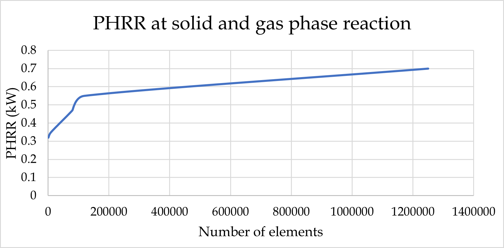
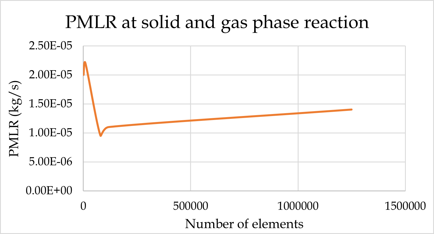
When I decreased the mesh size from 20 mm (D*/δ=2.5) to 2 mm (D*/δ=25), there are no grid convergence (peak heat release rate or peak mass loss rate) in the combined reaction (solid and gas phase reaction).
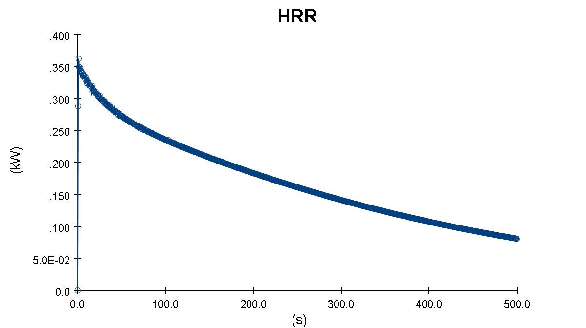
But the peak mass loss rate converged in the solid phase reaction. Because there are no fire simulations in the solid phase reaction.
Can I use the converged mesh size in the solid phase reaction for further analysis in the combined reaction?
The attached images are the grid convergence results for both conditions.
Thank you for your time.
Best Regards,
Thevega.
On Monday, September 12, 2022 at 4:19:44 PM UTC+5:30 Kevin wrote:
This range of 4 to 16 has become legend. It is not. We did a validation study 15 years ago and reported our range of D*/dx. That is all. In general, the larger the value, the better, but how much better depends on the case and a grid resolution study.
--
You received this message because you are subscribed to the Google Groups "FDS and Smokeview Discussions" group.
To view this discussion on the web visit https://groups.google.com/d/msgid/fds-smv/54a3b845-c368-49ac-9ac9-23071657f0f1n%40googlegroups.com?utm_medium=email&utm_source=footer.
You received this message because you are subscribed to the Google Groups "FDS and Smokeview Discussions" group.
To view this discussion on the web visit https://groups.google.com/d/msgid/fds-smv/CAG5CbNOTGzsingzMABxjXk98BZm5AeJ_W4XEUzQFXgzk9SHa8A%40mail.gmail.com?utm_medium=email&utm_source=footer.
Thevakumar Thevega
Thevakumar Thevega
Jonathan Hodges

Randy McDermott
To unsubscribe from this group and stop receiving emails from it, send an email to fds-smv+u...@googlegroups.com.
To view this discussion on the web visit https://groups.google.com/d/msgid/fds-smv/bda9df47-7d4d-4ab3-ad48-fa25cb3d999dn%40googlegroups.com.
Thevakumar Thevega
Thevakumar Thevega
Jonathan Hodges
Kevin
Thevakumar Thevega
Thevakumar Thevega
dr_jfloyd
Thevakumar Thevega
Thevakumar Thevega
Khalid Moinuddin
The FDS code is substantially changed since we did this study 15 years ago. We used FDS version 4. Now we have FDS version 6.7.9.
From: fds...@googlegroups.com <fds...@googlegroups.com>
On Behalf Of Thevakumar Thevega
Sent: Monday, 26 September 2022 9:02 PM
To: FDS and Smokeview Discussions <fds...@googlegroups.com>
Subject: Re: [fds-smv] Cone calorimeter test for Glass composite material
EXTERNAL EMAIL: Please be cautious before clicking on any links or downloading attachments.
When I search about LES and DNS mode, the gas phase reaction was also performed in LES mode and the grid size was converged. I have attached the referred literature. Could you please explain it?
--
You received this message because you are subscribed to the Google Groups "FDS and Smokeview Discussions" group.
To unsubscribe from this group and stop receiving emails from it, send an email to
fds-smv+u...@googlegroups.com.
To view this discussion on the web visit https://groups.google.com/d/msgid/fds-smv/f4d1ce2e-eba0-44ef-bf33-48f7c45c0f6fn%40googlegroups.com.
Thevakumar Thevega
Thevakumar Thevega
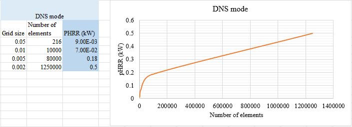
I performed the grid convergence while using DNS mode for the gas phase reaction. However, it does not converge to the smaller grid sizes (attached below).
When I reduce the grid size in LES mode, the measurement uncertainty of HRR is reduced. However, in DNS mode, it is high.
Also, I show a few recent studies in that researchers used LES mode for gas phase reaction and validated their results.
I am concerned that I may have overlooked anything in the fds numerical model. Could you please assist me in identifying that?
Kevin
Thevakumar Thevega
Kevin
Thevakumar Thevega
Kevin McGrattan
Thevakumar Thevega
dr_jfloyd
Thevakumar Thevega
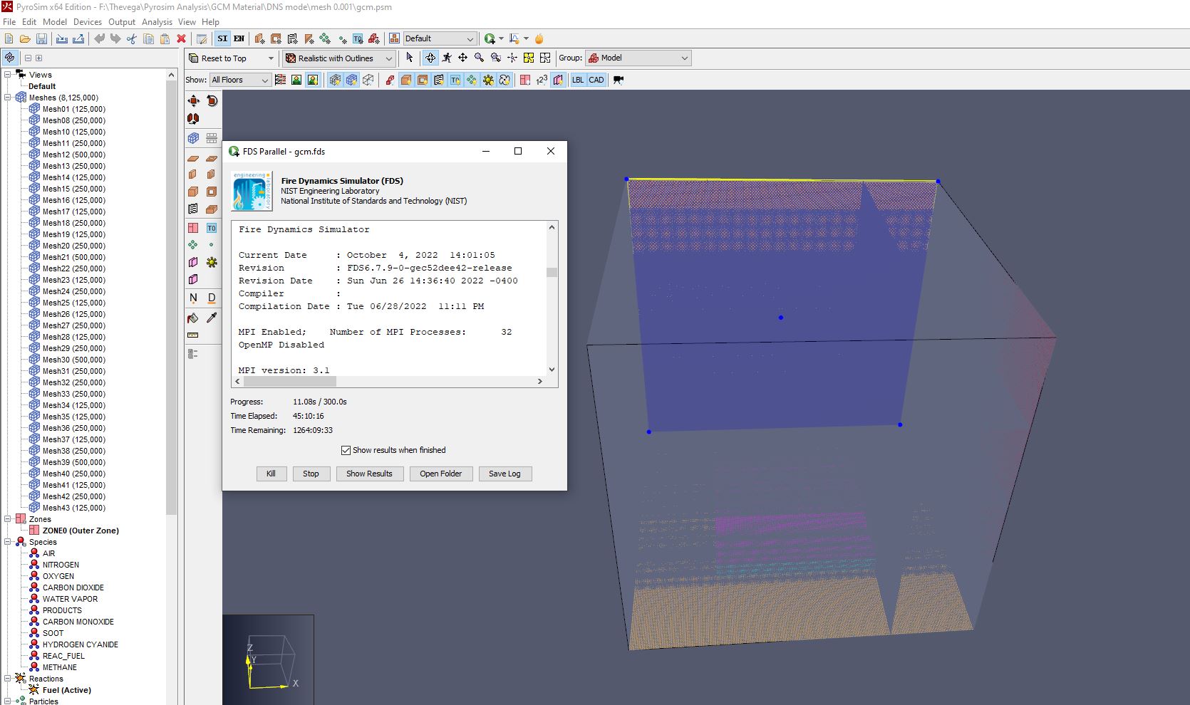
With a 1 mm mesh size, I can able to see the obstruction and vent in SMV view (attached figure). However, I will try with your suggestion and check the results.
dr_jfloyd
Thevakumar Thevega
1. The 10 mm grid size for PMMA polymer is converged and validated by experimental results. However, the outcome starts to deviate from the result of the 10 mm grid size when the grid size is progressively reduced.
2. For PBTGF material, grid sizes of 50 mm to 5 mm produce nearly identical HRR values.
3. The findings of my grid convergence for glass composite material started to diverge after 10 mm (the pHRR increases rapidly and the time for PHRR changes).