Holy Smokes! uTracer goes wireless!

nickb
UQ13yBRr-MO(g1Q~~60_58.JPG)

Nick de Smith
nickb
Nick de Smith
nickb

Nick B
Nick de Smith
Good news!
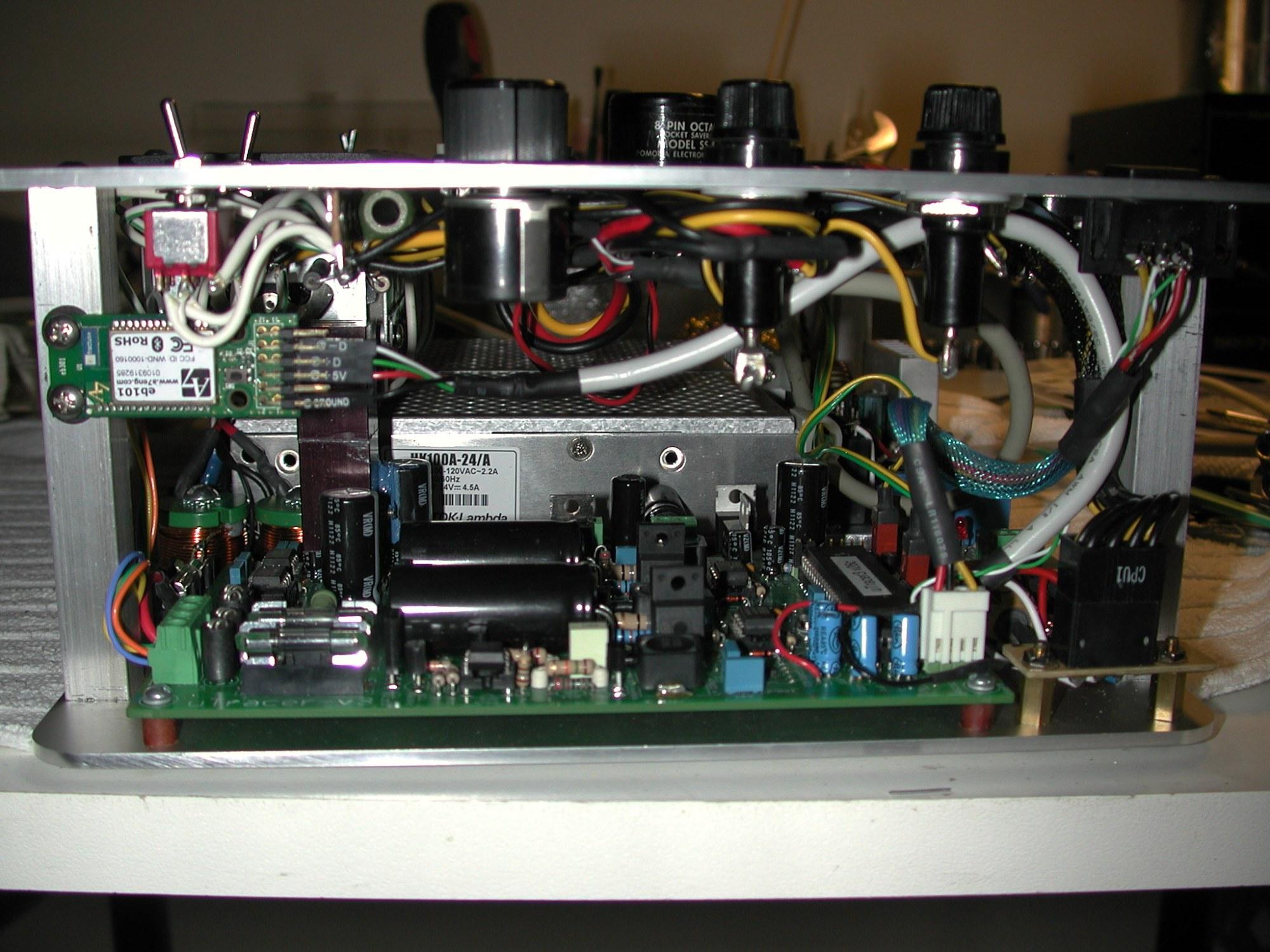
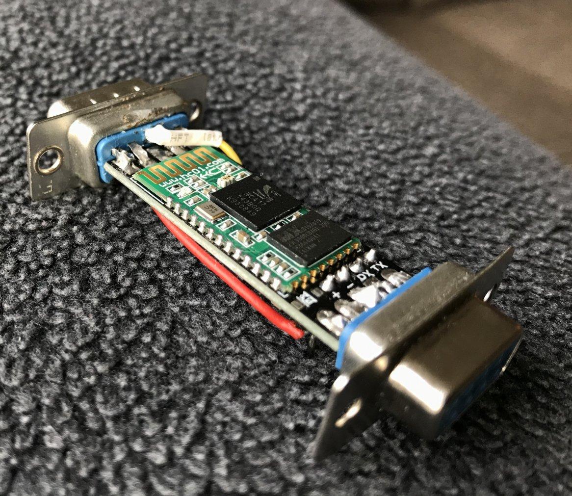
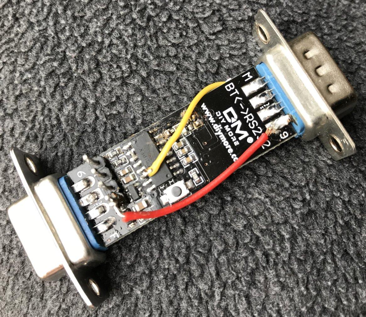
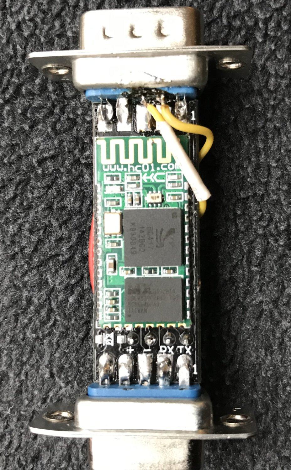
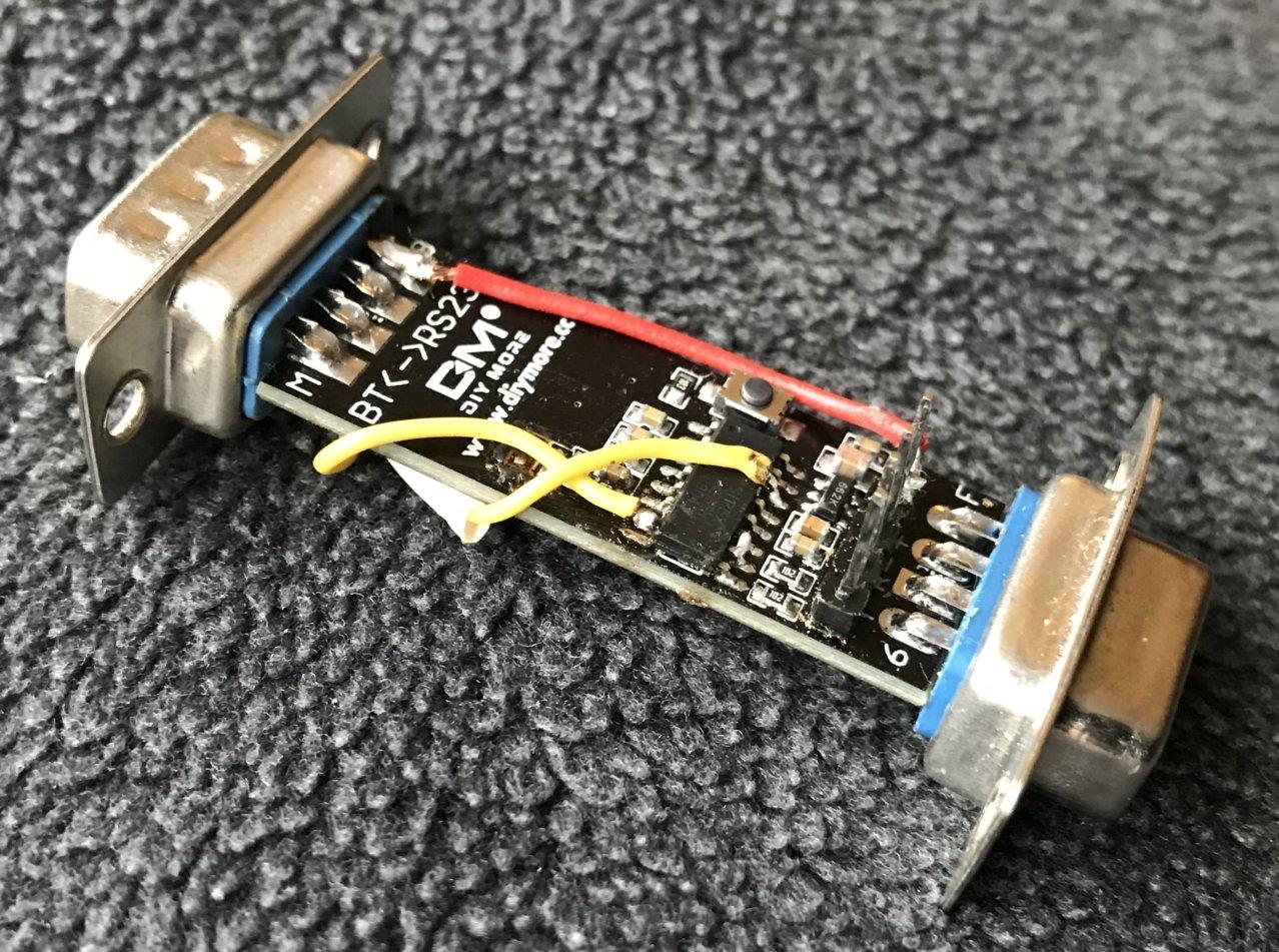
Works a treat with the nice level adapter card (whose pins line up conveniently). No changes to the uTracer PCB - just remove the MAX232 and use a pin header for 16,15,9 & 10. Don't seem to be any SMPS interference issues. I'm using Windows 7 64 bit with my laptop's built-in BT adapter - I tried a cheap dongle on a standard W7/64 mini-tower and windows didn't like the adapter, so if you don't have a built-in one, I'd use a decent quality dongle...
For the record, I was using this BT serial board : http://www.ebay.co.uk/itm/151057036889 and this 3.3V/5V level changer (make sure you connect the 3.3V side to the BT serial board!) : http://www.ebay.co.uk/itm/251208215004 . The BT board bonds with a default code of "1234" and serial characteristics of 9600,8,1,N.
Full galvanic isolation and remote access for about USD15./ GBP 10 :)
Hope you find this useful (and a way of protecting those expensive computers!)
Nick (de Smith)


Martin Manning
MPM
--
You received this message because you are subscribed to the Google Groups "uTracer" group.
To unsubscribe from this group and stop receiving emails from it, send an email to utracer+u...@googlegroups.com.
For more options, visit https://groups.google.com/groups/opt_out.
nickb
mman...@fuse.net
To: utr...@googlegroups.com
Sent: Thursday, September 19, 2013 8:15:39 PM
Subject: Re: Holy Smokes! uTracer goes wireless!
nickb

Mike Foo

Kevin Kennedy

mks...@gmail.com
A few interesting observations. Because there I both devices are connected in parallel, you must set the com port and hit the send escape button from the debug panel, otherwise the device may not always connect. Alternatively you may need power down the bluetooth board. I tried several variations, but I seemed to always have to hit the send escape to clear the devices and initiate communications. Even before going wireless, sometimes the uTracer gets locked up when communicated, and hitting the Send escape, clears the communication issues.
Another interesting phenomena is where you pick up power for the bleutooth wireless device. If you pull the 5V power/ground from the connections of the on-board MAX232 pins, the HV led may flicker or stay on. Interesting, I tried different power source configurations, when I connect the bluetooth ground wire to the negative power supply terminal, the problem disappeared. This also happened with a different bluetooth device I tried. So may be a grounding or noise issue on the uTracer board.
Nick de Smith
mks...@gmail.com
Mark

dmreese1
Laura Barton
--You received this message because you are subscribed to a topic in the Google Groups "uTracer" group.For more options, visit https://groups.google.com/d/optout.
To unsubscribe from this topic, visit https://groups.google.com/d/topic/utracer/oj7JzgMjolw/unsubscribe.
To unsubscribe from this group and all its topics, send an email to utracer+u...@googlegroups.com.
dmreese1
Duane
mks...@gmail.com
Mark
Martin Manning

Swamp FX Daniel esteves
I tried the bluetooth and It works great!
Used this cheap Bluetooth module:
http://store.nerokas.co.ke/image/cache/data/bluetooth-module-breakout-hc-05-500x500-600x600.png
HC05 from ebay
and followed the instructions of Ronald here:
http://dos4ever.com/uTracerNotebook/Notebook.html
My Com port on bluetooth is COM9, so only have to change this on the GUI.
Works Great! No cables anymore!

johnnyclin...@gmail.com
Any ideas on finding unit in US?
Thanks
Swamp FX Daniel esteves
--
You received this message because you are subscribed to a topic in the Google Groups "uTracer" group.
To unsubscribe from this topic, visit https://groups.google.com/d/topic/utracer/oj7JzgMjolw/unsubscribe.
To unsubscribe from this group and all its topics, send an email to utracer+u...@googlegroups.com.
For more options, visit https://groups.google.com/d/optout.


0221...@charter.net
I am in the process of purchasing a uTracer from Ronald, and I am hoping for clarification on including Bluetooth. In using the FTDI TTL-232R-5V or -WE cable, Could I just use a USB dongle plugged into the cable end? Unfortunately, my electronics training stopped in the early '70's and it doesn't extend to semiconductors and computer logic stuff. I know enough to get myself in trouboe, that's all. Any assistance would be deeply appreciated. Kind Regards, Joe Rossi
mman...@fuse.net
To: "uTracer" <utr...@googlegroups.com>
Sent: Sunday, June 4, 2017 9:45:04 PM
0221...@charter.net
Swamp FX Daniel esteves
http://dos4ever.com/uTracerNotebook/Notebook.html#USB
http://www.ebay.com/itm/BT06-Bluetooth-Serial-Port-Wireless-Data-Module-Compatible-With-HC-06-1Pc-/132166930345?hash=item1ec5c34fa9:g:FfoAAOSwImRYP5pT
To unsubscribe from this group and stop receiving emails from it, send an email to utracer+unsubscribe@googlegroups.com.
For more options, visit https://groups.google.com/d/optout.
--
You received this message because you are subscribed to a topic in the Google Groups "uTracer" group.
To unsubscribe from this topic, visit https://groups.google.com/d/topic/utracer/oj7JzgMjolw/unsubscribe.
To unsubscribe from this group and all its topics, send an email to utracer+unsubscribe@googlegroups.com.
0221...@charter.net
For more options, visit https://groups.google.com/d/optout.
--
You received this message because you are subscribed to a topic in the Google Groups "uTracer" group.
To unsubscribe from this topic, visit https://groups.google.com/d/topic/utracer/oj7JzgMjolw/unsubscribe.
To unsubscribe from this group and all its topics, send an email to utracer+u...@googlegroups.com.
Swamp FX Daniel esteves
To unsubscribe from this group and all its topics, send an email to utracer+unsubscribe@googlegroups.com.

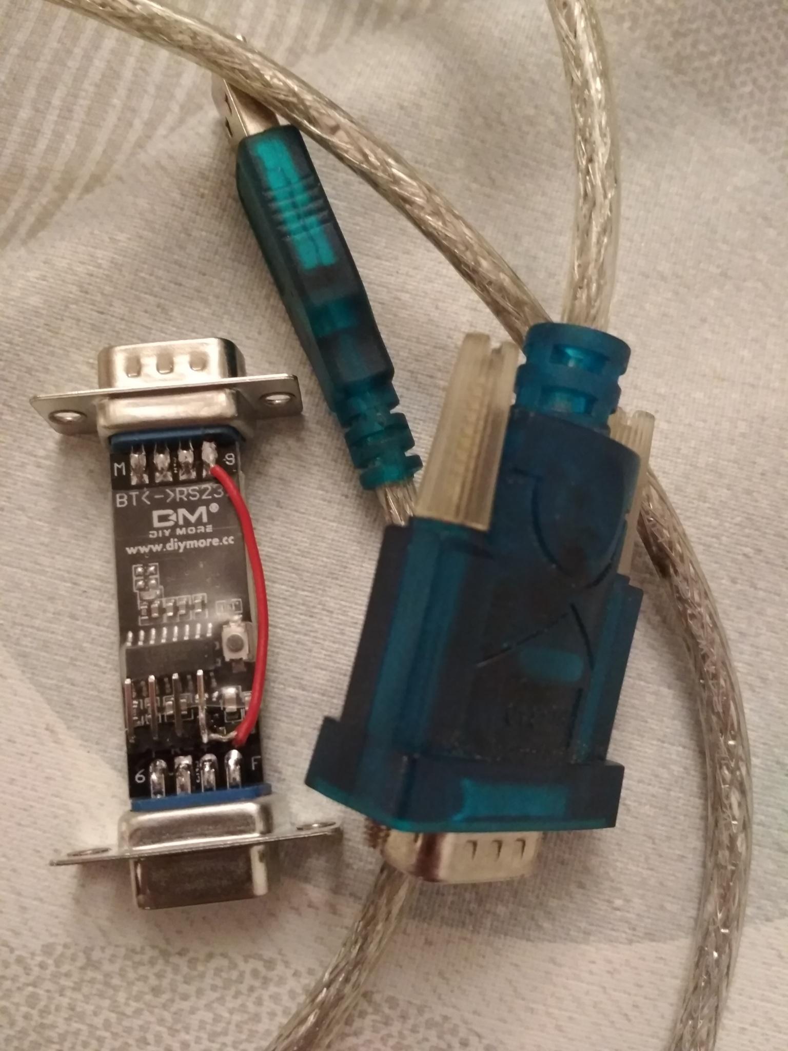
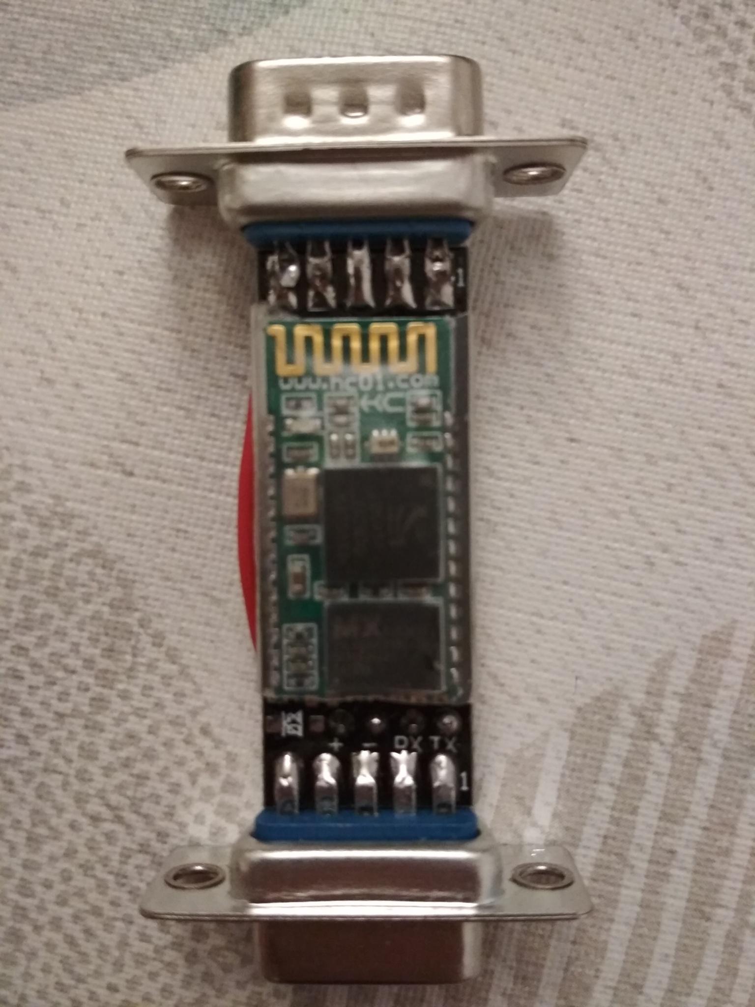
Ihor
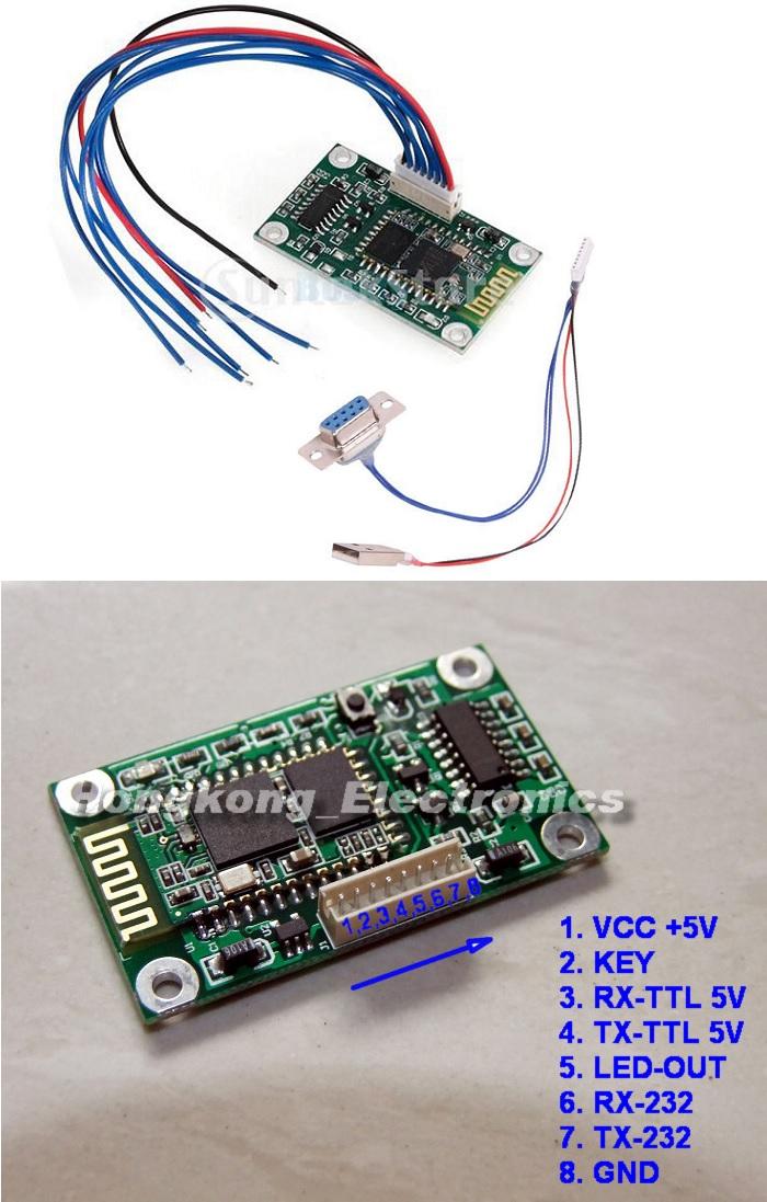
– baud rate = 9600
– password = 1234
– nl/cr line endings not required (???)
– AT commands are required to be in upper case
– Firmware version = hc01.comV2.0
– Name = HC-06
– No parity
– SLAVE mode
On Saturday, July 27, 2013 at 2:14:34 AM UTC+2, nickb wrote:
Here's an alternative to those usb to serial adapters: Bluetooth to serial. I just ordered one to try out for $7. Goodbye pesky wires!

I'll let you know how it works out.Nick B
Ihor
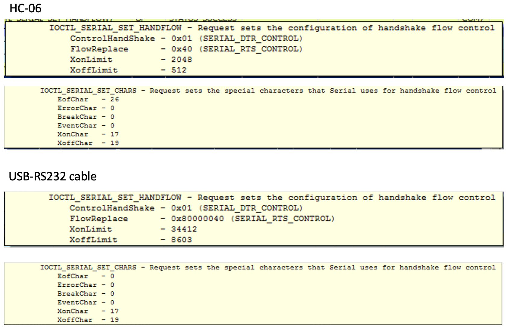
The EOF (end of file) character. Receipt of this character marks the end of the input stream.
So, probably that "improvement" in the newest firmware of HC-06 ("– nl/cr line endings not required") messes up the whole thing.

Big Josh
--
You received this message because you are subscribed to the Google Groups "uTracer" group.
To unsubscribe from this group and stop receiving emails from it, send an email to utracer+u...@googlegroups.com.
To view this discussion on the web visit https://groups.google.com/d/msgid/utracer/f371acd9-1f4f-4c67-9551-d7920dbde5d6%40googlegroups.com.
Ihor
Big Josh
--
You received this message because you are subscribed to the Google Groups "uTracer" group.
To unsubscribe from this group and stop receiving emails from it, send an email to utracer+u...@googlegroups.com.
To view this discussion on the web visit https://groups.google.com/d/msgid/utracer/f734f34c-9cfc-4ba7-903c-de6e81d1fb55%40googlegroups.com.
Ihor
Ihor
To unsubscribe from this group and stop receiving emails from it, send an email to utr...@googlegroups.com.
Ihor
Ihor

PSchaefer

Thomas Mayfield
Sent: Monday, January 6, 2020 9:54:49 AM
To: uTracer <utr...@googlegroups.com>
Subject: Re: Holy Smokes! uTracer goes wireless!
You received this message because you are subscribed to the Google Groups "uTracer" group.
To view this discussion on the web visit https://groups.google.com/d/msgid/utracer/22f23ab2-99bb-40b3-b46c-2eaf2135ace2%40googlegroups.com.
Ihor
To clarify the situation a bit and to document those things for myself, I made a small diagram.
Ihor
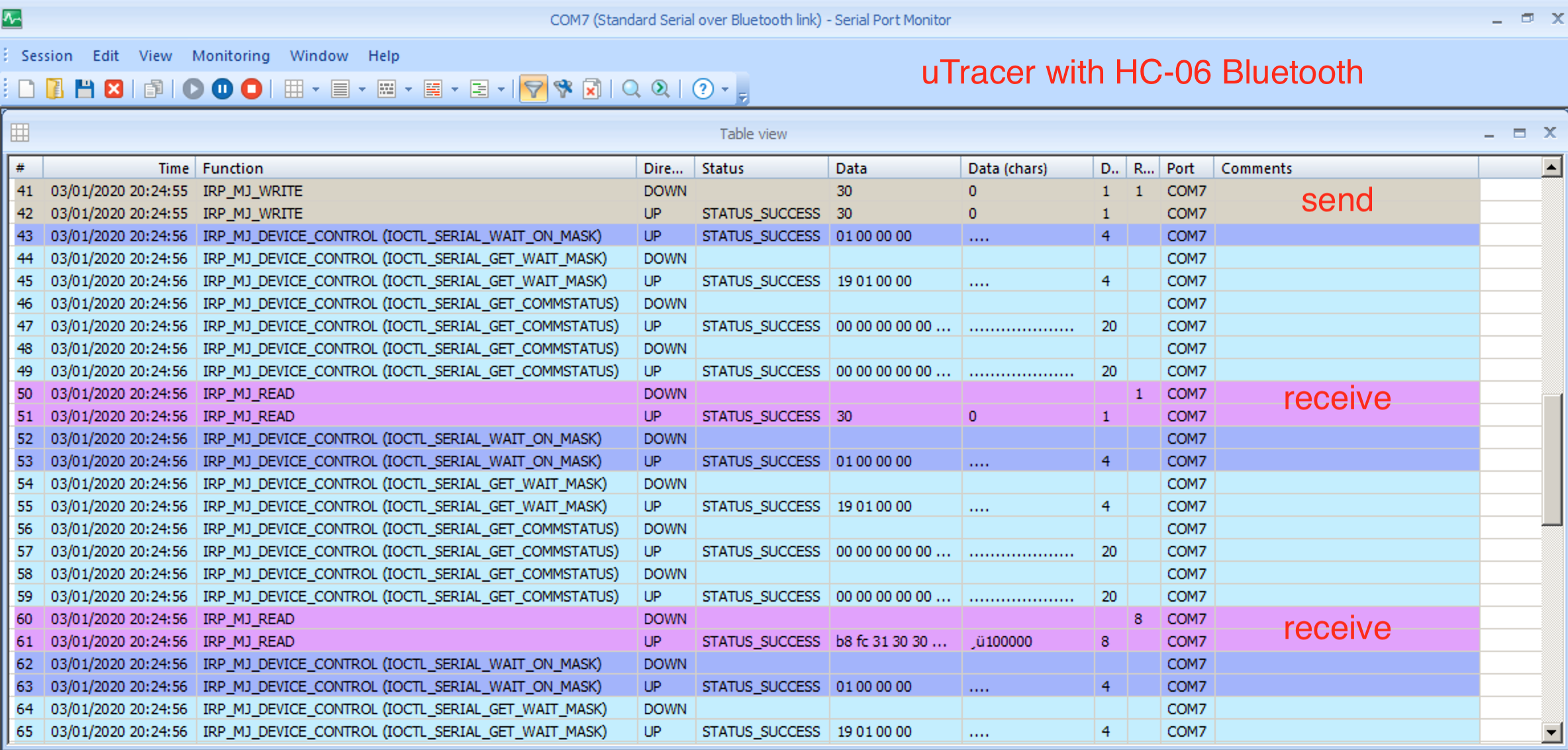
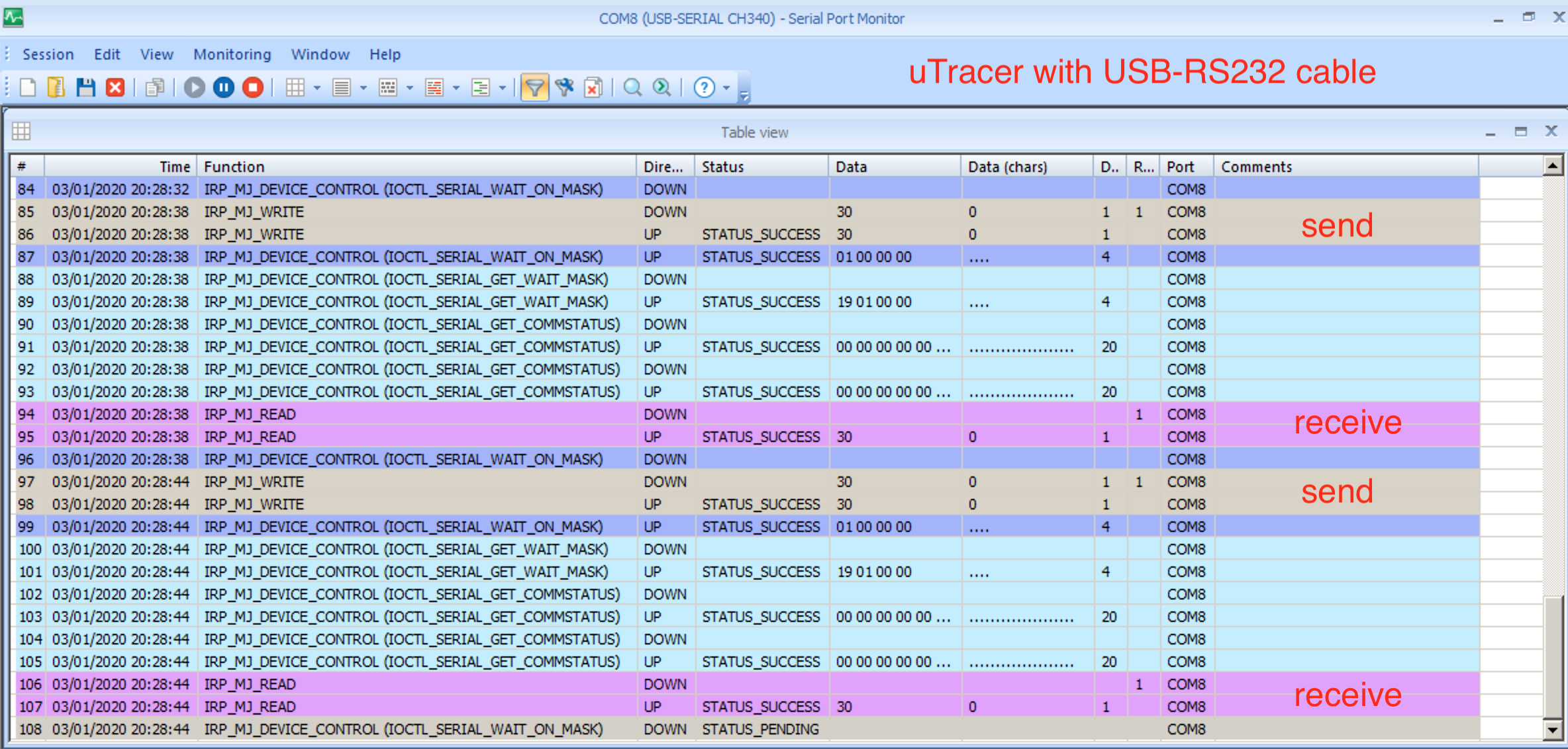
So you get the correct data from the HC-06 into the µTracer, and you get the proper response from the µTracer as long as its TxD is open. And as soon as you connect TxD to the HC-06 you get weird stuff coming out of the µTracer -- correct?
Is it possible that some kind of local echo is enabled for the HC-06? In that case is would echo back the bytes sent by µTracer, who would interpret this echo as another command and send an additional response, etc. I.e. does the data on the RxD line change when you connect TxD?
Ihor
Big Josh
--
You received this message because you are subscribed to the Google Groups "uTracer" group.
To unsubscribe from this group and stop receiving emails from it, send an email to utracer+u...@googlegroups.com.
To view this discussion on the web visit https://groups.google.com/d/msgid/utracer/eb6e1f96-6f3d-4c0f-b46e-045e9b038feb%40googlegroups.com.
Ihor
00000000008F08080850000000000000000000000000008F08080850000000000000000000000000008F400808500000000000000000100000000000000000000000FF0388000000FF40000000000000005210004600460045005210005C005C00990052100000000000000000000000FF0388000000FF10004800460045005210005C005C00990052100000000000000000000000FF0388000000FF10004300460045005210005C005C00990052100000000000000000000000FF0388000000FF10004600480045005210005C005C00990052100000000000000000000000FF0388000000FF10004600430045005210005C005C00990052100000000000000000000000FF0388000000FF1000460046004C005210005C005C00990052100000000000000000000000FF0388000000FF1000460046003E005210005C005C00990052100000000000000000000000FF0388000000FF3000000000000000005000000000000000000
or if you split it:
-the app initializes the utracer and wants to get some info from it
00000000008F08080850000000000000000000000000008F080808500000000000000000
-I am sending the wrong response and the app is happy and let me put the heater voltage
00000000008F400808500000000000000000100000000000000000000000FF0388000000FF
-the app puts the heater voltage:
400000000000000052
does not even check if it was successful or not
-the app runs the quick test for tubes:
100046004600450052
-I respond with the wrong echo and the measurements:
10005C005C00990052100000000000000000000000FF0388000000FF
-the app is happy with the wrong response and sends another response like that because the measurements are repeated a few times:
100048004600450052
-gets back again wrong echo
10005C005C00990052100000000000000000000000FF0388000000FF
and so on
100043004600450052
10005C005C00990052100000000000000000000000FF0388000000FF
100046004800450052
10005C005C00990052100000000000000000000000FF0388000000FF
So this is what I meant by quality: there is no error correction or detection implementation in that app. If some communication, as you mention, gets corrupted, the app can apply all the 450V and think that it is a measurement for 10V or so.
I see if I can dig into the problem with the real communication between the app and the uTracer through that HC-06 and will report what was wrong in my case.
To unsubscribe from this group and stop receiving emails from it, send an email to utr...@googlegroups.com.
Big Josh
To unsubscribe from this group and stop receiving emails from it, send an email to utracer+u...@googlegroups.com.
To view this discussion on the web visit https://groups.google.com/d/msgid/utracer/a9a4bc09-e566-4cc6-96b4-113e338f7607%40googlegroups.com.
Ihor
To view this discussion on the web visit https://groups.google.com/d/msgid/utracer/a9a4bc09-e566-4cc6-96b4-113e338f7607%40googlegroups.com.
Ihor
Big Josh
To unsubscribe from this group and stop receiving emails from it, send an email to utracer+u...@googlegroups.com.
To view this discussion on the web visit https://groups.google.com/d/msgid/utracer/a973cf11-76d6-47cc-bca4-bb27a5fbf4a8%40googlegroups.com.
Ihor
To view this discussion on the web visit https://groups.google.com/d/msgid/utracer/a973cf11-76d6-47cc-bca4-bb27a5fbf4a8%40googlegroups.com.
Big Josh
To unsubscribe from this group and stop receiving emails from it, send an email to utracer+u...@googlegroups.com.
To view this discussion on the web visit https://groups.google.com/d/msgid/utracer/4b4041f5-8dc7-41af-ba6a-8e2c44e7331a%40googlegroups.com.

BHdeC
To view this discussion on the web visit https://groups.google.com/d/msgid/utracer/4b4041f5-8dc7-41af-ba6a-8e2c44e7331a%40googlegroups.com.
nickb
Big Josh
To unsubscribe from this group and stop receiving emails from it, send an email to utracer+u...@googlegroups.com.
To view this discussion on the web visit https://groups.google.com/d/msgid/utracer/10e3c117-c859-41c8-8951-2340b96b49b8%40googlegroups.com.
nickb
To view this discussion on the web visit https://groups.google.com/d/msgid/utracer/10e3c117-c859-41c8-8951-2340b96b49b8%40googlegroups.com.
Ihor
BHdeC
Ihor
Unzip the downloaded uTmax.zip into your home directory i.e. /Users/YourName/. This will create a folder named uTmax_files.
In the folder utMax_files\uTmax_program_files, you will find the executable uTmax.exe. You can create a shortcut and add to your Start menu, if you wish.
Big Josh
To unsubscribe from this group and stop receiving emails from it, send an email to utracer+u...@googlegroups.com.
To view this discussion on the web visit https://groups.google.com/d/msgid/utracer/0a2d0c93-96df-432c-9ee9-f369e3310f52%40googlegroups.com.

nboba...@gmail.com
On Jan 16, 2020, at 10:47 AM, BHdeC <norman...@gmail.com> wrote:
--
You received this message because you are subscribed to the Google Groups "uTracer" group.
To unsubscribe from this group and stop receiving emails from it, send an email to utracer+u...@googlegroups.com.
To view this discussion on the web visit https://groups.google.com/d/msgid/utracer/17d38203-46e6-49dc-89c9-49827ee80e4a%40googlegroups.com.
nickb
To view this discussion on the web visit https://groups.google.com/d/msgid/utracer/0a2d0c93-96df-432c-9ee9-f369e3310f52%40googlegroups.com.
Big Josh
To view this discussion on the web visit https://groups.google.com/d/msgid/utracer/F16E5DA1-D781-4F33-88C2-187DF37FCE71%40gmail.com.
Ihor
Ihor

Walter Trovò
On Feb 19, 2025, at 7:49, Ihor <iste...@gmail.com> wrote:
Today I received some cheap bluetooth (BLE) modules (HM-10) for some other projects but I thought it might be interesting to try them with uTracer. Those are advertised as bluetooth-serial-port-capable but support only BLE (bluetooth low energy), which is is something "different" from the classical bluetooth. So typically desktops do not detect those modules as serail ports (compared to the modules that we discussed here 5 years ago). I tried one of the github projects that worked really nicely. I described the initial attempts here:
--
You received this message because you are subscribed to the Google Groups "uTracer" group.
To unsubscribe from this group and stop receiving emails from it, send an email to utracer+u...@googlegroups.com.
To view this discussion visit https://groups.google.com/d/msgid/utracer/5f2116f9-0749-4e5f-8945-a620bad383d4n%40googlegroups.com.
Ihor
Ihor

Davo
Op 19 feb 2025 om 22:36 heeft Ihor <iste...@gmail.com> het volgende geschreven:
For those who have a spare ESP32 and want to try to convert it into a serial bluetooth port I compiled the firmware from the project that I mentioned above. The instructions can be found at the bottom of this page https://boffin.nl/wp/utracerjs-bluetooth-ble-conenction/ See section "Bluetooth connection using ESP32"
--
You received this message because you are subscribed to the Google Groups "uTracer" group.
To unsubscribe from this group and stop receiving emails from it, send an email to utracer+u...@googlegroups.com.
To view this discussion visit https://groups.google.com/d/msgid/utracer/7ed78268-bc7d-49e2-a98c-c1bc4abbd114n%40googlegroups.com.
Ihor
Ihor
Ihor
Davo
Op 20 feb 2025 om 21:24 heeft Ihor <iste...@gmail.com> het volgende geschreven:
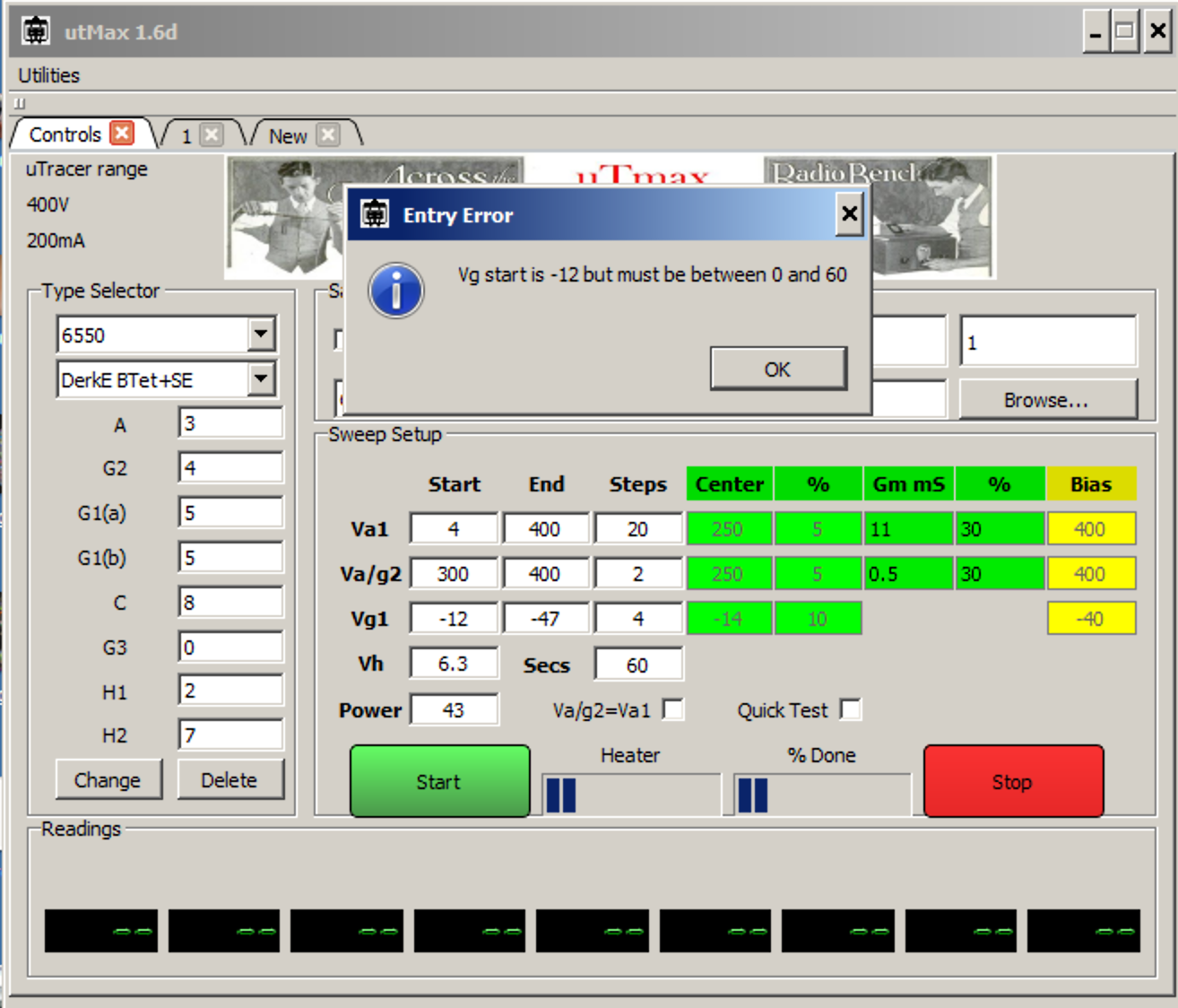
I implemented the support of the matrix board in uTracerJS and updated the version on the website. Here is a small screencast how to use it. As I do not have such board, it would be nice to know if it actually works. I would first start just with testing if there are clicks while setting up the pins, so if the communication works, and would wait a bit with running real tests, before I double check if the pin conversion from the file works good.In principle the problem with setting such boards (as I see from the description) is that there is no feedback or response message in the protocol that confirms that it was properly set, or even received the message, so with disruption in communication or errors one might think that the board is properly set and ready while it still has a configuration from the previous tube type, so the things can go terribly wrong if such test is executed.
--
You received this message because you are subscribed to the Google Groups "uTracer" group.
To unsubscribe from this group and stop receiving emails from it, send an email to utracer+u...@googlegroups.com.
To view this discussion visit https://groups.google.com/d/msgid/utracer/5f07b965-086e-49f6-a8bc-e1e33b671965n%40googlegroups.com.
Davo
Op 20 feb 2025 om 21:56 heeft Davo <djda...@gmail.com> het volgende geschreven:
Hi Ihor!

D.A.R Achterberg
Op 20 feb 2025 om 21:56 heeft Davo <djda...@gmail.com> het volgende geschreven:
Hi Ihor!
To view this discussion visit https://groups.google.com/d/msgid/utracer/B5D0D847-9521-4C21-8147-700F2F368AF2%40gmail.com.
Ihor
Davo
Op 20 feb 2025 om 22:42 heeft Ihor <iste...@gmail.com> het volgende geschreven:
I updated the version of uTracerJS, lets hope that this time it works, if not I will check Nick's example in python, how it is done there.
To view this discussion visit https://groups.google.com/d/msgid/utracer/78bea728-31e7-44d6-853d-13f522256e06n%40googlegroups.com.
Ihor
Davo
The example code, written in python is available online. So first I implemented just from the description, which is apparently not what it does. Now I ran that python code with an hardwave emulator of the matrix board and see that the 'message' is different. I updated the code of uTracerJS on the website, so it does exactly what python script does, but still it does not guarantee that that python example is actual and working and not a very early development version which is not valid anymore. If I find a windows machine next week I can also see what the latest version of utMax actually transmits.
--
You received this message because you are subscribed to the Google Groups "uTracer" group.
To unsubscribe from this group and stop receiving emails from it, send an email to utracer+u...@googlegroups.com.
To view this discussion visit https://groups.google.com/d/msgid/utracer/4c73dadd-480c-4ab6-a3db-305b10d39698n%40googlegroups.com.
D.A.R Achterberg
Op 21 feb 2025 om 01:02 heeft Davo <djda...@gmail.com> het volgende geschreven:
No magic happend…
To view this discussion visit https://groups.google.com/d/msgid/utracer/C6B84153-0A8B-4BAD-B6EC-8A02F8DEBED9%40gmail.com.