Thoughts on 40-pin long modules

Steve Cousins

Spencer Owen
--
You received this message because you are subscribed to the Google Groups "RC2014-Z80" group.
To unsubscribe from this group and stop receiving emails from it, send an email to rc2014-z80+...@googlegroups.com.
To post to this group, send email to rc201...@googlegroups.com.
To view this discussion on the web, visit https://groups.google.com/d/msgid/rc2014-z80/72714967-895d-4595-9bf9-87548fcc8dc1%40googlegroups.com.
For more options, visit https://groups.google.com/d/optout.

Mark T
Main driver for a 25mm height would be pcb cost. I use 102x100 panel for two 50x100 designs, separate the two with hacksaw between the modules where the connector hides the edge. This wouldn't work for 25mm height without a manual cut edge on the top of some cards. I guess it might work for 25x100 and 75x100 in a panel.
Mark
Steve Cousins

Peter Willard

Richard Lewis
Mark T
Mark T
Mark

Bill Shen
Bill

Phillip Stevens
The IDE interface pin out carries all of the signals buffered and registered required for cool things. Keyboards, printers, etc. See the 82c55 data sheet for hints.
I’d hope to build some things along this path soon. It would be great to be beaten to the first build.
Phillip

Marten Feldtmann
Steve Cousins
Steve Cousins
On Monday, 18 March 2019 08:40:55 UTC, Marten Feldtmann wrote:
Spencer Owen
--
You received this message because you are subscribed to the Google Groups "RC2014-Z80" group.
To unsubscribe from this group and stop receiving emails from it, send an email to rc2014-z80+...@googlegroups.com.
To post to this group, send email to rc201...@googlegroups.com.
To view this discussion on the web, visit https://groups.google.com/d/msgid/rc2014-z80/6fd4de74-8eea-48a5-abf0-91105325541a%40googlegroups.com.

karlab
Karl
Peter Willard

Tom Storey
On Monday, March 18, 2019 at 9:30:06 AM UTC, Steve Cousins wrote:
CTC to generate mode 2 interrupts for up to 8 non-Z80 devices
If I guesstimate correctly, you use one of the CTCs channels as a counter, triggered by the falling edge generated by the other devices interrupt pin. You load the counter with a value of 1, such that when the other device generates an interrupt, the counter decrements to 0 and the CTC then follows suit and provides a vector?

Alan Cox
actually easier in software in most cases because you get proper
interrupt masking features out of it trivially and you still have
plenty of bits left over even if you need several for the interrupt
lines.
You don't get a per interrupt vector for each of those devices but
it's one read to get the pending interrupts _and_ you can make it give
you interrupt prioritization behaviour which means you can take an
interrupt off the PIO and in the interrupt handler you can then change
the mode 3 control mask on the PIO to block that interrupt and reset
the pending interrupt, enable interrupts and carry on.
This allows you to do do proper priority driven interrupts where you
can interrupt and interrupt handler which the CTC one can't really do
well. Plus of course you get 16 unique interrupt sources per PIO if
you used a whole one rather than using the rest of it for joysticks,
SD card. MMU etc.
Steve Cousins
Alan Cox
>
> I've given quite a bit of thought to implementing look-ahead on the backplane or via flying leads and have not come up with a scheme I really like. If anyone has a good solution to this problem please post for discussion.
that supported IM2 like the Altos 5 and the Cromemco but even the S100
based Cromemcos used a seaerate chain of little cables for the IM2
stuff.
> Actually, the whole IEI/IEO chain on the backplane seems to spoil the simplicity of what I think a backplane should be. It is very nice to be able to put the modules in any slot you fancy and not worry about interrupt order, breaking the chain by leaving gaps, or using a module that doesn't link IEI to IEO. With enough dedicated pins you can solve these problems and even have look-ahead on a separate card. This method was mentioned recently by Tom Storey here: https://groups.google.com/d/msg/rc2014-z80/oGw1MAQXfn0/JQ89M6LiCAAJ
to an 8228 or similar and that generated multiple vectors in 8080
mode. If you had an 8085 you fed them to the multiple interrupt
vectors on the CPU. If you had a Z80 you could wire them to a PIO or
to any other logic you fancied to generate vectors or prioritize.
Other boards used whatever controller was appropriate for the CPU card
(8259 etc)
However it's 8 lines on the bus.
> 2 x SIOs giving 4 serial ports
> 1 x CTC to generate baud rates for some of the serial ports, plus provide tick interrupt*
> 2 x CTC to generate mode 2 interrupts for up to 8 non-Z80 devices
> 2 x PIO for anything else!
> So that's only 7 devices. Split across 3 modules, each with its own look-ahead, there is no need for additional off-card look-ahead.
down a CTC. You can fold the CTC, first SIO and first PIO into a KIO,
so that's down to 3 devices and you get some extra I/O lines in the
process.
I'm not sure I agree with you on the CTC being a bad timer for the
SIO. Nothing stops you using it to count external events off a
suitable crystal for the serial port clocks rather than internal time.
> There seems to be precious little software out there to make use of a proper Z80 mode 2 system. Trying to write such software when the hardware can be so diverse is quite possible, but not trivial. I've been considering making this part of SCM v2, with an API to install interrupt handlers for both mode 1 and mode 2 devices.
never found it much of a win or anything to get excited about. On the
other hand being able to do 8085 style prioritized interrupts is a
huge win IMHO.
IM2 is great for real time process control in an RTOS, but I don't
think anyone (despite Uncle Clive's advert) is planning to use RC2014
to control a nuclear power station 8)
Alan
Marten Feldtmann
Steve Cousins
Steve Cousins
suitable crystal for the serial port clocks rather than internal time. "
succeeding rising edge of Φ. As in the Counter mode, the triggering pulse is detected asynchronously and must have a minimum width. The timing
function is initiated in synchronization with Φ. A minimum setup time is required between the active edge of the CLK/TRG and the rising edge of Φ.
If the CLK/TRG edge occurs closer than this, the initiation of the timer function will be delayed one cycle of Φ.
Steve Cousins
Your solution has two Z80 I/O devices adding to your interrupt chain length. What are you doing about look-ahead?
Tom Storey
Alan Cox
classic IBM PC 1.843MHz crystal to generate the required baud rates at
x16. So you can go down to 4MHz happily. As you can drop to x64 mode
it's enough to get you all the bit rates you are likely to care about
unless you are doing 5bit baudot. (you can't quite get 110 baud).
(In fact you can go down to about 2MHz because you can then just use
the 1.843MHz clock for everything)
The other option if you have an RTC would be to time the CTC against
the RTC at boot and use that to compute the correct divider ranges.
I'd pondered doing that for the RC2014 Fuzix kernel and may do at some
point when an RTC is present.
Alan
Marten Feldtmann
Steve Cousins
Steve Cousins
Alan Cox
>
> Nothing really, I try to get rid of it by either:
>
> have a Z180 - use it's own SIO channels, own Timer for system tick, two CTC's for other interrupts and perhaps 1-2 PIO's
> have a Z80 - then I only consider to have ONE SIO, 2-3 CTC's and NO PIO.
onboard, you have the serial ports on board, you have the synchronous
serial to do SD card and most SPI devices at a nice speed.
Alan
Tom Storey
On Monday, March 18, 2019 at 12:58:23 PM UTC, Steve Cousins wrote:
I meant if you try to use a single CTC channel.
Mark T
For the IEI/IEO chain, the delay added by each Z80 peripheral is I think the limiting factor. This could be reduced by using an external AND gate to generate IEO from the IEI and the Z80 peripheral IEO.
I think the PIO, SIO and CTC were only available in 10 MHz, so it might be interesting to replicate them with CPLD some time.
I'd like to experiment with 16 bit data bus at some point so if I wanted extra pins on the bus I think I would use the higher address lines, A31..A24.
Mark
Steve Cousins
Steve
Tom Storey
On Monday, March 18, 2019 at 2:29:34 PM UTC, Steve Cousins wrote:
TomProbably just me not being clear.If two mode 1 style interrupt signals are connected to two CTC channels (on the same CTC or different CTCs) and they both request an interrupt at the same time, the CTC will generate two separate mode 2 interrupts, highest priority first. The handler for the highest will complete and then the lowest will fire. Same will happen if the lower priority one is requested during the handling of the higher priority one.If the lowest priority one occurs slightly before the higher priority one, the higher priority one can interrupt the lower priority one. So the handler for the lower priority one starts, then the higher priority one fires and its handler runs to completion, then the lower priority handler continues until completion.This mechanism is controlled by the IEI and IEO daisy chain, with a device under interrupt service lowering its IEO (output) which holds off lower priority devices (further down the chain) from issuing and acknowledging interrupts. The IEO signal ripples down the IEI/IEO chain, and must stabilise within a predetermined time. A long chain takes longer to stabilise than is allowed, and thus the discussion about look-ahead logic.
Steve
Marten Feldtmann
Marten Feldtmann
Marten Feldtmann

Tom Szolyga
Hi Alan,
Alan Cox
The N8VEM mark 4 is one that does this
https://www.retrobrewcomputers.org/doku.php?id=boards:sbc:z180_mark_iv:z180_mark_iv
The CSI synchronous serial on the Z180 can generate the right signals
for SPI except that
- It can't do full duplex
- It sends the bits in reverse order
- SD cards are 3.3v
(and of course you need a gpio or similar for chip select)
The full duplex turns out to be a non-issue. Almost no SPI device on
the planet actually *needs* full duplex. The bit reverse is done in
software. The SD card protocol above SPI is done in software. I've got
a CP/M implementation of the core SD protocol if you need it and
ROMWBW supports SD over the Z180 CSIO card fully.
There's a lot more to doing SD 'properly' but the simple SPI mode on
an SD card is more than good enough for 8bit micros.
Alan
Mark T
It might be best to avoid top edge on 75 or 100 mm high modules to avoid making the case too high.
Mark
Marten Feldtmann
Steve Cousins
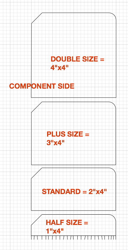
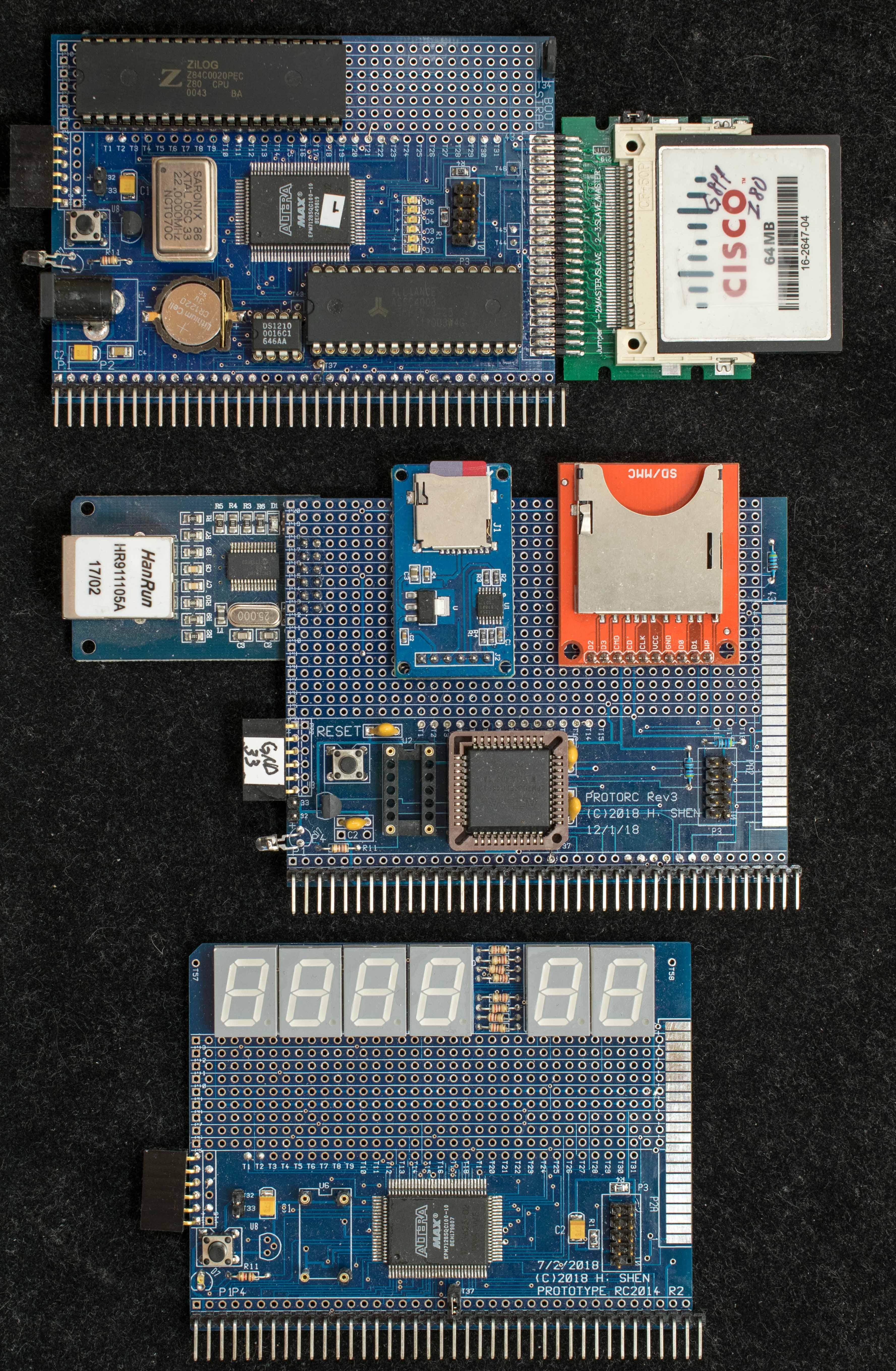
- Standard 50x100mm module extended for a 40-pin bus connector
- Plus size 75x100mm module
Spencer Owen
I propose we ask Spencer to give this his official approval as the suggested (or even recommended) way to support 40-pin bus connectors on a Standard'ish sized module.Perhaps the two variants of the Standard size module could be referred to as "Standard 39-pin" (or just "Standard") and "Standard 40-pin".
Steve Cousins
- Mark T - Card guide or PC style bracket
- Peter W - Pull handles
- Karl B - Case considerations
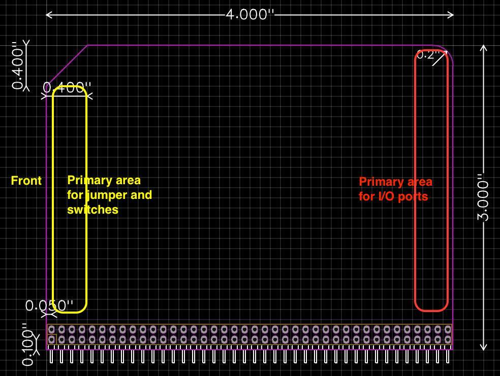
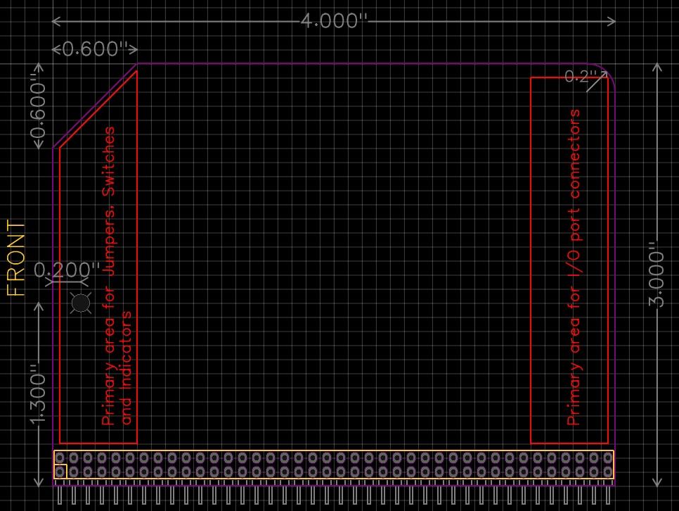
- Mark T - Suggest a standard position of I/O connectors from PCB edge
- Mark T - Top and front edges as secondary connector and indicator areas
karlab
Good work Steve
Marten Feldtmann
karlab
Marten Feldtmann

ZO...@gladucalled.com
On Sunday, March 17, 2019 at 6:36:50 AM UTC-4, Steve Cousins wrote:
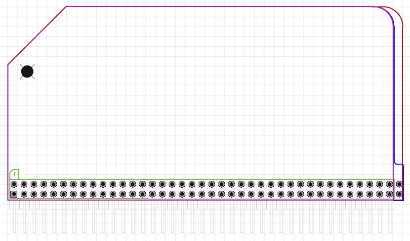
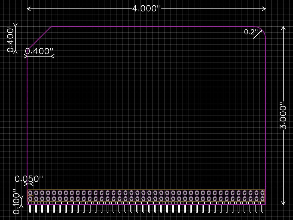
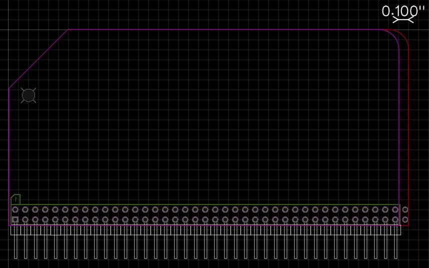
I would like to make modules that are 40-pins long, rather than the usual 39-pins.The attached illustration shows some possible board outlines.The RED outline shows a module which has simply been extended by 0.1". In a backplane with 39-pin modules this would stick out a bit and spoil the consistent look.o
oo