New backplane - wishes ?
1,259 views
Skip to first unread message

Marten Feldtmann
Jun 23, 2018, 2:41:10 AM6/23/18
to RC2014-Z80
If anyone is considering constructing a new backplane I would have wishes:
* A17, A18, A19 - to offer possible usage of Z180 and ez80 possibilities
* IE0, IEI and other missing Z80 signals
* double row connectors on the backplane (to get more stability)
* Power-On AUTO-RESET
* 3.3 and 1.8 v power supply (from 5V) ... (to get nearer to PI hardware)
:-)
Marten
* A17, A18, A19 - to offer possible usage of Z180 and ez80 possibilities
* IE0, IEI and other missing Z80 signals
* double row connectors on the backplane (to get more stability)
* Power-On AUTO-RESET
* 3.3 and 1.8 v power supply (from 5V) ... (to get nearer to PI hardware)
:-)
Marten

Steve Cousins
Jun 23, 2018, 4:13:51 AM6/23/18
to RC2014-Z80
Hi Marten
I'm working on a modular backplane which addresses some of your wishes.
I wanted an expandable backplane and one which could adapt to changing needs.
Two of the boards should be with me in a few days, the third is not yet ordered. Other modules planned.
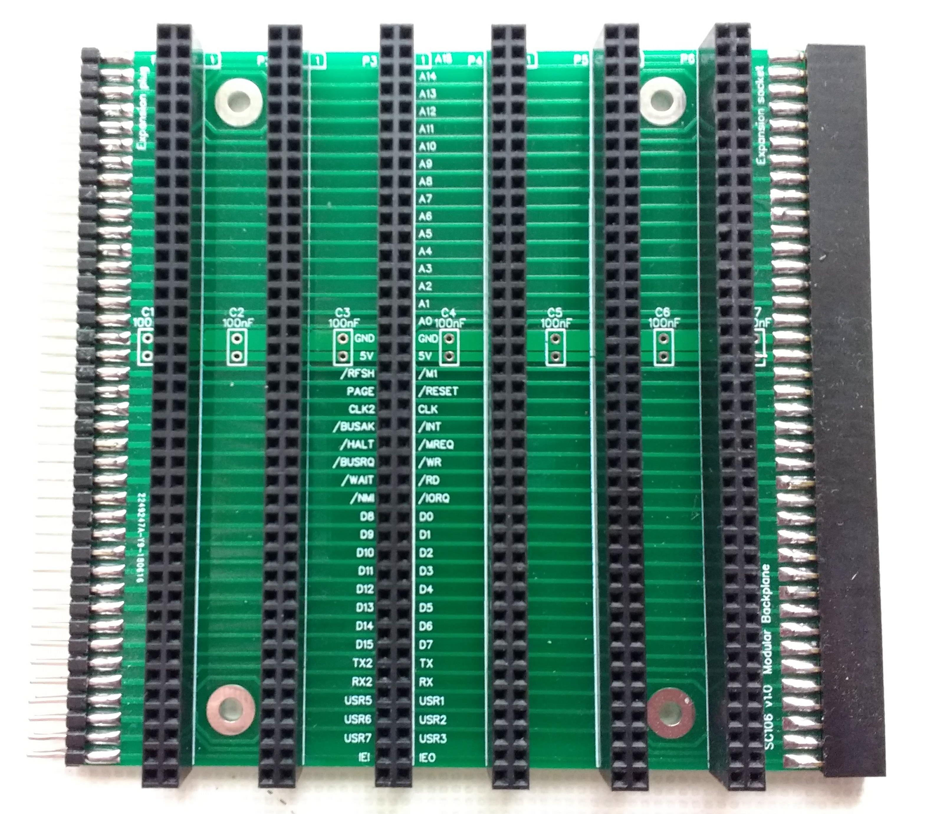
The first (SC105) has 6 RC2014 80-pin sockets and includes power input, power LED, reset button and ON/OFF switch. It has an 80-pin expansion socket edge mounted (80 pin header socket same as RC2014 slots).

With the current RC2014 module footprint pin 40 in both rows of the bus connector are not available due to the length of the PCB only being adequate for 39 pins. I have therefore hijacked these for IEI and IEO, thus providing support for mode 2 interrupts. But of course you need a larger footprint module to use them.
The next two backplane modules have an 80 pin RC2014 male header edge mounted on one end and an 80-pin socket edge mounted on the other. These can be used to extend the first board, each providing a further 6 slots each.
Backplanes SC106 is just a straight through bus extender with 6 RC2014 80 pin sockets. Straight through except IEO (pin 40) and IEI pin (80).
Backplane SC107 is similar to SC106, but duplicates IEI and IEO on USER2 (pin 38) and USER3 (pin 39). These match my CTC, PIO and SIO modules, and also the ZORAk Interocitor Motherboard.


So the idea is I make a backplane module to support whatever new innovation comes along in the RC2014 universe.
I'm also planning a board to connect to the LiNC Z50Bus. Similar to the above but the input end will have a Z50Bus connector. I may also make a backplane module with Z50Bus sockets, but RC2104 80-pin in and out connectors.
So to address your wish list.
A17, A18, A19 (and A16 I assume) - I think it is safe to say these can be allocated next to A0, A1, A2, etc. Perhaps Spencer could formalise this allocation.
IE0, IEI and other missing Z80 signals - IEI and IEO are taken care of in my design. Not sure what other Z80 signals you mean.
double row connectors on the backplane (to get more stability) - done
Power-On AUTO-RESET - I plan to put that on my CPU module (when I design it) along with the primary bus clock oscillator.
3.3 and 1.8 v power supply (from 5V) ... (to get nearer to PI hardware) - No solution or plans for these. I'm personally trying to stay 5 volt retro, but I guess I could add a backplane module with these voltages on some of the USER pins.
Comments anyone?
Steve

Eric Matecki
Jun 23, 2018, 6:12:36 AM6/23/18
to RC2014-Z80
That's an interesting concept...
I'm getting close to the limit of the Pro Backplane :)
Why not put the power/reset/etc... on a small board, and have only one kind of module with RC2014 connectors (or 2 with the SC107 variant).
This way, if someone wants a POR or 3.3V (say on one of the USRx lines), they just have to design a new small power board.
I, for instance, don't need/want a power switch, or even a power socket on my MB, just a screw terminal for power...
(That's not incompatible with the existence of the SC105 as a 'starter' module, just don't use them at the same time...)
The LiNC Z50bus 'connector' could also be a small module.
Another thing to check, will the spacing of the RC2014 sockets across modules be a multiple of the 'inner' spacing ?
That will make the manufacture of a case simpler.
Eric M.

Samster
Jun 23, 2018, 6:42:47 AM6/23/18
to RC2014-Z80
I think 3.3v would be useful as a lot modern peripheral chips and FPGA/CPLDs are 3.3v only, it would be good not to have to use module real estate to include a regulator or use up a slot. It could be an optional component on one of the USR lines?
Is there an easy to source 2x40 right angle male connector that can be soldered onto the modules a single piece (I've not checked)? I've been put off using the expanded bus so far because I end up melting the plastic on connectors if I spend too long trying to get them in the correct place.
Steve Cousins
Jun 23, 2018, 6:59:32 AM6/23/18
to RC2014-Z80
Hi Eric
Thanks for the feedback.
I did consider a power supply card (as opposed to backplane) but thought it was better to stick with the status quo on that one. As you say, the backplane does not prevent someone doing that, but it is worth noting that, as far as I know, no one has done it yet. Now, just waiting for all the "I have" comments!
I think a good compromise is to provide the standard power requirements on the backplane and the special USER# pin functions on cards. Thus I'd agree with your suggestion to put the additional low voltage source on a card.
I guess the whole question of where to put power connections, type of connector and use of ON/OFF switch comes down to personal choices and one hardware solution won't suit everyone. But that is also where a modular system is best - you don't have to change everything to get what you want.
My original 3 in the morning sketch for the modular backplane was for a small adapter board, but then I thought I might as well put some sockets on it and get better value from the PCB. My original sketches were carefully cut out and arrange on the desk to visualise the system :)
I did not design the system to have an equal spacing of RC2014 sockets across modules to spacing within a module, so I doubt that will work out.
Steve
Steve Cousins
Jun 23, 2018, 7:10:28 AM6/23/18
to RC2014-Z80
Hi Samster
Yes, 2x40 pin right angled male headers are easy to source. I get mine from eBay.
One eBay trader I've happily purchased from in the UK is BuyHere22:
Buying direct from China would save quite a bit when you want 20 or so.
However, 2x40 'pin' right angled female headers seem more difficult to find and rather expensive. This is why I went for the edge mounting of straight male and female headers.
This eBay trader mentioned above lists all the single and double row 40 pin variants, except the two row right angled socket.
Steve
Samster
Jun 23, 2018, 7:50:57 AM6/23/18
to RC2014-Z80
Good to know, I shall book mark the vendor page.
The other thing that I find useful on the backplane is quick access pins for logic analyzers. I found I ran out of slots on a small backplane to spare for debugging, but I guess here the edge connector would make a good non-permanent solution, like a 2x40 pin version of this:
Marten Feldtmann
Jun 23, 2018, 8:50:19 AM6/23/18
to RC2014-Z80
If I understand IEO and IEI correctly it gives the CPU-module a defined place in the first slot (slot(1)) of the motherboard ?
And IEO at slot x has to be connected to IEI at slot (x-1), what happens if one slot is not filled with a module ? In that case
must there be a switch to shorten the IEI (at slot x) with IEO (at slot x) ?
Is IEO at slot max(x) always tight to "1" ?
And IEO at slot x has to be connected to IEI at slot (x-1), what happens if one slot is not filled with a module ? In that case
must there be a switch to shorten the IEI (at slot x) with IEO (at slot x) ?
Is IEO at slot max(x) always tight to "1" ?
Steve Cousins
Jun 23, 2018, 9:35:49 AM6/23/18
to RC2014-Z80
Hi Marten
Actually IEI and IEO do not link to the CPU module so don't impose a position on it.
Yes, you are right about the chain between modules. Each mode 2 compliant device has an IEI and an IEO. The IEO of one module links to the IEI of the next. So, yes, if there is an unused slot between two mode 2 devices, that backplane socket needs to have a link between its IEI and IEO. I think a two pin male header with the ends joined would do the trick. I considered putting a jumper next to each socket, but decided a jumper shunt could easily get left in place when boards are moved around, while a link fitted in the socket would not. In any event it is likely that the relevant modules will be fitted in a tight group, so the need for a link will be minimal.
Regarding your comment about IEO being always high. I think you probably meant IEI. The first board in the chain has its IEI always high, indicating no higher priority device is present.
My SIO, PIO and CTC modules each have a pull up resistor on IEI, so there is no need to do anything special with the first board in the chain. The last board in the chain will have its IEO pin not connected to anything and will drive low when that module's interrupt is pending.
Steve
Eric Matecki
Jun 23, 2018, 9:41:59 AM6/23/18
to RC2014-Z80
Hi,
In fact, I wanted to say 'module', not 'board', for the power supply... oops :)
For 5V only a fullsize board will look like a desert :)
But, if you want also 3.3V (and maybe 1.8V), a board isn't a bad idea at all.
With jumpers to select on which of the USRx you want which voltage.
And maybe some optional features like POR, which you only populate if wanted.
Food for though :)
Marten Feldtmann
Jun 23, 2018, 11:12:32 AM6/23/18
to RC2014-Z80
Yes, you are right ... thanks for that explanation ...

Mark T
Jun 23, 2018, 12:13:03 PM6/23/18
to RC2014-Z80
I've taken a slightly different approach for a modular backplane where the backplane would be almost entirely passive. I include only a power led, to avoid unplugging from a powered system, and also because it was easy to fit. As its passive the first backplane would be identical to any additional extensions. Interconnection of pins 35 to 40 are only to adjacent cards unless linked on those cards or the backplane.
I found a set of right angled female headers on Amazon.
I used 102mm x 102mm as this allows 40 pin connectors and fits in the minimum cost for EasyEDA.
I've also laid out a memory board in 102x102 which would mount underneath the backplane, to allow 64K using 6264s, incorporating battery backup and an ADM694, for reset, write protect and power fail. This mounts 4 off 6264 on each side of the board so could be a bit of a mess to assemble. Also has memory management for Romwbw, with options for either flash rom or battery backed ram on the first chip and includes the memory management address lines to the second row of address pins to possibly expand to another card for 16 bit data.

karlab
Jun 25, 2018, 6:56:42 AM6/25/18
to RC2014-Z80
I have made several backplanes, but I am more in favor of simple backplanes.
E.g. there has become an inflation in reset buttons on the various modules.
I prefer the double row female headers, they are more stable and sit evenly on the board.
I found that inserting and removing modules from a single row header may result in broken solder connections.
I have incorporated double row headers in all my designs, and have named the last 8 slots X0 to X7 as in extra.
My series of tested and working BackPlanes see below;
It is possible to mount single row headers and later if necessary the second row of headers.
I am also a fan of smaller backplanes with fewer slots, my preferred setup is only using 4 modules.


Steve Cousins
Jun 25, 2018, 8:07:15 AM6/25/18
to RC2014-Z80
Hi Karl
That's quite a set of backplanes you have there.
Are they available anywhere for others to have made.
Steve
karlab
Jun 25, 2018, 3:50:41 PM6/25/18
to RC2014-Z80
Hi Steve
The primary purpose for the narrow backplanes (4,5,6) was to fit in a small blue box I have mentioned earlier,
and also have a spare room for a power supply, and maybe a disk drive.
The wider backplanes are very simple and robust design for general purpose, and I don't have many modules in my preferred setup so 6 slots are plenty for me.
I generally power my kits through the USB/FTDI cable.
I can make the designs available through easyEDA.
There is a similar product available at tindie.com, by Dtronixs, simple backplane with double row female header.
karl
Marten Feldtmann
Jul 15, 2018, 3:35:01 AM7/15/18
to RC2014-Z80
Have you any timestamp to publish this new backplane ? Perhaps with all changes (A16-A19 etc ...) and perhaps with name for the open 16 lines (just to make a possible standard for the future - actually its just a name on the board):
(4): A16, A17, A18, A19
(2): +3.3v , +1.8v (even though nothing has been build - but actually IF someone is building a module ... here it goes)
(2): SDA, SCL for potential I2C communication (for 3.3V level) (even though nothing has been build - but actually IF someone is building a module ... here it goes)
(8): USER-PINs
leaving 4 pin for additional usages.
Steve Cousins
Jul 15, 2018, 7:34:32 PM7/15/18
to RC2014-Z80
Hi Marten
I have a set of working modular backplanes, but I'm not sure I'm happy enough with the designs to 'publish' them. So no time scales yet.
As for allocating bus pins for the uses you listed, I think it would be best to get Spencer's input on that.
While any of us can do whatever we like with a 40 or 80 pin connector, we may sacrifice future compatibility if we use the currently unallocated RC2014 bus pins.
For what it is worth I think using A0 to A3's partner pins for A16 to A19 is a safe bet, but any other use of the A# pins is asking for future compatibility problems.
I do think it would be good to have I2C signals on the bus, but it might be better to generate any alternative power supply voltages on the modules that use them.
More user pins might be useful but I wonder if it would be sensible to isolate groups of sockets (as Mark T suggested, if memory serves) to get more uses from the limited number we already have. This is one of the things I'm considering for my modular backplanes, which is causing me to question my current designs. Actually Spencer has provided isolation points for some of the sockets on his backplanes. I think building on that mechanism is the way to get more functionality from a small number of user pins.
Steve

Bill Shen
Jul 15, 2018, 8:46:34 PM7/15/18
to RC2014-Z80
I particularly like the original RC2014 single-row bus because it can be plug into a solderless breadboard for experimentation. The trend is greater integration of components so ROM/RAM are now on the same board as CPU. With CPU/ROM/RAM on the same board, RC2014 bus becomes an I/O modules expansion bus so A8-A15 and MREQ signals can be reused for more sophisticated I/O applications. The overall system shrinks and becomes faster because of higher integration per board and fewer interconnects between boards.
Double rows of pins takes away precious board space and requires more room to route signals to these pins which make through-hole design in 50mm x 100mm pc board more challenging. I myself went to 1.5X form-factor (75mm x 100mm) and surface mount technology to squeeze in more features and free up slots on the backplane. However, I think most people find surface mount technology too difficult to work with. One reasonable solution is that boards with double rows are more stable, so it is possible to have 2X form-factor (100mm x 100mm) where the added board real estate offset the loss of space of extra row and signal routing.
These are my thoughts, I have no specific recommendations. I was slightly involved in a couple Standards Committee in my previous life, I do understand how difficult it is to establish a bus standard.
Bill
Marten Feldtmann
Jul 16, 2018, 3:05:51 AM7/16/18
to RC2014-Z80
Well yes - I have to rollback my opinion. This trend is viewable (CPU and RAM on one (perhaps larger) module) and actually this is a much better approach - so the additional address lines do not need to be put on the bus and the backplanes may evolve as an input/output bus.
And yes - I did the same thing with the single-row bus based modules ... very simple to stick them into a breadboard. On the other hand just connecting PIN 17 (GND), PIN 18 (+5V) on the extended bus still makes this possible - and it gives a much better (feelable) stability.
Marten
And yes - I did the same thing with the single-row bus based modules ... very simple to stick them into a breadboard. On the other hand just connecting PIN 17 (GND), PIN 18 (+5V) on the extended bus still makes this possible - and it gives a much better (feelable) stability.
Marten

Alan Cox
Jul 16, 2018, 6:08:26 AM7/16/18
to rc201...@googlegroups.com
On 16 July 2018 at 08:05, Marten Feldtmann <m.fel...@dimap.de> wrote:
> Well yes - I have to rollback my opinion. This trend is viewable (CPU and
> RAM on one (perhaps larger) module) and actually this is a much better
> approach - so the additional address lines do not need to be put on the bus
> and the backplanes may evolve as an input/output bus.
S100 and 80-bus both went to larger numbers of address lines (and also
> Well yes - I have to rollback my opinion. This trend is viewable (CPU and
> RAM on one (perhaps larger) module) and actually this is a much better
> approach - so the additional address lines do not need to be put on the bus
> and the backplanes may evolve as an input/output bus.
16bit data for S100, although the implementation requires much glue),
but both are from a time when 64K of RAM occupied a large board, and
when CPU speeds were low enough that the RAM could live on the end of
a long bus. The modern S100 boards for fast processors almost always
have the RAM on the board or a board next to it with a separate
connector.
The other option for physical stability of course would be to put a
second 40pin single in line bus on the top and agree a board height.
Then you can just use two backplanes ;-)
Has anyone looked over 80bus and S100 (and I guess ECB) to see which
lines were actually useful and worth having - like the S100 ability to
have multiple CPU cards and switch between them ?
Bill Shen
Jul 16, 2018, 1:03:53 PM7/16/18
to RC2014-Z80
Z280 seems well suited for multiprocessor configuration. Assuming the high order addresses can be reused, I think the original RC2014 single-row bus can be redefined to handle a small number of processors. a 8-slot backplane can probably accommodate a maximum of 4 processors. However, it is unclear to me what kind of applications can efficiently use such loosely-coupled multiprocessors configuration. Then again, I'm not much of a software person, so perhaps it is a case of "If you build it, they'll come"
Alan Cox
Jul 16, 2018, 4:10:11 PM7/16/18
to rc201...@googlegroups.com
> can be redefined to handle a small number of processors. a 8-slot backplane
> can probably accommodate a maximum of 4 processors. However, it is unclear
> to me what kind of applications can efficiently use such loosely-coupled
> multiprocessors configuration. Then again, I'm not much of a software
> person, so perhaps it is a case of "If you build it, they'll come"
The S100 arrangement wasn't multiprocessor but allowed multiple CPU
> can probably accommodate a maximum of 4 processors. However, it is unclear
> to me what kind of applications can efficiently use such loosely-coupled
> multiprocessors configuration. Then again, I'm not much of a software
> person, so perhaps it is a case of "If you build it, they'll come"
cards to share all the other expensive electronics and I/O devices
like those $500 floppy disk drives. There would be some kind of hand
off between the CPU cards so that one gave up being bus master and the
other took over.
It's more like you'd boot into say OS/9 or FLEX, then realize you
needed to use wordstar so could in effect type a command to reboot
into CP/M, then when
finished go back. It meant you could run multiple CPUs and systems
without having to keep changing cards or jumpers
There were also 'slave' processor cards - typically single board Z80
SBCs with their own RAM and serial I/O that had a messaging interface
on the shared bus so that you could run a master processor driving I/O
and maybe one user, while each other user got their own 'CPM in a
slot'. It was a way of getting lots of people sharing a mindnumbingly
expensive hard disk so not a usage case we have today.

ZO...@gladucalled.com
Jul 16, 2018, 9:59:21 PM7/16/18
to RC2014-Z80
Here's my two cents. I posted this before somewhere. As I said, it seems to me few people were using the TX, RX, and USER pins 1-4. So that is six free pins there.This is what I came up with for maximizing utility of a 40 pin connector. See pic below.It introduces IEI, IEO, and has a separate slot for a DMA card. As you look across backwards from right to left, you will see that these six pins come into RS2014 compliance as you walk down the board.In my design below, the IEI / IEO chain proceed right to left. With the chaining of slots, slot position becomes important. 3V3 is on pin 40 as an option for the last few slots. I think this will do everything I need. I also have Bus Links straps before the last two slots.I can run DMAI can daisy chain 5 interrupts.I have 3v3 on a few slots.I can break the TX, Rx, U1, and U2 links for multi-purposing.NMI is thrown in on one slot where I think I may need it.So, as I am not a fan of large pin counts, I ran with 40 pins. Large buses do not seem very vintage to me. Does anyone remember the STD bus with large goofy fingers - 32 of 'em? These were manly cards with edge connectors that you could spit on, rub it off on your shirt, an SLAM it back into the "card cage." These cards had balls that you could kick.The "bus" I show below is actually a motherboard w/ Z80, RAM, ROM, and Clock. Everything needs this so I put them put them on a backplane and made a motherboard. Still, I can strap out the memories, the clock, and the 3V3 and run standard RC2014 cards - which I plan to do to debug my backplane w/ know operational cards.BTW, on an SCC card I am making, there are straps on the card to let the chip run w/out IEI & IEO and IntAck. That way I can plug the card into a vanilla slot and use it that way. This raises an interesting idea.Maybe instead of new buses, there should be standards for the cards, such as a standard for interrupt chain cards, and DMA cards, and Serial Com cards, display cards, etc. For example, a interrupt chain configuration could be standardized which would also spec an "IEI/IEO" slot for cards that use chained interrupts. A spec for serial com cards could define how to bring out Tx and Rx and control signals - which User pins to use for control signals. To cover all possibilities, backplanes could be specified with breakable links between slots or configurable links. It would be a lot of work, but it would be nice to be able to use anybody's serial card or display card.(make that a Quarter - got carried away)Thanks for your thoughts, Bill. . . =Steve Markowski
Bill Shen
Jul 16, 2018, 10:57:10 PM7/16/18
to RC2014-Z80
Hmmm, small world, the ability to keep multiple processors installed and have one processor running is something I'm working. Similar idea, but different implementation on RC2014. What I want is an universal 8-bit uP development kit to bring up different processors on RC2014. The kit revolves around a CPLD prototype board where half of CPLD signals are connected to RC2014 bus and other half are configurable for the specific uP.
https://groups.google.com/forum/#!topic/rc2014-z80/6VjAF7D3tXE
In the CPLD is a simple serial port with DMA capability. At reset, the serial port generates a bus request to the uP so the processor bus is relinquished. The serial port then wait for data from the console. Each serial data received is DMA to RAM memory starting from location 0x0. When a pre-programmed number of data are received (currently it is 512 bytes), the CPLD releases the bus request and the processor boots. RC2014 has Rx/Tx defined on the bus, so multiple processor modules each with its own bootstrap serial port can hook up to the Rx/Tx pins. There are 3 spare signals next to the Rx/Tx signals that can select which processor module the serial stream is for.
The idea is to select the uP-under-development and load the specific boot code for it. If the boot is successful, it can continue to fetch more data from CF module. If boot failed, hopefully it will leave some diagnostic trails such that a second working processor can be serially boot-up and examine the remains.
I have the bootstrap serial port working and is working on developing a Z80 processor (reinventing the wheel yet again but with a different tool). I'm not using the common serial Rx/Tx pins on the backplane. Each uP-under-develpment has its own dedicated serial port, but that can easily be consolidated into a common port.
With battery-backed RAM and a serial bootstrap module running at 115K baud, I'm of the opinion that ROM is entirely unnecessary. System code development is SO much easier if we don't have to deal with the hassle of ROM programming.
Bill
Mark T
Jul 17, 2018, 12:17:54 AM7/17/18
to RC2014-Z80
Does anyone remember the STD bus with large goofy fingers - 32 of 'em? These were manly cards with edge connectors that you could spit on, rub it off on your shirt, an SLAM it back into the "card cage." These cards had balls that you could kick.
My memory of card edge connectors is slightly different. Not that you could but More a case that you had to unplug the card, clean the connectors, replace the card at least once every day just to keep the system running. OK if you only had one, but we had about 50 of these to keep running in a factory environment. Big deal when 2764's became available and we replaced 4 memory cards with a single card to give big improvements in reliability.

Spencer Owen
Jul 17, 2018, 5:38:47 AM7/17/18
to rc201...@googlegroups.com
I've been musing over enhancements to the backplane for a little while now, and whilst nothing is set in stone, the pin layout would follow this;
| Enhanced | Standard | ||
| A31 | 1 | 1 | A15 |
| A30 | 2 | 2 | A14 |
| A29 | 3 | 3 | A13 |
| A28 | 4 | 4 | A12 |
| A27 | 5 | 5 | A11 |
| A26 | 6 | 6 | A10 |
| A25 | 7 | 7 | A9 |
| A24 | 8 | 8 | A8 |
| A23 | 9 | 9 | A7 |
| A22 | 10 | 10 | A6 |
| A21 | 11 | 11 | A5 |
| A20 | 12 | 12 | A4 |
| A19 | 13 | 13 | A3 |
| A18 | 14 | 14 | A2 |
| A17 | 15 | 15 | A1 |
| A16 | 16 | 16 | A0 |
| Gnd | 17 | 17 | Gnd |
| 5v | 18 | 18 | 5v |
| RFSH | 19 | 19 | M1 |
| Page | 20 | 20 | Reset |
| Clock2 | 21 | 21 | Clock |
| BUSACK | 22 | 22 | INT |
| HALT | 23 | 23 | MREQ |
| BUSRQ | 24 | 24 | WR |
| WAIT | 25 | 25 | RD |
| NMI | 26 | 26 | IORQ |
| D8 | 27 | 27 | D0 |
| D9 | 28 | 28 | D1 |
| D10 | 29 | 29 | D2 |
| D11 | 30 | 30 | D3 |
| D12 | 31 | 31 | D4 |
| D13 | 32 | 32 | D5 |
| D14 | 33 | 33 | D6 |
| D15 | 34 | 34 | D7 |
| Tx2 | 35 | 35 | Tx |
| Rx2 | 36 | 36 | Rx |
| USR5 | 37 | 37 | USR1 |
| I2C SDA | 38 | 38 | IEI |
| I2C SCL | 39 | 39 | IEO |
| USR8 | 40 | 40 | USR4 |
A few thoughts on the subject, in no particular order;
- The trickiest part for me releasing a new backplane would be the naming convention. What would be more superior to Backplane Pro? Backplane Pro Plus? Backplane Super Enhanced?
- The only power supply is 5v. If modules have devices that run at 3v3 or other voltages, then this should be done locally on the module.
- I2C logic levels will probably be 3v3 - however, they could easily be 5v depending which device you use (Atmel ATMEGA328 uses 5v I2C, for example). If you use an I2C chip on your module that isn't 5v tolerant, you should do local level shifting.
- Tx and Rx are used by a lot of people. There are several hundred Pi Zero Terminal Modules out there that use Tx and Rx, as well as almost 100 ESP modules that use both Tx, Rx and Tx2, Rx2. I would strongly advise against using these pins for anything else.
- Bus isolation, as used on the Backplane 8 and Backplane Pro does allow for partial segregation of the signals, so grouping some boards on either side of the segregation does allow for different uses of the pins. Both the Backplane 8 and Backplane Pro only do this for the standard bus, and this is likely to be the same for Backplane Super Dooper too.
- The Old McDonald signals (IEI, IEO) would only have a limited range on the backplane. Probably 3 or 4 slots, which should be plenty for the amount of potential modules that would take advantage of that. Outside of these slots, it would be safe enough to use pins 38 and 39 for USR2 and USR3.
- There is no specific support for running multiple different CPUs concurrently. This really goes way beyond what RC2014 is aimed at.
- Although there does seem to be a trend towards having multiple functions on a single module, this goes against the simple bus ethos that the RC2014 was built upon. Although I made the 512k ROM 512k RAM Module on a single board, I would have been much happier if it had been split over 2 different boards. For that design, though, the ROM and RAM were so integrated that it was the sensible option to put them on one board. However, I really prefer that every general function be on its own module, as that will give the greatest flexibility in the long run. Having the CPU and clock on the same module might seem to make sense, for example, but if you want to upgrade to a new CPU module, you've got to either get a separate clock module anyway or integrate the clock on the new CPU module
I hope that helps, and gives you something to work around. When I get back to the office next week, I'll update https://rc2014.co.uk/1377/module-template/ with this info.
Spencer
On 17 July 2018 at 05:17, Mark T <mark...@gmail.com> wrote:
Does anyone remember the STD bus with large goofy fingers - 32 of 'em? These were manly cards with edge connectors that you could spit on, rub it off on your shirt, an SLAM it back into the "card cage." These cards had balls that you could kick.My memory of card edge connectors is slightly different. Not that you could but More a case that you had to unplug the card, clean the connectors, replace the card at least once every day just to keep the system running. OK if you only had one, but we had about 50 of these to keep running in a factory environment. Big deal when 2764's became available and we replaced 4 memory cards with a single card to give big improvements in reliability.
--
You received this message because you are subscribed to the Google Groups "RC2014-Z80" group.
To unsubscribe from this group and stop receiving emails from it, send an email to rc2014-z80+unsubscribe@googlegroups.com.
To post to this group, send email to rc201...@googlegroups.com.
To view this discussion on the web, visit https://groups.google.com/d/msgid/rc2014-z80/284759e9-be18-4767-ba68-b9ffb87b8782%40googlegroups.com.

Ralph Hyre
Jul 17, 2018, 5:43:39 AM7/17/18
to RC2014-Z80
I’d love to see the IEEE Standard STEbus (IEEE-10000) make a comeback. It has a Wikipedia page.
It used 64 pins of the P2 connector on a VME backplane.
As long as a different connector style was used, it could
Be adapted to a different connector type, at the expense of compatibility. it was CPU-agnostic.
A DSKY (display/kbd) board or LED switch / front panel board would be obvious peripherals to share..
Alan Cox
Jul 17, 2018, 7:12:01 AM7/17/18
to rc201...@googlegroups.com
I'm not sure A24-A31 are that useful. By the time you get to 32
address lines you are into the territory of 68020 / 386DX and need a
32bit data bus and your processors run too fast for that kind of
backplane to carry memory.
68000/010 is 24bit address 16bit data
386SX is 24/16
Rabbit is 24/8 (with a demented chip select regime)
Z280 is 24/16
65C816 is 24/8
68HC11K goes up to about 24/8 if I remember rightly
NS32016 is 24/16
Also if you go to 16bit data you have to decide how the CPU card knows
if the thing being accessed is 8 or 16bit wide, and specify what A0
means in that case.
In other words with a 16bit wide RAM card is
address 0 16bits
address 1 the next 16bits
or
address 0 16bits
address 1 invalid
address 2 16bits
or
is it simply byte addressed
How to does it work for peripherals - what happens if you have a RAM
card you want to use for both 8 and 16bit CPU. S100 solved this but
the solution was horrible 8)
ISA bus has logic so the card signals the system board, but that
caused a whole world of pain because the timings are very tight as it
has to respond to the address on the bus and tell the motherboard
'hold on I'm 16bit' before the next part of the bus cycle.
Looking at all the modern microcontroller boards I suspect it might be
more interesting to use some of those for
3v3
MISO
MOSI
SPICLK
Say 3 bit SPI selection (giving 7 devices + off)
so that it's possible to plug in a CPU<->SPI card and then use all
sorts of off the shelf SPI components, SD card etc.
Or maybe it would actually be more sensible to have such a card
provide a cable link to a second SPI backplane instead.
Comparing it with NASBUS/80-bus is quite interesting. Even down to
both having a signal for paging out stuff.
The original NASBUS provides the following that your proposal doesn't
DBDR - data bus direction. Not clear it's useful.
-12v/-5v/+12v. Kind of obsolete (and no board shall draw more than
1amp 12v and 2amp 5v .... 8))
but it actually looks like you could trivially build a NASBUS/RC2014 convertor
80BUS extended it and added
A16-A18 (and everyone added A19 on a spare line)
INT0-INT3 (the original just has the IEI/IEO chain)
PWRF (power about to fail)
AUX PWR (auxilliary power)
So compared with 80-bus the only real differences seem to be power
related and the board having four interrupt lines
S100 is a bit fancier (and a lot more glue)
The main (no historical quirk) thing S100 has is a clear concept of
bus masters for DMA. So there are DMA request lines, and a clear model
of how a card forces the main processor off the bus. It also has a
power good signal generated from the power/backplane side of things so
everything knows when the power is ok. It's also tied in with reset
and slave clear.
Otherwise
All sorts of voltages and grounds
Has VI0-VI7 for vectored interrupts
Several pins for the front panel including a single step line
Data in/out is split into two different sets of 8pins (or 16bit
bidirectional later)
S100 also never went over 24bit address / 16bit data
I think there is one lesson maybe from S100 though. S100 had no stable
general 5v signal across the bus, so every card ended up doing power
which meant a lot more heat and regulators. 5v to 3.3v is easier but
it makes me wonder if there shouldn't be an optional 3.3v signal on
the bus.
As for names - Backplane Duo, Backplane16 ?
Marten Feldtmann
Jul 17, 2018, 9:12:05 AM7/17/18
to RC2014-Z80
eZ80 is also 24/8 ...
And yes 24 Bts allows 16 MByte of RAM ... this should be more than enough
for lots of retro stuff ...
Marten
And yes 24 Bts allows 16 MByte of RAM ... this should be more than enough
for lots of retro stuff ...
Marten
Mark T
Jul 17, 2018, 9:46:46 AM7/17/18
to RC2014-Z80
Maybe the ECB of N8VEM could also be considered if you wanted a bus for a larger system, there are a few board designs available for different processors.
I think the real value of RC2014 is that it aims at a lower complexity on the bus interface, avoiding much of the glue logic and buffering of S100 etc. This allows the pcb size to be reduced and makes it significantly cheaper for experimental boards.
I've had some thoughts on building an RC2014 motherboard that would fit into my older microtan 65 system, possibly with a tube type interface on the motherboard with maybe 6 or 7 slots. Card size in this system was 203mm x 115mm, so could accomodate 40 pin bus connections and still slide into the rack.
This approach might also work on S100, but for ECB would probably require a move to double eurocard or a reduced number of RC2014 slots across the width of the eurocard, probably not enough slots to be usefull.
An alternate to a 32 bit address bus may be to split the memory and IO address bus to support flyby DMA. Most RC2014 cards are IO, so current A0 to A7 would be the IO address bus, memory address A0 to A7 and A16 to A23 would be on the enhanced bus.
Mark T
Jul 17, 2018, 10:03:38 AM7/17/18
to RC2014-Z80
For SPI on RC2014 it might make more sense to have a separate BUS. I was looking on Tindie at the modules by Explore Labs and it looks like a 9 pin bus could support most SPI modules. Perhaps a single RC2014 card with an SPI interface and 8 x 9 pin headers as a bus with two CS decoded for each slot.
Are there any existing SPI bus designs that would be a defacto standard to follow?
ZO...@gladucalled.com
Jul 17, 2018, 10:06:01 AM7/17/18
to RC2014-Z80
Hi Bill,
Bill,
I found a Z80 FAQ sheet that answers a question about how to test devices and buses on a Z80 computer without having to take out the Z80. Zilog said you can just remove power from the Z80 and leave all the other pins connected. It will not interfere with the signals on the other pins. So if I understand this correctly, one could have a bunch of Z80s on the same bus with independent power controls on the same bus.
May this work with any NMOS or CMOS part?
You have a very interesting design. I think it will handle anything you want to try. I like the separate Tx Rx pins for each slot (as I understand what you are saying).
See a clip from the Zilog FAQ below.
Has anyone tried two processors on the bus w/ disconnecting Vcc and ground on one of the CPUs? Seems crazy, but maybe it works.
=Steve.
Message has been deleted
Bill Shen
Jul 17, 2018, 12:13:00 PM7/17/18
to RC2014-Z80
Steve,
Removing power AND ground should isolate the device but it is much easier to just drive BUSREQ to tristate signals which is what I did. For most uP driving BUSREQ should tristate address/data/control signals.
Bill
Removing power AND ground should isolate the device but it is much easier to just drive BUSREQ to tristate signals which is what I did. For most uP driving BUSREQ should tristate address/data/control signals.
Bill
Alan Cox
Jul 17, 2018, 12:18:21 PM7/17/18
to rc201...@googlegroups.com
6 pins in incompatible ways for different stuff (and it's trademarked
so has rules). In some ways it's the most RC2014 like as it's just six
pins.
UEXT is another with a lot of modules that is only 3.3v but does
specify pins for serial/i2c/spi. It's also dirt cheap (an off the
shelf 5 slot backplane from Olimex
is £2). It's in theory vendor owned but Olimex just say 'please use it'
I believe there's another one that some of the FPGA boards use as a
standard module ?
Alan
ZORAk
Jul 17, 2018, 4:21:23 PM7/17/18
to rc201...@googlegroups.com
Hi Spenser,
I do think you should allow for 3V3 somewhere, maybe as an option. Although a small T0-92 regulator and two caps provide a supply from five volts.
Like seeing the I2C accounted for. Love the IEI / IEO addition.
What does Page do? Is this a memory control of some sort?
=Steve.
You received this message because you are subscribed to a topic in the Google Groups "RC2014-Z80" group.
To unsubscribe from this topic, visit https://groups.google.com/d/topic/rc2014-z80/oGw1MAQXfn0/unsubscribe.
To unsubscribe from this group and all its topics, send an email to rc2014-z80+...@googlegroups.com.
To post to this group, send email to rc201...@googlegroups.com.
To view this discussion on the web, visit https://groups.google.com/d/msgid/rc2014-z80/CAO93Ptdd0SrWQsepiJGkwoLqyM_cjLNy%2Bi%2BwNSLWp0bRVMaWsg%40mail.gmail.com.

Andrew Quinn
Jul 21, 2018, 3:19:58 AM7/21/18
to RC2014-Z80
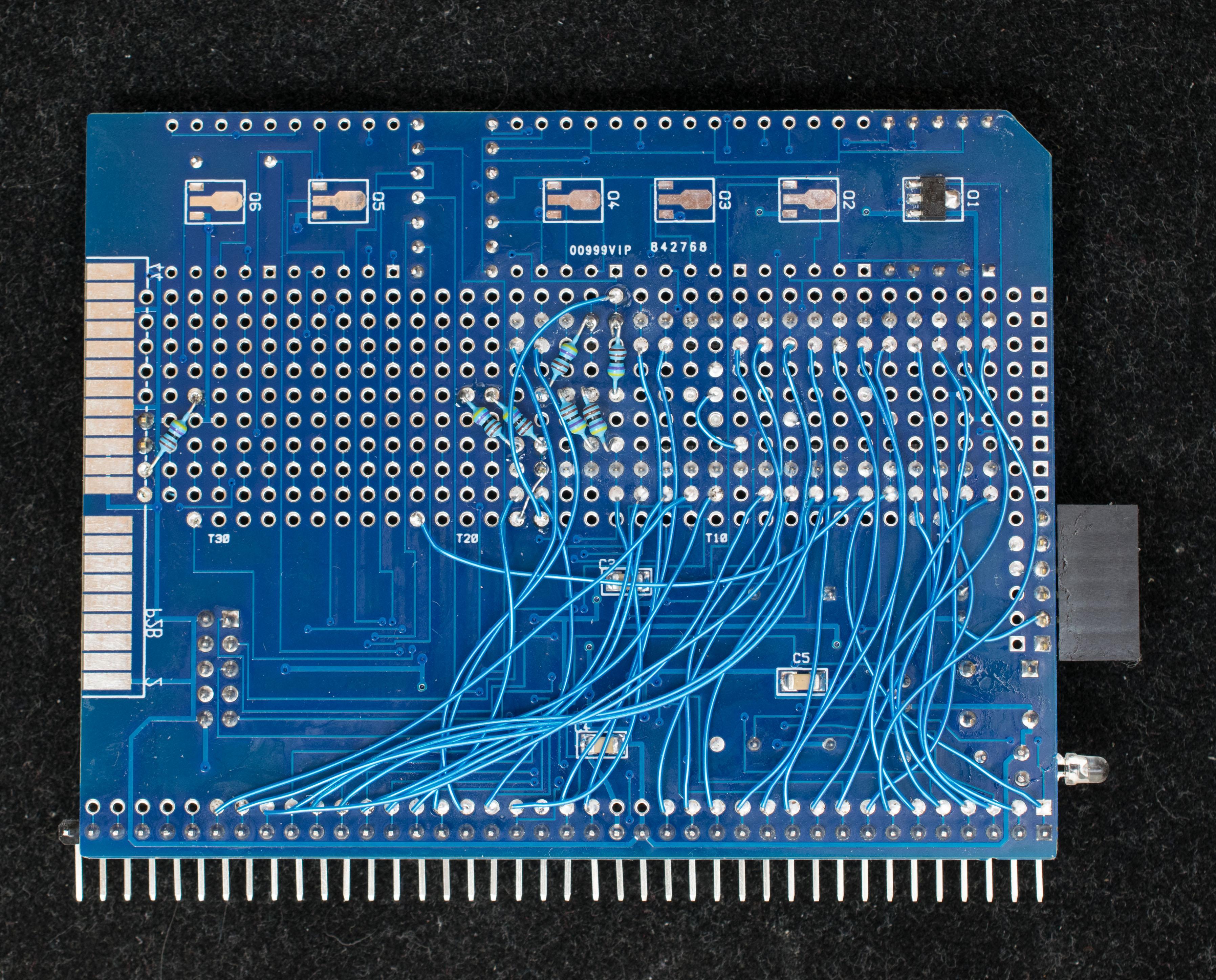
I used a similar layout on my mainboard but it was really based on what Zuzebox and DTronixs had already published.

The resistors on some lines are actually SMD resistor pads on the mainboard which can be jumpered to connect the uncommitted bus lines or left open to break into segments.

Above is an assembled board populated with Scott Baker RAM/ROM, SIO, CPU and Single Stepping board. The power supply is a switching regulator rather than a 7805. The board includes a RESET circuit that can be disconnected from the /RESET line with a jumper if not required for the board set in use.
Nothing revolutionary but it has been fun.
ZORAk
Jul 21, 2018, 9:22:02 AM7/21/18
to rc201...@googlegroups.com
Looks good, lots of spares.
--
You received this message because you are subscribed to a topic in the Google Groups "RC2014-Z80" group.
To unsubscribe from this topic, visit https://groups.google.com/d/topic/rc2014-z80/oGw1MAQXfn0/unsubscribe.
To unsubscribe from this group and all its topics, send an email to rc2014-z80+...@googlegroups.com.
To post to this group, send email to rc201...@googlegroups.com.
To view this discussion on the web, visit https://groups.google.com/d/msgid/rc2014-z80/6a176ebf-6751-43db-beb1-38aa3b077795%40googlegroups.com.
Marten Feldtmann
Aug 11, 2018, 4:59:12 AM8/11/18
to RC2014-Z80
Hello,
can you tell me, how you created these expansion bus in easyeda ? I would like to try that out - but with different physical values (width, number of connectors). I assume, that these connectors are also on the botton side of this layout ? for my old computer I need a 2x22 pin connectors. I am considering creating an adapter to use RC2014 modules in my old Sharp MZ-80B computer - or at least to try that idea out.
Thanks,
Marten
Am Samstag, 23. Juni 2018 10:13:51 UTC+2 schrieb Steve Cousins:
It has an 80-pin expansion socket edge mounted (80 pin header socket same as RC2014 slots).
I'm also planning a board to connect to the LiNC Z50Bus. Similar to the above but the input end will have a Z50Bus connector. I may also make a backplane module with Z50Bus sockets, but RC2104 80-pin in and out connectors.So to address your wish list.A17, A18, A19 (and A16 I assume) - I think it is safe to say these can be allocated next to A0, A1, A2, etc. Perhaps Spencer could formalise this allocation.IE0, IEI and other missing Z80 signals - IEI and IEO are taken care of in my design. Not sure what other Z80 signals you mean.double row connectors on the backplane (to get more stability) - done
Power-On AUTO-RESET - I plan to put that on my CPU module (when I design it) along with the primary bus clock oscillator.
3.3 and 1.8 v power supply (from 5V) ... (to get nearer to PI hardware) - No solution or plans for these. I'm personally trying to stay 5 volt retro, but I guess I could add a backplane module with these voltages on some of the USER pins.Comments anyone?Steve
On Saturday, 23 June 2018 07:41:10 UTC+1, Marten Feldtmann wrote:If anyone is considering constructing a new backplane I would have wishes:
* A17, A18, A19 - to offer possible usage of Z180 and ez80 possibilities
* IE0, IEI and other missing Z80 signals
* double row connectors on the backplane (to get more stability)
* Power-On AUTO-RESET
* 3.3 and 1.8 v power supply (from 5V) ... (to get nearer to PI hardware)
:-)
Marten
Steve Cousins
Aug 12, 2018, 7:15:12 AM8/12/18
to RC2014-Z80
Hi Marten
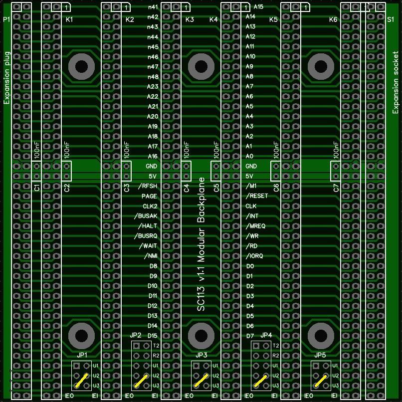
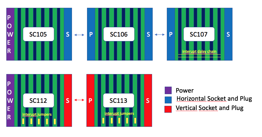
I've made the backplane project (SC105) and an alternative design (SC112) shared at EasyEDA.
You can go to EasyEDA.com and search for "sccousins" or "SC105" or "SC112". Or you can search "RC2014" to find other RC2014 projects.
You will then be able to view and edit a copy of the designs in EasyEDA's browser based editor. It takes a while to get the hang of any PCB design software, but it is worth the effort.
I'd recommend using SC112 as this has a better schematic and is generally a later and better design. The main difference between the two is that SC105 uses an edge mounted expansion socket while SC112 uses a through hole socket. SC112 also has jumpers for USER 1 to USER 3 to isolated or connect between sockets.
I've yet to make shared the extension sections SC106, 107 and 113.
I too see the modular design as a way of incorporating different connection systems and make adapters. I have started a backplane section for the LiNC80 Z50Bus, but haven't finished it yet!
To answer your question, yes, the 'finger' pads are also on the bottom to allow a two row socket to be fitted with all 80 signals supported.
To get the best out of EasyEDA's software you should create a schematic and then 'convert to PCB' or 'update PCB'. You can then edit the schematic and update the PCB without having to start again. There is an autoroute feature, but I prefer manual routing.
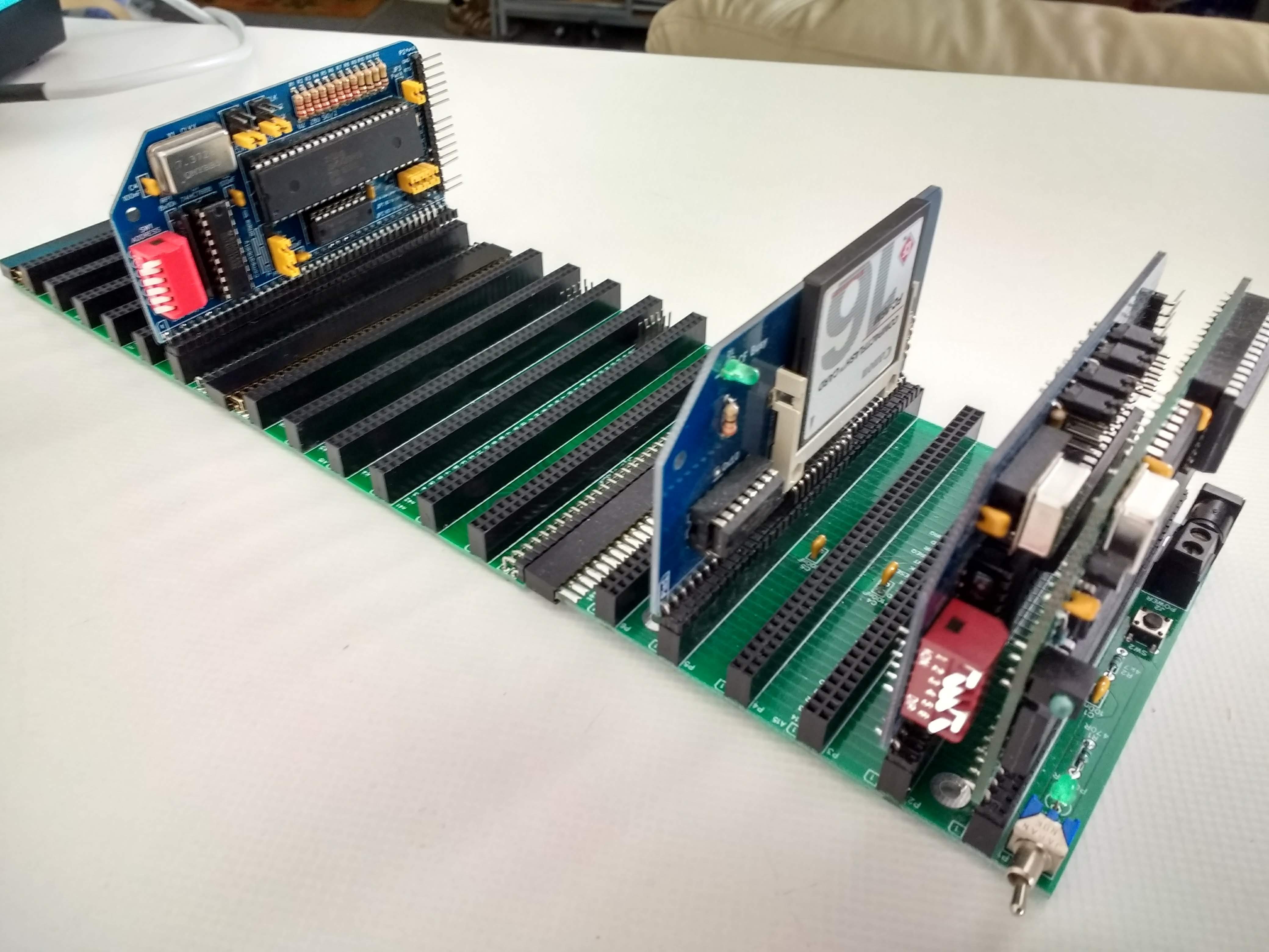
The photo below shows backplane SC105 connected to SC113 expansion sections. Note SC105 has an edge mounted connector while the SC113 expansion section has a through hole connector.
Steve


Conrad Larsen
Aug 14, 2018, 8:16:26 AM8/14/18
to RC2014-Z80
Hi Steve
Your backplane SC112 is very cool.
Conrad

G Kr
Aug 14, 2018, 10:12:58 AM8/14/18
to RC2014-Z80
Hi Steve,
Very good work, as far as I can tell...
You write that you have shared the extension sections SC106, 107 and 113.. But where can I get the SC113?
I can not see it on https://easyeda.com/.
I can not see it on https://easyeda.com/.
Can you help me. I would like to order some of them.
Gerd
Steve Cousins
Aug 14, 2018, 10:17:05 AM8/14/18
to RC2014-Z80
Hi Gerd
Perhaps what I wrote was badly worded: "I've yet to make shared the extension sections SC106, 107 and 113."
I will share these soon on EasyEDA, I just need to add descriptions etc.
I'll post here when I have done so.
Steve
G Kr
Aug 14, 2018, 10:35:25 AM8/14/18
to RC2014-Z80
Oh, sorry, I did not want to jostle. :)
Gerd
Steve Cousins
Aug 21, 2018, 4:10:01 PM8/21/18
to RC2014-Z80
Hi all
I've made all my modular backplane designs public at EasyEDA.com : https://easyeda.com/sccousins
Full details including user guides can be found at scc.me.uk
My goal is to produce a number of backplane sections which can be joined together to form a larger backplane, or used individually for small systems. Not only can the backplane be of variable length, but it can be made of sections that have any special features required. It could even allow cards with different types of bus connector to be used together.
I would like to thank Tom Szolyga for his input into this project. We have recently be discussing various aspects of retro computers and have been working towards on some common design ideas, including modular backplanes.
I'd also like to thank Jon Langseth (LiNC 80 SBC) as my first modular backplanes were inspired by his Z80Bus 5 slot busboard.
And finally others who have commented and made suggestions since I first post about this project.
I currently have two ranges of modular backplanes for RC2014:
- Edge mounted connectors
- Through hole mounted connectors
All are made on 4 inch (101.6 mm) by 4 inch (101.6 mm) PCBs and use full 80 pin connectors.
Edge mounting makes use of the more common straight header pins and sockets, but to my eye don't look as nice as through hole connectors. The second range use through hole connectors and have some jumpers for isolating or linking bus pins. The right angle socket is not as readily available as the straight version and it was a bit of a fiddle to line up all the pins when fitting the socket to the PCB. So both designs have good and bad points. They can all be linked together but the height is not consistent between those with edge mounting and those with through hole connectors.
One lesson I have learnt through all this is that 80 pin connectors take a lot of force to connect and separate. I really don't like this, but on the plus side they don't fall apart!
Typically they look like this: (edge mounting connectors shown)
Three sections joined together look like this:
Karl (karlab) has already had a good look at these backplane sections and has donated the attached illustration of how the system fits together. Thanks Karl.
Karl also has a nice website (https://www.z80.no/) which includes a page on backplane troubleshooting: https://www.z80.no/BackPlaneTesting.html
Steve
Mark T
Aug 21, 2018, 6:52:49 PM8/21/18
to RC2014-Z80
Hi Steve,
What's the plan for IEI/IEO daisy chaining?
CTC, SIO, PIO cards use pins 38 and 39 on the standard RC2014 bus, but the modular backplanes SC112 and SC113 seem to use pin 40 on the enhanced bus for IEI and pin 40 on the standard bus for IEO.
On my own modular backplane, I used IEI on pin 39 enhanced bus and IEO on pin 39 standard bus.
I can cope with modules designed for either of the three methods for IEI/IEO in my modular bus by adding links to the backplane, how does SC112 or SC113 intend to support IEI/IEO for your CTC, SIO and PIO modules? I did look through your documentation but didn't find a proposal for this.
I think it would also be good to have a plan for future modules. Using a 40 pin connector limits the PCB supplier to JLCPCB due the large cost increase for width greater than 100mm from the other suppliers. Also with Seeed although limited to 100mm there is no cost increase to use a colored solder resist.
Mark
Steve Cousins
Aug 21, 2018, 7:58:53 PM8/21/18
to RC2014-Z80
Hi Mark
Thanks for your thoughts.
My plan to support my SIO, PIO and CTC's IEI/IEO pinout on backplane section SC113 is by adding links to the jumper header pins as shown below. See page 19 of the SC113 user guide for more info.
Backplane section SC107 is dedicated to supporting a daisy chain on pins 38 and 39. I have not designed an equivalent of this section with through hole extension connectors (yet).
I have allocated pin 40, and its partner on the second row, to IEI and IEO because I would like to make full 80 pin modules. These two pins are essentially unused on the RC2014 and thus represent a safe hardwired daisy chain.
I agree we could use an agreed standard for these things. I've been discussing this issue, and standards in general, with Tom Szolyga and have been working on a proposal. Stay tuned.
As for the 100 mm / 39 pin issue, I feel that it is worth limiting choice of low cost manufacturer to be able to make boards large enough for 40 pin long connectors. The solder resist colour does not bother me as I've come to appreciate green, after a brief love affair with blue.
Steve
Mark T
Aug 21, 2018, 10:27:35 PM8/21/18
to RC2014-Z80
Hi Steve,
I guess its ok for the two of you to have closed discussions on a standard if its only a standard for the two of you to use.
Mark
Eric Matecki
Aug 22, 2018, 1:14:17 AM8/22/18
to RC2014-Z80
"Design by commitee" isn't that great either...
Let's see their first proposal.
karlab
Aug 22, 2018, 3:54:48 AM8/22/18
to RC2014-Z80
Hi
I think Steve's modular backplanes is a good idea.
It allows running "standard" and "non-standard" bus modules together.
As a new bus standard is being developed, we should allow experimental designs, the best solution will win.
Regarding: 39 vs 40 pins.
At the moment EasyEDA/JLCPCB have a competitive advantage for hobbyist by offering an integrated developing environment, storing and sharing, and PCB production.
No need for software installation and license fee. No complicated PCB design preparation and ordering. Extending the 100mm size limit do not significantly increase the cost.
With this competition, other PCB manufacturers would have to improve their services and pricing policy, which is good for us.
Karl
Steve Cousins
Aug 22, 2018, 4:49:44 AM8/22/18
to RC2014-Z80
Hi Mark
There is no intention to exclude anyone.
Some of what we have discussed indeed fits your "only a standard for the two of you to use", as in sharing solutions to things we are both working on.
However, we have also identified areas we think would benefit from wider agreement. The interrupt daisy chain being one of them. Modular backplanes is another.
I'll post more later.
Steve

Keith Robinson
Feb 17, 2019, 10:14:28 AM2/17/19
to RC2014-Z80
On Tuesday, 17 July 2018 10:43:39 UTC+1, Ralph Hyre wrote:
I’d love to see the IEEE Standard STEbus (IEEE-10000) make a comeback. It has a Wikipedia page.
Me too.
STEbus was actually designed by a large number of professional electronic engineers (66 people on the balloting list).
By "designed", I mean people actually thought about how to do it properly.
RC2014 was created by one amateur guy routing Z80 signals to a strip of right-angle berg stick and plugging that into a piece of stripboard.
This is okay for cobbling together a few (<5) boards together for a prototype but that's about all.
There are about 22 STEbus projects here:
The Z80 and 68008 boards have manuals, circuit diagram and PAL equations.
The Z80 board has a BASIC compiler with manual.
Keith Robinson
Feb 17, 2019, 10:37:49 AM2/17/19
to RC2014-Z80
The 68008 board runs interpreted EH-BASIC.
Bill Shen
Feb 17, 2019, 12:03:54 PM2/17/19
to RC2014-Z80
RC2014 boards are dead simple to design and build. There are over 100 boards for RC2014 and the list are expanding rapidly, weekly actually. I'm aware of at least 8 processors running on RC2014: Z80, Z180, Z280, 6502, 8085, 6809, 68008, 68000. I believe there are at least 1000 RC2014 systems out there. It is alive & growing rapidly.
Bill
Bill
Steve Cousins
Feb 17, 2019, 12:43:18 PM2/17/19
to RC2014-Z80
I think the beauty of the RC2014 is its simplicity. Sure it lacks some sophistication but it has plenty to offer, as Bill points out.
I'm reminded of that saying "keep it simple, stupid".
In any case, there is room for variety, so you can pick whatever bus system best serves your needs.
Steve
Spencer Owen
Feb 17, 2019, 12:50:25 PM2/17/19
to rc201...@googlegroups.com
On Sun, 17 Feb 2019, 17:03 Bill Shen <coinst...@gmail.com wrote:
I believe there are at least 1000 RC2014 systems out there. It is alive & growing rapidly.
At the last count, there are just over 1900 genuine RC2014 systems out there.
I couldn't tell you how many 3rd party RC2014 compatible systems there are, but I'm sure it's not an insignificant figure also.
Spencer - looking forward to celebrating selling 2014 RC2014s soon :-)

Nils-Arne Dahlberg
Feb 17, 2019, 1:32:13 PM2/17/19
to RC2014-Z80
Will it be gold plated, or just 20.14% disscount?
Keith Robinson
Feb 17, 2019, 3:35:48 PM2/17/19
to RC2014-Z80
All wires behave like transmission lines.
If a bus is small enough, the capacitive load and inductance are small, and any overshoot and ringing will settle down fast enough for modest speed micros.
That's 16 inches and you need to have terminators to stop reflections bouncing up and down, and to clamp under/overshoots.
You have to design the backplane to have a known impedance for the terminators to match.
Tracks have to have the same length.
Boards need to be have enough buffer current to drive the worst case fanout.
You need a standard board size to fit in standard readily available mounting systems.
RC2014 boards just stand on their bergstick connector.
I recall the ZX81 used the connector for support, and that crashed so often it was a joke.
RC2014 boards can't be supported by the sides because many of them have daughter boards hanging off the sides - again unsupported.
Mounting holes? No standard size or position specified.
Signal drive strength? Loading? Impedance? Unspecified.
The modular bus system - just how many units can one string together and guarantee every board will work?
Has anyone slapped a scope probe on the ends to see what happens to the nice rectangular waves that drive it?
These are not 'sophistications', but problems that arise in the real world. They need to be thought out and specified before publishing a bus system.
Einstein said this should be as simple as possible, but no simpler. I feel RC2014 is too simple.
I pointed the issues out to a noted professional electronic engineer and he said "yeah, the number of times I've had to explain basic transmission line theory to people who have just joined the dots on a paper circuit".
Being popular is no guarantee of quality (just look at some politicians who get voted in).
Alan Cox
Feb 17, 2019, 4:14:24 PM2/17/19
to rc201...@googlegroups.com
> Problems arise when you have a longer bus. e.g. one CPU driving 20 slave boards 0.8 inches apart.
RC2014 seems fine with 10 slots at 8MHz. I'm watching with interest
what happens when Bill tries to run it usefully at 20+MHz 8)
In comparison S100 is an IEEE specified bus with a large international
standards body specification. it does 6Mhz, maybe scrapes 8 with
active termination 8) Of course since RC2014 is all 74HCT rather than
stuff like 74F the problems basically vanish at low speeds.
(I feel the urge to mention
https://www.youtube.com/watch?v=ow78cUDdTOg which really sums up the
S100 standardisation)
If you look at similar bus speeds
- 80bus was ad-hoc and then standardized-ish
- ISA bus was an IBMism that didn't even standardize the bus clock
speed (ever....)
> That's 16 inches and you need to have terminators to stop reflections bouncing up and down, and to clamp under/overshoots.
> You have to design the backplane to have a known impedance for the terminators to match.
> Tracks have to have the same length.
> Boards need to be have enough buffer current to drive the worst case fanout.
> You need a standard board size to fit in standard readily available mounting systems.
connector set based upon the Kontron standards. It feels really solid
it looks impressive and it costs a lot more, or you can still build an
IEEE standards compliant S100 system if you've got a lot of money to
burn.
> RC2014 boards just stand on their bergstick connector.
> I recall the ZX81 used the connector for support, and that crashed so often it was a joke.
large badly supported block of electronics hanging off a (usually
cheap and nasty) edge connector and acting as a lever. That's not an
electronics problem that's a basic mechanical one that an average
design student could probably resolve in high school. RC2014 boards
on the other hand usually stand vertically and are much tighter
stronger connections. I can wave my RC2014 system around by one of the
cards without fear.
S100 I'll point out was edge connectors vertically and worked
perfectly well too with much heavier boards and quite limited support.
> RC2014 boards can't be supported by the sides because many of them have daughter boards hanging off the sides - again unsupported.
than strong enough. In fact I'd bet on a destruction test you'd break
the PCB or the solder joints before it lost contact for other reasons.
It wouldn't work if you tried to build something like a hardcard with
a 3.5" disk bolted to it - but nobody is.
> Mounting holes? No standard size or position specified.
around by a card. Whether by design or accident the pin connector
system chosen is very mechanically strong, and the extended ones are
if anything *too solid* when it comes to trying to remove one.
For the backplane last time I checked breadbins and similar that I
build systems into also don't come with standardized mounting points
either so I'm not sure how it would help me ? (Metal bread bins are
great. Nice finish, some have windows, they open up, they take 3.5"
drives well, they earth and you can easily put standard XLR jack holes
into the thin metal to mount things like USB connectors
> Signal drive strength? Loading? Impedance? Unspecified
> The modular bus system - just how many units can one string together and guarantee every board will work?
> Has anyone slapped a scope probe on the ends to see what happens to the nice rectangular waves that drive it?
slow clock, very low current flows.
> Being popular is no guarantee of quality (just look at some politicians who get voted in).
that a real world solution is *good enough* not necessarily good.
Perfection is for physicists.
Alan
Bill Shen
Feb 17, 2019, 4:41:11 PM2/17/19
to RC2014-Z80
It is the ratio of edge rate to round-trip propagation delay that is critical. Having small pc boards (mainly to save money) also reduce the round-trip propagation delay. Having no buffers is really a blessing in disguise. The weak drive from Z80 matches the backplane impedance much better than 74FCT245 drivers. The relatively few 16 address lines and 8 data lines also generate much less ground bounces than a 32-bit CPU bus.
The CF interface is more problematic because CF disks are modern devices with strong drives causing excessive reflection which doesn't hurt the slow Z80, but bounce back to corrupt the CF disk access. CF disk in native 16-bit mode is really problematic and definitely requires termination. But CF in 8-bit mode (RC2014 mode of operation) is more forgiving. Nevertheless, it is a problem area.
I do worry about signal integrity, a lot. There is good reason why Z80MB64 only has 3 expansion slots and I do all my testings with 5-slot RC2014 backplane--I want to keep the round-trip propagation delay short so termination is not needed. I do terminate the clock with 100 ohm source termination resistor. By keeping the design small and compact, I've avoided signal integrity issues, so far.
Engineering is about compromise. "Good enough" is sound engineering.
Bill
karlab
Feb 17, 2019, 4:41:48 PM2/17/19
to RC2014-Z80
On Sunday, 17 February 2019 22:14:24 UTC+1, Alan Cox wrote:
> Problems arise when you have a longer bus. e.g. one CPU driving 20 slave boards 0.8 inches apart.
RC2014 seems fine with 10 slots at 8MHz. I'm watching with interest
what happens when Bill tries to run it usefully at 20+MHz 8)
It is no problem running the RC bus at 20Mhz.
My main setup uses a 20Mhz Z80, and it is very stable.
But not all accessories accept this clock speed and need their own clock signal (e.g. serial I/O).
Memory and CF drive is no problem.
I also run the Z180 at 18,432 and 33Mhz.
Karl

J.B. Langston
Feb 18, 2019, 10:18:36 AM2/18/19
to RC2014-Z80
RC2014 was created by one amateur guy routing Z80 signals to a strip of right-angle berg stick and plugging that into a piece of stripboard.This is okay for cobbling together a few (<5) boards together for a prototype but that's about all.
Spencer is probably too nice to say it, so I will. Coming on the list that was created to discuss the RC2014 and trash talking it is pretty bad form The RC2014 bus may not be perfect but it's good enough that a group of amateurs (as you put it) have been able to do some pretty amazing things. I checked your posts and so far, your your only three contributions here are the three condescending posts on this thread. Spencer has created more than a backplane; he's also created a thriving community which, for the most part functions harmoniously. If you think you can design a better bus, go for it, but good luck getting the community to follow you, especially with that attitude.
Keith Robinson
Feb 18, 2019, 4:03:27 PM2/18/19
to RC2014-Z80
> If you think you can design a better bus, go for it
I was part of a start-up company that did design a better bus, in the late 1980s. Ratified by the IEEE. It supported a wide range of processors equally well, and was available from multiple vendors, so it took all the business away from vendor-specific buses like Acorn bus or G64. Everybody left buses like S100, STD, etc in droves. We sold our boards ourselves and through RS Components (the UK equivalent of Digikey or Mouser). Eventually the demand for diverse processors converged to PC-compatible ones, and we made boards with the 8088, 80286, 80386 etc. Demand moved to PC104 bus from there. Our kit ran in factories and occasionally in aircraft where they would be stress tested in ways that would make people vomit. Literally, my workmate got taken up for a test in a Chinook helicopter and the pilot put it through its paces doing loop-the-loops and barrel rolls. My mate used his sickbag but said it was amazing fun. Most of our kit went into controlling factories and the like. One of my boards became part of a contact lens milling machine.
> good luck getting the community to follow you
Having a large number of followers is not always proof you are on the right track, look at Jim Jones or religions in general. But we did have customers adding up to turnover of quite a few million pounds a year and enough to keep nearly a hundred technical and assembly staff paid. That's a fair size community.
Some buses have been implemented on far worse than stripboard. The SCSI bus was up to 6m of ribbon cable with suitable drivers and terminators, but it was only rated for office type environments. It would be interesting to see how far RC2014 might be extended with terminations and drivers.
I've just watched a video of Spencer at the centre for computing history. If I'd have known he was there I would have nipped over for a chat.

Richard Lewis
Mar 12, 2019, 1:28:59 PM3/12/19
to RC2014-Z80
I remember the days of having to exactly measure the length of 10BASE5 coaxial cable, run a time domain reflectometer on it, adding 50ohm terminators and then carefully install a vampire tap and pray I didn't take down the entire network. Or having to replace ribbon cables connecting various backplanes due to oxidization or simply breaking.
With the RC2014 I can pretty much plug a card in anywhere and it works (within reason). My only complaint is the many puncture wounds incurred from removing a card.

Tom Storey
Mar 14, 2019, 5:16:23 AM3/14/19
to RC2014-Z80
For IEI/IEO I have a scheme which I used in my own designs (not RC2014 as I dont own any of this hardware) utilising an nx3 header.
It may not be feasible to dedicate so many traces on the RC2014 backplane to such a scheme, but it is something to consider perhaps on a smaller scale (how many chainable peripherals do people (in)tend to use)?
n common traces on the backplane results in n+1 combinations of priorities which can be implemented, and as the traces can (should) be contiguous across the entire backplane it affords maximum flexibility in where/which order your peripherals or CPU boards are placed (i.e. it doesnt matter!).
In the attached example, 5 backplane traces (connector/column B) would enable 6 peripheral devices to be chained together. The example jumper configurations are of course just that, and you could use them in which ever combination works best for you as long as IEI and IEO are only ever connected once to any given trace.
It may not be feasible to dedicate so many traces on the RC2014 backplane to such a scheme, but it is something to consider perhaps on a smaller scale (how many chainable peripherals do people (in)tend to use)?
Tom
Mark T
Mar 14, 2019, 10:18:06 AM3/14/19
to RC2014-Z80
Hi Tom,
I don't see why the signals on the backplane would need to be dedicated. You could make links available to pins 37-40, both rows, would give 8 options on 2x40 bus, or 6 on 2x39 bus. Then just don't link IEI or IEO to pins that have been used for other purposes. The module could also then be used with backplanes that have daisy chain built in by selecting the correct pins.
I don't see why the signals on the backplane would need to be dedicated. You could make links available to pins 37-40, both rows, would give 8 options on 2x40 bus, or 6 on 2x39 bus. Then just don't link IEI or IEO to pins that have been used for other purposes. The module could also then be used with backplanes that have daisy chain built in by selecting the correct pins.
It would also have the possibility to implement an IEI/IEO look ahead.
It might be nice to also use right angled headers to allow configuration changes without removing modules. I'm not sure how easy it is to find three row right angled headers. This would also leave the option to have external links using DuPont type jumper wires.
Mark
Alan Cox
Mar 14, 2019, 10:33:51 AM3/14/19
to rc201...@googlegroups.com
> In the attached example, 5 backplane traces (connector/column B) would enable 6 peripheral devices to be chained together. The example jumper configurations are of course just that, and you could use them in which ever combination works best for you as long as IEI and IEO are only ever connected once to any given trace.
You need lookahead for that many devices. See the Zilog technotes.
The old S100 systems like the Cromemco just kept it off the backplane
and you chained flying leads to set the priority.
>> * A17, A18, A19 - to offer possible usage of Z180 and ez80 possibilities
>> * IE0, IEI and other missing Z80 signals
>> * double row connectors on the backplane (to get more stability)
>> * Power-On AUTO-RESET
>> * 3.3 and 1.8 v power supply (from 5V) ... (to get nearer to PI hardware)
RC2014 to do that without problems. Not sure 1.8 is that useful ?
Alan
Tom Storey
Mar 14, 2019, 11:04:53 AM3/14/19
to RC2014-Z80
Ah fair point. Admittedly, I dont know too much about RC2014 hardware and concepts. I came across this forum while searching around for other Z80 topics and noticed a thread where I thought I could have some input (although I had heard of RC2014 prior to this). :-)
Would reconfiguring interrupt priorities at run-time really be all that useful anyway?
Alan Cox
Mar 14, 2019, 2:38:43 PM3/14/19
to rc201...@googlegroups.com
On Thu, 14 Mar 2019 at 15:05, Tom Storey <t...@snnap.net> wrote:
>
> Ah fair point. Admittedly, I dont know too much about RC2014 hardware and concepts. I came across this forum while searching around for other Z80 topics and noticed a thread where I thought I could have some input (although I had heard of RC2014 prior to this). :-)
>
> Would reconfiguring interrupt priorities at run-time really be all that useful anyway?
Sometimes but if plugging the cards in a different order does that
>
> Ah fair point. Admittedly, I dont know too much about RC2014 hardware and concepts. I came across this forum while searching around for other Z80 topics and noticed a thread where I thought I could have some input (although I had heard of RC2014 prior to this). :-)
>
> Would reconfiguring interrupt priorities at run-time really be all that useful anyway?
then it's sorted already. There are plenty of systems in the world
that do priority ordering of stuff by slot number.
Alan
Reply all
Reply to author
Forward
0 new messages