DSO 062 No push-button working
203 views
Skip to first unread message

Le-Sid
Aug 12, 2012, 3:16:30 PM8/12/12
to jye-tech-os...@googlegroups.com
Hi, I've bought this small oscilliscope a while ago and I keep having this trouble: None of the buttons are working. The sliders works ok and I can see the square wave from the MFT without any troubles... I checked each buttons to make sure they are ok. they seems to be working good. Here My readings for now, If you need more, just ask:
Vin: 8.44v
TP4: 7.62v
TP12: 2.57v
TP7: 7,50v
TP6: -5,95v
TP8: -5,34v
TP5: 5,08v
LCD Pin 3: -4,33v
LCD Pin 18: -2,95v
D7+: -5,49v ?
Q1E: 7,58v
Q1B: 7,16v
Q1C: 0,10v
Q2E: 0v
Q2B: -2,35v
Q2C: 4,61v
Thanks for your suggestions, I'm out of answers...

JYE Tek
Aug 12, 2012, 9:26:07 PM8/12/12
to jye-tech-os...@googlegroups.com
Which trigger mode did you use? If it was under Normal mode please try to press the buttons a little longer.
2012/8/12 Le-Sid <theulti...@gmail.com>
--
You received this message because you are subscribed to the Google Groups "JYE Tech Oscilloscopes" group.
To view this discussion on the web visit https://groups.google.com/d/msg/jye-tech-oscilloscopes/-/_1PtqY-TPNYJ.
To post to this group, send email to jye-tech-os...@googlegroups.com.
To unsubscribe from this group, send email to jye-tech-oscillos...@googlegroups.com.
For more options, visit this group at http://groups.google.com/group/jye-tech-oscilloscopes?hl=en.
Le-Sid
Aug 13, 2012, 4:32:18 PM8/13/12
to jye-tech-os...@googlegroups.com
i've tried pressing every buttons and holding them at max 15 secs... sometimes the display frezzes up when I release it (whatever button it is) could it be a programming bug?
JYE Tek
Aug 14, 2012, 12:01:18 AM8/14/12
to Le-Sid, jye-tech-os...@googlegroups.com
Do you know which trigger mode you used? Please set to Auto trigger mode to see if you have the same problem. If possible please attach a photo of the frozen screen.
The code could be corrupted. But it is unlikely a bug. We had similar cases reported before. Some were fixed by re-flash the code. Some were hardware problem.
2012/8/13 Le-Sid <theulti...@gmail.com>
i've tried pressing every buttons and holding them at max 15 secs... sometimes the display frezzes up when I release it (whatever button it is) could it be a programming bug?
Le dimanche 12 août 2012 21:26:07 UTC-4, JYE oscilloscope a écrit :Which trigger mode did you use? If it was under Normal mode please try to press the buttons a little longer.
--
You received this message because you are subscribed to the Google Groups "JYE Tech Oscilloscopes" group.
To view this discussion on the web visit https://groups.google.com/d/msg/jye-tech-oscilloscopes/-/psOgzWn8X-YJ.
Le-Sid
Aug 14, 2012, 6:08:41 PM8/14/12
to jye-tech-os...@googlegroups.com, Le-Sid
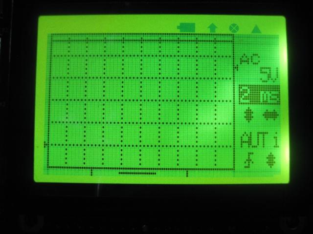
the oscilloscope is set on Auto trigg. I suspect more and more a corrupt code because I've stumbled on a curious error while taking the picture, My Mft is sending off chart readings... and my zero reading is more than a volt over my ground... I think I'll ask for a replacement from sparkfun (where I've bought it) as I've got nothing to try and reprogram the chip... I've got 4 pics attached, 1 showing my mft reading, 3 showing the "0" reading (after unplugging the probe, and after about 2 minutes)
JYE Tek
Aug 15, 2012, 11:00:07 AM8/15/12
to Le-Sid, jye-tech-os...@googlegroups.com
Ground level not at alignment could be caused by problem in the analog circuit. Please double check the soldering, particularly the slide switches.
Are the keys normal now under Auto mode?
2012/8/14 Le-Sid <theulti...@gmail.com>
--
You received this message because you are subscribed to the Google Groups "JYE Tech Oscilloscopes" group.
To view this discussion on the web visit https://groups.google.com/d/msg/jye-tech-oscilloscopes/-/gfWU8zaba9kJ.
Le-Sid
Aug 15, 2012, 8:11:28 PM8/15/12
to jye-tech-os...@googlegroups.com, Le-Sid
Ground level not at alignment could be caused by problem in the analog circuit. Please double check the soldering, particularly the slide switches.
-1. how exactly can I check the analog circuit?
Are the keys normal now under Auto mode?
2. It always been on auto mode. except for the slider switches, I never could change any options...
JYE Tek
Aug 15, 2012, 9:50:28 PM8/15/12
to Le-Sid, jye-tech-os...@googlegroups.com
For the analog channel you can make a quick check by following section 3c in the troubleshooting guide.
For the key pad problem corruped code is one possible cause. From the photos the firmware seems running properly. The cause is more likely a hardware issue. Please further confirm by moving the slide swithes. If the indicators follow the switches then we can say the firmware is good.
Possible key pad hardware problems include:
1 ) Bad switch. If one or more switches are stuck (shorted) it will fail the key detection. Open won't have affect. Checking with ohm meter should be able to find out.
2 ) Bad connection between MCU and keys. Any short or open of the connections could cause wrong key code detected and result in no action. Again please use ohm meter to check the connection throughtly.
3 ) The MCU ports for key detection are damaged. This is hard to check.
I suggest you try the 1 ) and 2 ) above to see if you can uncover the problem.
2012/8/15 Le-Sid <theulti...@gmail.com>
--
You received this message because you are subscribed to the Google Groups "JYE Tech Oscilloscopes" group.
To view this discussion on the web visit https://groups.google.com/d/msg/jye-tech-oscilloscopes/-/333r-HgggwgJ.
Le-Sid
Aug 16, 2012, 9:44:56 PM8/16/12
to jye-tech-os...@googlegroups.com
Here my results: Analog circuit with Vin @ 10,05v
Av+ : 9,15v
Av- : -7,56v
U2Pin7 : 0,0v
U1Pin1 : 0,0v
U1Pin7 : 1,04v
U2Pin1 : 1,04v
I guess my analog channel could be ok...
Push buttons all equal or under 1 ohm when pressed
However, sw1 and sw2 have some weird readings this affect only the right side of the slider switches:
-top
p1
p2
p3
spc
p4
-btm
Cental Position:P2-3 gives 0ohm but p2-4 gives me about 175ohm while sw3 gives me 0ohm
Are my sliders defective? maybe went too hot when soldered?
(and just to add insult to injury, my lcd is now blank when powered... I'll check my connections)
JYE Tek
Aug 17, 2012, 9:02:51 AM8/17/12
to Le-Sid, jye-tech-os...@googlegroups.com
For the checking slide switches resistance between poles are dependent on position. Usually you only need to check the resistance is 0 ohm (or very close to 0 ohm) or far from 0 ohm. The values that are far from 0 ohm are not important because they depend on what other components are connected. Also, always turn off power before doing connection check.
When you moved the slide switches did the indicators change?
For the buttons did they never work or work occasionally?
2012/8/16 Le-Sid <theulti...@gmail.com>
--
You received this message because you are subscribed to the Google Groups "JYE Tech Oscilloscopes" group.
To view this discussion on the web visit https://groups.google.com/d/msg/jye-tech-oscilloscopes/-/LIbDDJ0plb8J.
Le-Sid
Aug 18, 2012, 2:36:37 PM8/18/12
to jye-tech-os...@googlegroups.com, Le-Sid
All sliding switches are working correctly except for the AC-DC-Freq slider which I cannot keep on DC... it keeps going back to ac. For the buttons, I never got them to work at all...after further testing, all COL and ROW are connected correctly to the MCU... I'm kinda lost...
Reply all
Reply to author
Forward
0 new messages