V2 Test Frontend with pre-V2 Amp

John Williams
Wondering if any of the kits are finished and functional. I sent 9 of
them out.
Anxious to know how well the TX reconstruction filter works as a system
married to the amp.
Anyone have any spectrum data captured?
Any operational anomalies with the band switching.
How does power output look per band - relatively balanced and hitting
the 5W goal?
John

Sid Boyce
time.
I ordered 2 from a UK supplier via EBay expecting them to arrive Monday
or Tuesday.
Ready or collection tomorrow.
I'll build the Pre-v2 frontend using the build notes - bypassing the
PE5429's, etc. to test it with.
73 ... Sid.
Sid Boyce ... Hamradio License G3VBV, Licensed Private Pilot
Emeritus IBM/Amdahl Mainframes and Sun/Fujitsu Servers Tech Support
Senior Staff Specialist, Cricket Coach
Microsoft Windows Free Zone - Linux used for all Computing Tasks

Glenn P
Been sidetracked here with house duties. Currently tiling the floor in a large room.
I am a little concerend though that we seem to have two or three versions of re construction filter of which i have assembled one onto my v1.2 rf board. I published a sweep of it and also the Rx LPF here recently but yet to hook up to my pre V2 PA/lpf board. The latter only has one lpf fitted and no relays.
I did receive the 12 way IDC sockets though yesterday from ebay.
I am also unsure which transformer version one should be using on the RF board for the Rx input? I wound mine according to the wiki info. But the 1.2 RF Sch shows a different ratio?
I am also have difficulties with PowerSDR on my new PC. I installed it on a Win8.1 PC but cannot get any audio output from it, when connected to H-L. I followed the instructions to install P/sdr on the wiki but alas, no worky. Alans software works just fine though. Its the only PC i have that is 64 bit windows and grunty.
glenn
vk3pe

Steve Haynal
John Williams
Per the wiki, did you setup the VAC1 screen and enable it "Next, to hear audio, enable VAC1 as identified by a red arrow near the bottom as shown below. Unlike the Hermes, the Hermes-Lite has no onboard audio DAC so virtual audio must always be used."
Select the appropriate input and output devices on the screen. Then click the enable option on the upper left corner.
Also, on mine, I have to select the stereo option on the VAC1 screen to get audio.
I can send a screenshot if you need one.
John
--
You received this message because you are subscribed to the Google Groups "Hermes-Lite" group.
To unsubscribe from this group and stop receiving emails from it, send an email to hermes-lite...@googlegroups.com.
For more options, visit https://groups.google.com/d/optout.
Glenn P
but just in case a screen shot may help....... i am stumped. I had no such problems on my Win7 Laptop. Its just worked. I am not a PC nerd. (nor any other nerd)
The new PC is an Pent I7 running win8.1. Works just fine with Alans software which i have tried for WSPR decoding (works great) But really want PowerSDR on the new PC.
glenn
Glenn P
I do think its best to all test using the same hardware as much as possible. Get more meaningful results for the20% or at least find if on the wrong track.
glenn

Stew KF5KOG
Stew KF5KOG
On Wednesday, November 18, 2015 at 4:30:54 PM UTC-5, John Williams wrote:
John Williams
See my wiki article. Tx is same and rx is 8:1 with no center tap. Also, I skipped the rx filter. Not performing well.
--
kf5kog
Stew KF5KOG
On Wednesday, November 18, 2015 at 4:30:54 PM UTC-5, John Williams wrote:
John Williams
The filter that we are trying now for TX is in the wiki. Unfortunately this got chosen after I built the kits. You may be able to get close if you have some 100pf caps and using the 270nh and 390nh in the kit. Just double the 100pf caps for 200pf. Since we have a 10M roofing filter on the amp, I skipped the RX filter.
John
--
Stew KF5KOG
On Wednesday, November 18, 2015 at 4:30:54 PM UTC-5, John Williams wrote:
John Williams
The main concern with the TX reconstruction filter is suppression of spurs in the VHF and up regions. Can you run a spectrum analysis into that frequency range? We need to have all spurs be a minimum 60db down above 30MHz.
Thanks for your help,
John - W9JSW
--
Glenn P
My post also shows the values used.
Only plotted though to 200Mhz from memory and the suppression was getting worse as freq went up...... some due to radiation in test setup between cables but not all.
glenn
Stew KF5KOG
On Wednesday, November 18, 2015 at 4:30:54 PM UTC-5, John Williams wrote:
John Williams
Was thinking that a measurement with hand wound toroids would be another data point.
Glenn P
is your reconstruction filter built per the Sch on the wiki? We tested that before, Graeme and I and at the time concluded that the spread of parts meant that it was probably not repeatable.
The test I did was using the the 7 pole version 100p, 330uh,200p,390uH,200p,330uH,100p
Glenn
John Williams
Correct me if I am wrong, but I think the issue with repeatability was with the 17M/15M filter.
I thought that the TX reconstruction filter was pretty solid. You used SMD components, correct? Stew used had wound components.
Am I recalling this correctly?
John
--
kf5kog
--
Glenn P
But for some reason I thought we decided on the 100p, 330nh,200p,390nH,200p,330nH,100p filter ?
You can see from my and Stew's results that they are vastly different in attenuation of around 60MHz for example.
I used all SMD parts in my build on the pre v2 RF 1.2 pcb. The 330nH were 0603, (Q=25) the 390nH as supplied, 0805? ( I have a small kit of smd inductors, 0603)
Caps all 0603
glenn
Glenn P
ie you have a fully built Tx chain.
I don't have this. I have only tested filters in isolation.
My prev2 RF1.2 is fully loaded with values as stated. 100p, 330nh,200p,390nH,200p,330nH,100p
My preV2 5W board has one filter only fitted....17/15m ? No relays yet either.
So I am not in a position yet to do a full system test. [I also need to somehow get my PC to work with PowerSDR. Not tried it again as yet]
glenn
kf5kog
John Williams
Perhaps the Q of the hand wound toroid is significant?
Glenn P
Not really related to this thread but I can hear -130dBm from the HP8640B sig gen with Alan's ap. on 40M. That's directly into the V1.2 front end which is fitted with all parts.
But Only can hear about -100dBm signal on PowerSDR...... I would assume that i have a setting wrong in Psdr.
glenn
On Tuesday, November 24, 2015 at 11:25:36 AM UTC+11, John Williams wrote:
Perhaps the Q of the hand wound toroid is significant?
On Mon, Nov 23, 2015, 6:04 PM kf5kog <stewk...@gmail.com> wrote:
On Mon, Nov 23, 2015 at 6:53 PM, Glenn P <glen...@gmail.com> wrote:
snipped:---
John Williams
John Williams
John
--
Stew KF5KOG
Steve Haynal
- T1 for TX was wound on a BN-43-2402 as per the original frontend, 4T bifilar on AD9866 side (8T with center tap) and 6T on filter side for (8.0/6.0)^2 = 1.78 impedance transformation?
- A 100 Ohm resistor was added across the AD9866 side of T1 to reduce power as per John's latest wiki instructions?
- Instead of AIML SMT inductors, you wound your own on T37-10 cores?
- Did you reduce power at all by audio level or power level adjustment in PSDR?
John Williams
--
John Williams
I think using a 4 layer board with the filters on the top and the copper
layer on level 2 makes the filters perform superior to a 2 layer board.
Using this on the PA has given us much more repeatable results from
initial testing on a breadboard to similar performance in circuit. I
have no way to validate it but am guessing that the stray capacitance is
much lower on the 4 layer board.
Just my 2 cents...
John
On 12/7/2015 12:40 AM, Steve Haynal wrote:
Glenn P
I imagine if you didn't clear the internal copper under the filters then the capacitance from either side to next copper capacitance will be higher.
glenn
John Williams
The total thickness is 1.6mm so your typical is correct. The layout is filters on top, copper on next, power on next and control traces on the bottom, for the most part.
What would be your hypothesis on this? Is it perhaps because of managing impedance to and from the relays?
John
kf5kog
--
Glenn P
for that pcb layup, the calculated track width for a 50R track is approx 20mils (0.5mm) . I doubt that at HF, though there is much to gain by changing it from whatever it is now.
On Tuesday, December 8, 2015 at 8:46:14 AM UTC+11, John Williams wrote:
Glenn,
The total thickness is 1.6mm so your typical is correct. The layout is filters on top, copper on next, power on next and control traces on the bottom, for the most part.
In a past life at higher freqs we used to clear the layer down to reduce capacitance effects but I think the relatively small 'C' induced will be swamped by the filter values anyway in most cases.
glenn

in3otd
for that pcb layup, the calculated track width for a 50R track is approx 20mils (0.5mm) . I doubt that at HF, though there is much to gain by changing it from whatever it is now.
The filters ultimate rejection depends on a lot of details, I'll expect that the coupling between the biggest components (toroids, relays) is one of the main contributors to that.
In a past life at higher freqs we used to clear the layer down to reduce capacitance effects but I think the relatively small 'C' induced will be swamped by the filter values anyway in most cases.
yes, I've done this a lot, but always in the GHz+ range. If someone has a TDR it will be interesting to see where the discontinuities are, just out of curiosity. But if you use the appropriate risetime (about 10 ns for a 30 MHz BW) I guess you won't see much.
73 de Claudio, IN3OTD / DK1CG
Stew KF5KOG
Stew KF5KOG
On Monday, December 7, 2015 at 1:40:33 AM UTC-5, Steve Haynal wrote:
in3otd
Hello Stew,
why the TX out at 29 MHz reads out at about -7 dBm? Is
there an attenuation/offset in the readings that needs to be taken into
account?
For comparison I'm enclosing a couple of pictures taken
with my setup, which is slightly different than yours (for T1), hope
this does not add confusion:
H-L
with v1.2 Basic Frontend, TX transformer T1 there with a 4 turn
winding and a 6 turns with center tap on a BN-43-2402 core, 100 ohm
termination on the AD9866 IOUT output (R2) . TX output filter on the frontend board 100p, 330n, 200p, 390n, 200p, 330n, 100p, no ground braid added.
TX at 29.0 MHz, power output +10 dBm, which is slightly below the maximum I can get with this configuration.
Spectrum without the TX filter (directly at the T1 output):

Spectrum with the TX filter (at the P1 output on the frontend, T1 output jumpered to the filter input):

As you can see, I have no 7.509 MHz spur, but I can see the 44.728 MHz one (and the 2.456 MHz is maybe a couple of db higher with the filter)...
73 de Claudio, IN3OTD / DK1CG
Glenn P
I have the 100R fitted to mine also. Same values for re construction filter so it will be interesting.
glenn
glenn
Stew KF5KOG
Glenn P
glenn
in3otd
as Glenn said, to input to the SA is likely too high. How much attenuation is needed depends on the particular SA type, of course, but FYI I have an external 20 dB attenuation (this is the reason of the "20 dB offset" message on the screen) and the SA is adding another 20 dB internally.
73 de Claudio, IN3OTD / DK1CG
Stew KF5KOG
Steve Haynal
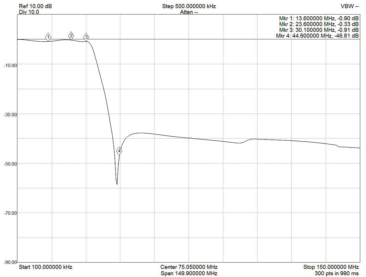
Glenn P
Basically compared the basic RF V1.0 to the V1.2 board.
The V2 board was tested with and without the 100R across T1.
All tests done at 29MHz as Stew has done.
I didn't interpret the result too much, others may draw some conclusions from them. But it would seem the output is very clean apart from the consistent output at approz 150MHz (which may actually be 2 x the 72.xMHz Ref xtal? SA's are not renowned for absolute freq. accuracy.
With the 100R fitted, output of around +10dBm is achieved with drive setting of 100.
Sorry, no time to measure other bands.
see attached pdf:
glenn
vk3pe
Stew KF5KOG
Glenn P
glenn
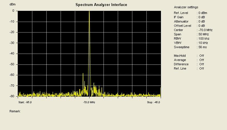
Glenn P
The drive of 32 was done to reduce the wanted 29MHz by 10dB to see the effect on the 2.4MHz and other 'spurs'.
Definately affected by 'something' in the AD9866
see attached:
glenn
]vk3pe
Steve Haynal
Glenn P
I will have a look closer in at the '150MHz' spur to see what it is asap.
Off the subject, but:
MY H-L is in pieces right now. I decided to tidy it up a little by mounting all the boards on top of a blank piece of PCB material. Mounted on metal spacers. Found it no longer works ! The problem or cause is that if the LAN adapter board is grounded through metal spacer also, then nothing works. Power drain is only 50mA...... pulled out the spacers on LAN and its working again. Have to find some plastic ones. (the return path is from RF board mount screws, ground track is very close to mounting screw heads and shorts it seems.
glenn
vk3pe
Glenn P
Glenn P
I did a test at 24.895MHz and can see what appears to be your alias of 22.981MHz although the marker is a little out in reading freq. (but centre marker is ok so not sure) Dropping drive to reduce the wanted signal by 10dB also drops the '22.891' a like amount, or very close, 11dB
The closer in spurs appeared also at the 29MHz test and are approx +- 1MHz from wanted signal.
RE the reconstruction filter, i recall that doing an analysis of it using RFSim99 shows that this filter does have a fair degree of loss approaching 30MHz. Tolerances may affect this even more. My build uses a 390nH supplied by John and 330nH WW from my collection.
You may note that I actually get more output (+11dBm at 24.895MHz) than what I was getting in other tests at 29MHz which would confirm a roll-off higher up..
On Monday, December 14, 2015 at 12:57:06 PM UTC+11, Steve Haynal wrote:
Hi Glen,Thanks for the ;measurements and reports. They are very informative.Do you think your ~150 MHz spur could be 73.728*2=147.456 MHz? In the full-duplex version, this clock is generated on the interface of the FPGA and may be radiating some. You could try shielding the Hermes-Lite. You could also try the half-duplex firmware as that runs on v 1.22 too.It is interesting that you see a reduction in the 2.4 MHz spur for power reduction. My experiment where I did not see reduction in this aliased back DAC spurs was for the 22.981 MHz spur when TX at 24.895. What behavior do you see at that frequency? Other differences are the 100 Ohm resistor, and the reconstruction LPF in place.With my build of the LPF (100p, 330nh,200p,390nH,200p,330nH,100p) using AIML inductors, I see losses in the filter from about 1 dB on 40 M to 4 dB on 10 M. It doesn't appear that others see this. Is that true? There may be a problem with my build.73,SteveKF7O
snipped:
John Williams
Steve Haynal
On Sunday, December 13, 2015 at 10:53:09 PM UTC-8, Glenn P wrote:
OK Steve, the spur is not 2x 73.728. It appears to be the 3rd harmonic of the LAN interface xtal (50MHz) Touching around the xtal brings the level up and down.
I did a test at 24.895MHz and can see what appears to be your alias of 22.981MHz although the marker is a little out in reading freq. (but centre marker is ok so not sure) Dropping drive to reduce the wanted signal by 10dB also drops the '22.891' a like amount, or very close, 11dB
The closer in spurs appeared also at the 29MHz test and are approx +- 1MHz from wanted signal.
RE the reconstruction filter, i recall that doing an analysis of it using RFSim99 shows that this filter does have a fair degree of loss approaching 30MHz. Tolerances may affect this even more. My build uses a 390nH supplied by John and 330nH WW from my collection.
You may note that I actually get more output (+11dBm at 24.895MHz) than what I was getting in other tests at 29MHz which would confirm a roll-off higher up..
Glenn P
I have no explanation for the ~2MHz alias not following the wanted signal.
glenn
in3otd
Hello,
I have measured the output level of some harmonics and
spurs/images when varying the fundamental output level. I have used the
Quisk routines for the "spot level" control to change the TX output from
0 to 1000, with the TX frequency fixed at 29 MHz. Level were recorded
without the TX output filter, i.e. just after the T1 transformer on the
V1.2 frontend.
With the spot level at 1000 I get around 13 dBm, while for having 10 dBm the level to use is around 665 here. As known, the output spectrum degrades rapidly when going towards the maximum output power.


Graphs and the full data file are also on my website.
I'll try to do the same graphs for the TxDAC output.
73 de Claudio, IN3OTD / DK1CG
Hi Glen,

James Ahlstrom
in3otd
yes, if I understood the code correctly, the spot level changes the DC level at baseband, right?
The TX power level was fixed at 255 but I can try to run a test varying it; I guess this control has a more limited range looking at the AD9866 datasheet (did not check what the verilog code does)
For the TxDAC testing, if I understood correctly, I need to change the AD9866 init code (the part done in MyHDL); last time I looked at that it was not so clear to me how it worked...
73 de Claudio, IN3OTD / DK1CG
Sid Boyce
with the build.
From 2 emails I have printed off.
1. 12/8/15 -- Steve says T2 is 8T (no centre tap) with 100 ohm across
the winding --> CN1 and 14T --> filter.
2. The frontend Filter can be bypassed with T1 secondary wired directly
to P1 as the PA provides the filter - John 11/05/15.
Already did the Regulator Bias voltage mod in Pre-V2-Amplifier-Errata.md.
73 ... Sid.
--
Sid Boyce ... Hamradio License G3VBV, Licensed Private Pilot
Emeritus IBM/Amdahl Mainframes and Sun/Fujitsu Servers Tech Support
Senior Staff Specialist, Cricket Coach
Microsoft Windows Free Zone - Linux used for all Computing Tasks
John Williams
Can't answer now, away from computer, but errata article is correct.
--
You received this message because you are subscribed to the Google Groups "Hermes-Lite" group.
To unsubscribe from this group and stop receiving emails from it, send an email to hermes-lite...@googlegroups.com.
For more options, visit https://groups.google.com/d/optout.
James Ahlstrom
yes, if I understood the code correctly, the spot level changes the DC level at baseband, right?
The TX power level was fixed at 255 but I can try to run a test varying it; I guess this control has a more limited range looking at the AD9866 datasheet
For the TxDAC testing, if I understood correctly, I need to change the AD9866 init code (the part done in MyHDL); last time I looked at that it was not so clear to me how it worked...
Steve Haynal
Glenn P
Steve Haynal
Steve Haynal
Glenn P
glenn
vk3pe
in3otd
I have briefly played with the TX power control and the range is about 19 dB as expected, but the last codes give all the same (max) ouptut power and not the expected 0.5 dB steps, so there is a bigger step toward the end. I tried to understand how the power is controlled, but it's not completely clear to me. AFAIU you are changing the TxPGA code and the IAMP current ("primary path gain"). Shouldn't be enough to change the TxPGA code? I guess the steps which are actually constant are these. I tried changing them but I got 10 dB less power on all steps, which does not make sense to me.
Besides, I saw that the AD9866 datasheet briefly mentions the IOFF internal current sources that can be used for a "marginal improvement in distortion performance under large signal conditions", without further details and I wanted to check whether this can help for the spurs we see. I hacked ad9866.v to include the previously unused step #17 and change the IOFF1 value using the register at 0x12, tried to set it to 2 and 4 but in all cases I get a corrupted, noise-like, output. Did you already try to change the IOFF1 value? Do you have further details on how that should be used?
73 de Claudio, IN3OTD / DK1CG
in3otd
Hello,
by popular demand (hi), here are the fundamental, harmonics spurs, etc, vs the TX drive level (C1 byte for C0=0b00010011).
TX frequency was 29 MHz, spot level at max (1000). As before, the measurements were done
without the TX output filter, i.e. just after the T1 transformer on the
V1.2 frontend.
First graph is the fundamental alone, just to show the bigger step at the end (note the small downward slope there, initially I thought it was a thermal drift, but apparently it's not)

and here are the graphs for the other relevant signals


It seems that the bigger increments in the distortion products occur when changing the IAMP gain (but the 2nd harmonic is somewhat an exception). The true images follow mostly the fundamental output, as they should. Note that the fixed spur at 2*fs behaves like a distortion product (?).
73 de Claudio, IN3OTD / DK1CG
Hi Claudio,Thanks for the measurements. I always appreciate your clear graphs. I too would be interested in the differences when adjusting TX power versus DAC amplitude. The TX power range should be ~19 dB. If you alter ad9866.py, you have to "compile" and generate Verilog that Quartus consumes. You can also hack the verilog file ad9866.v.73,SteveKF7O

in3otd
...sorry for the repeated postings,
I thought it was interesting to
show how the graphs look like when plotted in dBc, i.e. level of the
harmonics/products/spurs w.r.t the fundamental level.
It turns out
that the TxDAC is actually cleaner when at maximum gain (in general) (while increasing the IAMP gain causes a increase in the distortion, as expected):

73 de Claudio, IN3OTD / DK1CG
James Ahlstrom
in3otd
Hello Jim,
I have now done some measurements on the TxDAC output, with the IAMP disabled, using a center-tapped 1:1 transformer, as described in your post and in the AD9866 datasheet. The TX frequency was 28.895 MHz this time. Indeed, the output of the TxDAC alone is much cleaner:


Strange that the IAMP has a strong effect on the 2fs-5ftx type of spurs, as it doesn't have a very strong component at fs at its input; I thought it might come from the TxDAC when loaded by the IAMP, so I tried to do some experiments loading the IOUTP output in various ways when using the IAMP, but did not manage to improve the distortion.
73 de Claudio, IN3OTD / DK1CG
Steve Haynal
Steve Haynal
Hi Claudio,
James Ahlstrom
in3otd
yes, I meant fs=73.728MHz and as you said the TxDAC is a sampled system which works at 2*fs so I can understand that its circuitry can generate harmonics of the transmit signal ftx which are then aliased around 2*fs.
But looking at the datasheet the IAMP seems a "normal" amplifier (continuous time, not sampled) so I will expect it to amplify (and generate intermodulation products) of its input signals. Looking at the measurements the carrier at 2*fs at the output of the TxDAC is relatively low (-50 to -60 dBm) and the tx fifth harmonic is between -70 and -80 dBm. If the 2*fs-5*ftx product at the output of the IAMP was due to intermodulation in the IAMP I would have expected it to be much smaller then the input components. To have aliases of the harmonics the IAMP generates it should also be a sampled system, which seems not be the case, at least looking at the datasheet.
To expand a bit more on the experiments I mentioned in the previous post, I noticed that when the TxDAC+IAMP are used the common mode of the TxDAC output (on the IOUTP pins) is around 1.3 V. But when using the TxDAC alone, the datasheet recommends to connect the transformer center tap to ground, so the common mode is now 0V. The measurements above are done it this condition.
I have then lifted the transformer center tap from ground, bypassed with a good 1 uF capacitor and changed the voltage on the tap, effectively changing the common mode of the TXDAC output. I saw that until 1.2/1.3 V the bias current does not change, so that seems to be the allowed common-mode range. But I saw that already when using a 1.0 V bias on the center tap the products at the TxDAC output degrade quite a lot, some even by 20 dB. I have the measurements data somewhere.
So it seems that also the bias on the TxDAC output can have a significant impact. But, as known, unfortunately the TxDAC and IAMP are DC coupled so we cannot do anything on this.
Strange is that the datasheet says "the TxDAC voltage compliance is around 1.2 V" but then it is biased to 1.3V when using the IAMP. Maybe the circuit is much more complex than shown in the datasheet, so the allowed common mode changes when the IAMP is used.
Another experiment that I wanted to try is to put a series trap at 2*fs between the IOUTP_+/- pins; honestly do not expect it to do much. If this is confirmed the products are likely already at the TxDAC output and due to the different biasing conditions when using the whole chain.
73 de Claudio, IN3OTD / DK1CG
James Ahlstrom
in3otd
will try to do this measurement in the next days, currently I had to put aside my H-L to make room on the bench for servicing a much bigger non solid-state amp, hi.
73 de Claudio, IN3OTD / DK1CG
James Ahlstrom

Joe
James Ahlstrom
Steve Haynal
Joe
in3otd
interesting result with the series tank, maybe it's actually resonating at 2*fs, about 147 MHz, with the long PCB traces?
If you wish, I can recompile the current code for you, disconnecting the IAMP and recomputing the gain steps, let me know which BeMicro board you have there (SDK/CV/CV A9 ?).
73 de Claudio, IN3OTD / DK1CG
Joe
in3otd
Hello Jim,
here is the TxDAC output vs. common-mode bias (on the transformer center tap).
The TX frequency was 24.895 MHz, output power at max (around 5 dBm), which is more than the 0.4 V peak you mentioned, but should give some margin, hi.
As you can see, the 2*fs-5*ftx spur is fine until about 0.6/0.7 V bias.


73 de Claudio, IN3OTD / DK1CG
in3otd
enclosed is the current code compiled for the SDK (non-FD, 73.728 MHz clock), modified to disconnect the IAMP (and setting its gain to zero) and remapping the 0 to 255 TX level code to the sixteen 0.5 dB TxDAC levels (so the output actually changes every 16 TX level steps). I have compiled and tested the code for my CV A9 also and it works fine there, so there are good chances it works on your SDK as well, hi.
73 de Claudio, IN3OTD / DK1CG
James Ahlstrom
Joe
Joe
in3otd
not sure I'm reading the graphs correctly, I will expect even lower spurs from the TxDAC output. My measurements (and Jim's) show that when transmitting at 24.895 MHz the spur at 22.981 MHz is at around -72 dBm; the carrier is at around 5 dBm so this will be -77 dBc, your numbers seems to be much higher...
73 de Claudio, IN3OTD / DK1CG
Joe
in3otd
73 de Claudio, IN3OTD / DK1CG
Joe
in3otd
Joe,
in the "new firmware" table below, there is a 10.9 (dBm) in the "PWR out" column; can you obtain that power from the TxDAC alone? In theory you can get only slightly more than 5 dBm when using the 1:1 center-tapped transformer and this is the power I and Jim measured.
In the "original firmware with trap" you have a +19 dBm output, but from the IAMP with the 2:1 transformer and 100 ohm of backtermination (R2 on the main board) you should get +14 dBm at maximum.
I think there are some differences in the actual circuits we are testing...
73 de Claudio, IN3OTD / DK1CG