Hysteresis with a 555 timer
713 views
Skip to first unread message

Jason
Nov 24, 2012, 1:42:58 PM11/24/12
to diyr...@googlegroups.com
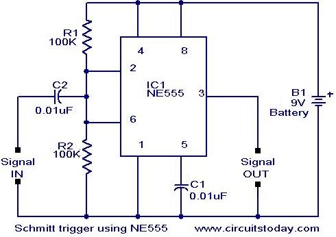
I've been working to add wheel encoders to my car and found a nice solution for hysteresis using a 555 timer. Just send the signal from the encoder (IR sensor in my case) to the 555. It switches high when the rising edge is 1/3 of the supply voltage and low when the falling edge is 2/3 the supply voltage. I haven't tested it on my car but it worked well using a test jig I set up to have it output the rotation speed and position of a servo.
Jason
Nov 24, 2012, 1:48:00 PM11/24/12
to diyr...@googlegroups.com

Ted Meyers
Nov 25, 2012, 11:06:57 PM11/25/12
to diyr...@googlegroups.com
Hey, that looks like an easy trick! I'll have to try it next time I'm building encoders. Thanks!
Ted

wholder
Nov 27, 2012, 6:30:36 PM11/27/12
to diyr...@googlegroups.com
You can also use a "schmitt buffer" for this. For background, check out this link:
http://www.ti.com/lit/an/scea046/scea046.pdf
For 90 cents, you can get 8 of them in a single, DIP package:
http://www.mouser.com/ProductDetail/NXP-Semiconductors/74HC7540N112/?qs=sGAEpiMZZMtOwpHsRTksowxVT%2f9EkYvNJI0jJ3u%252bhh0%3d
which will handle several encoders. Or, you can get just two of them for just 12 cents in a very compact, SC-70-6 surface mount package:
http://www.mouser.com/ProductDetail/Fairchild-Semiconductor/NC7WZ17P6X/?qs=sGAEpiMZZMswyCOIqqEme4a7Z5jQBVdNTca6IfaMx1Q%3d
other vaariants are shown by this search:
http://www.mouser.com/Semiconductors/Integrated-Circuits-ICs/Logic-ICs/_/N-6j77x?Keyword=schmitt+buffer&FS=True
Wayne

Michael Shimniok
Nov 27, 2012, 6:36:30 PM11/27/12
to diyr...@googlegroups.com
The logic Schmitt triggers would work at logic levels right? Versus 1/3 and 2/3 VCC ?
To view this discussion on the web visit https://groups.google.com/d/msg/diyrovers/-/QgS7q5PO7uoJ.
--
You received this message because you are subscribed to the Google Groups "diyrovers" group.
To post to this group, send email to diyr...@googlegroups.com.
To unsubscribe from this group, send email to diyrovers+...@googlegroups.com.
wholder
Nov 27, 2012, 6:54:22 PM11/27/12
to diyr...@googlegroups.com
On Tuesday, November 27, 2012 3:36:30 PM UTC-8, Michael Shimniok wrote:
The logic Schmitt triggers would work at logic levels right? Versus 1/3 and 2/3 VCC ?
Not exactly. The purpose of a Schmitt "trigger" (whichi is what these buffers implement) is to add hysteresis. According to the spec for the 74HC7540N (the DIP package) the hysteresis voltage is .4 volts when VCC at 4.5 volts, so it's a bit less than what you'd see with the 555, but should work fine for an encoder as long as there's not a lot of high frequency noise (a simple RC low pass could fix that, though.)
Wayne
Michael Shimniok
Nov 27, 2012, 9:39:24 PM11/27/12
to diyr...@googlegroups.com
On Tuesday, November 27, 2012 3:36:30 PM UTC-8, Michael Shimniok wrote:The logic Schmitt triggers would work at logic levels right? Versus 1/3 and 2/3 VCC ?Not exactly. The purpose of a Schmitt "trigger" (whichi is what these buffers implement) is to add hysteresis.
I know :) I didn't explain myself as usual. :) I expected the hysteresis to be sort of asymmetrical between 0V and Vcc. Like 50% and 10% of Vcc instead of 70% and 30% Vcc. As a lot of logic circuits have a rather low high threshold.
According to the spec for the 74HC7540N (the DIP package) the hysteresis voltage is .4 volts when VCC at 4.5 volts, so it's a bit less than what you'd see with the 555, but should work fine for an encoder as long as there's not a lot of high frequency noise (a simple RC low pass could fix that, though.)
According to the datasheet Vt+ is 70% Vcc and Vt- is 30% Vcc at 4.5V and 6V just like the 555. Cool. So, I was wrong :)
On the other hand, at 2V it's 15% and 5% Vcc... I'm sure various lower voltage logic families would cover for my 3.3V system. Here's one. http://www.ti.com/lit/ds/symlink/sn74aup2g17.pdf ranges from ~40%/60% to ~30%/70% ... That device is a dual schmitt trigger in an SC70-6 for about $0.50 in low quantities.
Nice thing about the 555 is you can do up a variable hysteresis circuit pretty easily. If one needs it.
Michael
Jason
Nov 27, 2012, 10:11:23 PM11/27/12
to diyr...@googlegroups.com
Thanks! I hadn't heard of those before. I already designed the 555 into a PCB I'm having made but I'm going to order a few of those and test them out.

Scott Harris
Nov 27, 2012, 10:48:57 PM11/27/12
to diyr...@googlegroups.com
Tobor uses a 7414 with the optical encoders. Works great.
-Scott
Michael Shimniok
Jan 9, 2013, 2:14:09 PM1/9/13
to diyr...@googlegroups.com
So how's the encoder board going? I gave the 555 thing a try. Me no happy. :) Here's what happened.
They key point is that the waveform out of the QRE1113 breakout, fed by 3.3V, is only 1.8V peak on my robot. The 555NE I'm using won't trigger off that. My own Schmitt board has thresholds selected to work with the SFE QRE1113 breakout.
So how to make the 555 work? One can put a smallish capacitor inline to high pass filter the signal (converting it to AC, basically) and feeding it into the middle of a voltage divider giving it a 1/2 * Vcc DC offset. Even at only 1.8Vpp the 555 triggers. Cool.
However, there's a speed threshold below which you'll get no pulses. The threshold with a 0.1uF cap isn't too bad. For race purposes where the robot isn't stopping and goes fast, the missed pulses will be very few. For a very slow bot or one that stops and starts a lot, lots of distance will go unmeasured.
One can use a larger cap -- I tried a 47u, 100u and 200u. However, the 555 can get 'stuck' when the wheel stops. If the input voltage is low, 555 output high, then the wheels start turning, the 555 switches low and stays there. The only way to unstick is for input voltage to go high for a little while. Similarly, if the input is high and output low and stays that way for long enough, it takes several pulses before the 555 starts triggering again.
I will have to go refresh my EE memory a bit and look at what's inside a 555 to determine precisely what's going on. I may have an inkling, but as they say better to remain silent and be suspected a fool than speak and confirm it beyond all doubt. :)
I still like "my" board (I say my but it's really a design I lifted off the interwebs) even though I detest assembling them due to the many small passives. What I like is that the board pulses at all speeds. It has downsides of course. The waveform isn't perfectly square and if the sensor is at the edge of a stripe the voltage can be 'in between'. So I guess it doesn't actually behave as a "real" schmitt trigger, but it does (sort of) square up the waveform and it definitely amplifies the signal to logic levels.
Michael
Wayne Holder
Jan 9, 2013, 3:01:59 PM1/9/13
to diyr...@googlegroups.com
Michael, which version of the SFE QRE1113 are you using the analog, or the digital output?
Wayne
Wayne
Ted Meyers
Jan 9, 2013, 11:05:43 PM1/9/13
to diyr...@googlegroups.com
The odd thing about the digital version is that it is not really digital.
wholder
Jan 10, 2013, 1:08:17 AM1/10/13
to diyr...@googlegroups.com
They key point is that the waveform out of the QRE1113 breakout, fed by 3.3V, is only 1.8V peak on my robot. The 555NE I'm using won't trigger off that. My own Schmitt board has thresholds selected to work with the SFE QRE1113 breakout.
You might try the TLS555 from TI. It can run from 2 volts up to 15 volts, so it should work fine with 3.3 volts. See:
It's also much lower power consumption than a standard 555.
Wayne
Michael Shimniok
Jan 10, 2013, 1:28:02 AM1/10/13
to diyr...@googlegroups.com
I'm using the analog version.
I did a some more LTspice simulation and more experimentation and I think I see what's going on. The circuit essentially readjusts the signal offset to the low voltage. When the wheel starts spinning, it takes a long time to bleed the dc offset back down to where it should be.
I found a better circuit; simply amplify the encoder signal with an NPN and do away with the series capacitor. It's not hard to saturate the transistor with the QRE1113 signal then feed the output into the 555.
Anyway this version worked like a charm. It triggers on very slow wheel speeds and no missed pulses as with the series cap version. The pulsetrain is a bit unbalanced but software can deal with that.
I modded my 555 board with this design after prototyping. But I then realized a 74LVC2G14 (two-gate 74*14) in SOT23-6 would be much smaller and should work just as well. The resulting board is a bit less than 3/4" x 3/4" with a lower parts count than my prior design. I may go ahead and run a few boards and try 'em.
Michael
--
You received this message because you are subscribed to the Google Groups "diyrovers" group.
To post to this group, send email to diyr...@googlegroups.com.
To unsubscribe from this group, send email to diyrovers+...@googlegroups.com.
To view this discussion on the web visit https://groups.google.com/d/msg/diyrovers/-/OOiGClf7XaoJ.
Jason
Jan 12, 2013, 8:25:00 PM1/12/13
to diyr...@googlegroups.com
Glad you got it working. I actually had the opposite problem. I had my 555 powered at 5V and had to step it down to 3.3V logic for the micro. I just sent the signal through an LED which had the added bonus of a nice visual indicator.
You can see them flashing in this video.
Michael Shimniok
Jan 13, 2013, 5:28:28 PM1/13/13
to diyr...@googlegroups.com
Looks great! Glad you got it working.
I wonder if part of the reason for my 'odd' signal is because the encoder stripes are very narrow.
I'm envious of your mainboard. Mine is home etched and looks like poop. :) What is your main processor again?
Michael
To view this discussion on the web visit https://groups.google.com/d/msg/diyrovers/-/qJN7-GKwuSEJ.
Jason
Jan 13, 2013, 7:20:55 PM1/13/13
to diyr...@googlegroups.com
Thanks! I'm using the chipkit Max32. It's a PIC micro.
I still need to add code for the encoders though.

Michael
Jan 14, 2013, 9:32:02 AM1/14/13
to diyr...@googlegroups.com
What I did for my home brew encoders was use a comparator circuit which allows for adjusting both hysteresis levels by changing resistors, no capacitors involved. I am also using QRE1113 sensors.
Here is info on that technique:
I just thought I'd throw that out there as another option for those that haven't already built a circuit board for the 555.
Michael Sprague
On Wed, Jan 9, 2013 at 2:14 PM, Michael Shimniok <shim...@gmail.com> wrote:
So how's the encoder board going? I gave the 555 thing a try. Me no happy. :) Here's what happened.They key point is that the waveform out of the QRE1113 breakout, fed by 3.3V, is only 1.8V peak on my robot. The 555NE I'm using won't trigger off that. My own Schmitt board has thresholds selected to work with the SFE QRE1113 breakout.So how to make the 555 work? One can put a smallish capacitor inline to high pass filter the signal (converting it to AC, basically) and feeding it into the middle of a voltage divider giving it a 1/2 * Vcc DC offset. Even at only 1.8Vpp the 555 triggers. Cool.
Michael Shimniok
Jan 21, 2013, 2:37:41 PM1/21/13
to diyr...@googlegroups.com
That's what I did for the original circuit. Works great. I built a tiny SMT version but it's a lot of parts. At some point I'm going to look at transistor + Schmitt logic gate (single or double) in SMT form.
wholder
Jan 21, 2013, 2:51:20 PM1/21/13
to diyr...@googlegroups.com
Michael, take a look at:
http://www.fairchildsemi.com/ds/NC/NC7WZ17.pdf
it's available in an SC-70 package and works from 1/6 to 5.5 volts, so you can use it for both 3.3 and 5 volt logic. Oh, and it costs 12 cents...
Wayne
http://www.fairchildsemi.com/ds/NC/NC7WZ17.pdf
it's available in an SC-70 package and works from 1/6 to 5.5 volts, so you can use it for both 3.3 and 5 volt logic. Oh, and it costs 12 cents...
Wayne
Michael Shimniok
Jan 21, 2013, 3:01:54 PM1/21/13
to diyr...@googlegroups.com
Perfect, thanks!
Sent from my iPhone
Sent from my iPhone
--
You received this message because you are subscribed to the Google Groups "diyrovers" group.
To post to this group, send email to diyr...@googlegroups.com.
To unsubscribe from this group, send email to diyrovers+...@googlegroups.com.
To view this discussion on the web visit https://groups.google.com/d/msg/diyrovers/-/382xKuZ8fMEJ.
Reply all
Reply to author
Forward
0 new messages