
Glenn Elmore
Frequency Stability & Accuracy for VHF+ WSPR
I'm starting this thread to create a place to discuss issues related to getting amateur equipment stable enough to successfully decode and generate WSPR signals as well as to discuss the value and means for having high absolute frequency accuracy as well.
Stability
Almost all of us who have put our stations on 2 m (or above) WSPR have had to deal with getting sufficient stability to allow good operation. What would pass as acceptable drift on 20 m is ten times worth and unusable by 2 m. By 1296 MHz, the problem has escalated another order of magnitude.
Generally frequency stability can be measured a number of ways, drift in Hz or ppm per second, minute, hour, day, year etc. For our purposes the critical time frame is the 2 minute WSPR window. Unless end-end signals show up with frequency change less than 3-4 Hz within two minutes, the station may not be usable for WSPR.
At 144 MHz, 1 Hz drift amounts to 1 Hz/144e6 = which is 7 parts/billion and less than a millionth of one percent. This is a much smaller value than the specifications on even the best high-stability frequency references for Icom, Yaesu or Kenwood transceivers. Normally these specifications are not very detailed and may not tell the radio owner much about the stability in an interval as short as 2 minutes but they do give an indication of the problem.
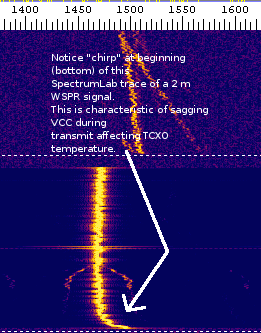
We do have stations on 2 m WSPR that are successfully operating both Icom and Yaesu hardware with the high-stability timebase but it's not guaranteed that this will work. Some radios do pretty well and some are marginal or unusable. In addition to temperature drift, particularly due to the entire RF deck warming/cooling during transmit/receive, there may be voltage dependence of the TCXO. The Icom unit has a characteristic “chirp” during the first 10-20 seconds of transmit when used in IC746, IC910 and perhaps other radios. Cutting the 14 VDC connection to the TCXO and inserting a fixed 10V regulator can eliminate this problem.

Even with the TCXO voltage dependency solved, these commercial high-stability options tend to drift around over time. It's not uncommon to see a 2 m WSPR station drift as much as 50 Hz as the hamshack warms and cools during the day/night. Although this type of long-term drift doesn't hurt WSPR operation, there are sometimes shorter term ones left, from chassis heating usually, that still limit station effectiveness.
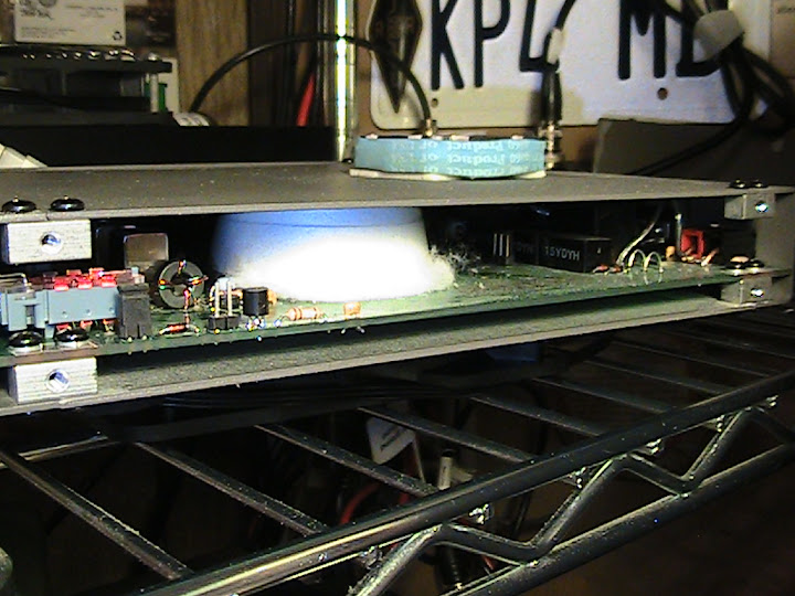
Some stations have added Styrofoam insulation, in the form of sheets or “peanuts” around a TCXO in order to reduce these short term variations. In at least one instance, an entire TCXO was outboarded, wrapped in plastic insulation and leads brought back into the radio.
Accuracy
Frequency accuracy isn't generally as critical to VHF+ WSPR operation since, as long as an accuracy problem is detected, it can usually be manually or automatically corrected. This is the function of the A/B settings in the stock WSPR code and described in the WSPR documentation. The goal of these corrections is just to “detune” the radio to correct for its internal frequency errors. These errors may be of two kinds, offset or scale.
The A term serves to bump the frequency on every band a constant amount to correct for a radio system local oscillator which has constant error versus output frequency or band. For older radios, this could include BFOs, carrier oscillators and even 2nd or 3rd conversion oscillators.
Newer radios and multi-band/multi-function radios increasingly use a single master oscillator which, with the help of DDS, PLLs, multiplying, dividing completely determine the output frequency,and perhaps even output phase. Absolute frequency error in this oscillator therefore contributes an error in the output directly related to it's accuracy, measured in ppm, ppb or percent. A master oscillator with a 1 ppm (part per million) error will produce a hamband output signal with 1 ppm error. On 2 m this would mean 144 Hz of dial error. The B term in the WSPR frequency correction code is used to calculate the amount of error for a given band and to “detune” the radio to compensate. Radios with single master oscillators that control everything will only need a B value entered since there are no offset oscillators the A value will always be zero.
Although accuracy errors don't usually prevent 2 M WSPR operation, they can spoil a radio for gathering significant propagation information. Actually this is true of HF as well. If it is known in advance that all frequency errors, within sufficient resolution, are due to the propagation path rather than the hardware at one or both ends, we start to learn more about radio science. At HF, for example, it is possible to measure movement of the ionosphere as the bands open and close. The change in height causes a changing path length which results in measurable frequency offset on a WSPR spot. Particularly on 20 m – 10 m, one or even two Hz of offset can be directly observed.
At 2 m and up, we begin to see some even more interesting effects if we have frequency accuracy. For one, it is much easier to identify individual stations on a busy waterfall where not all stations are decoding. But we even see situations where we get multiple spots, a “main” one and a Doppler shifted one, usually due to aircraft motion changing the total path length between WSPR stations. If this change is constant enough over two minutes, and it occasionally is, then we can successfully decode a spot that came to the receiver only by aircraft scatter.
In this thread, perhaps we can begin to discuss our experiences and methods for improving both frequency stability and frequency activity with the variety of radios and transverters we are using. This could help other stations. In addition I hope to add some information about the external GPS disciplined phaselock system that some of us are working on and hope to make available before too long.
Glenn n6gn cm88ok
7 October 2012

K6PZB
------------------
How I used frequency stability and accuracy:
When I was recently on vacation in Hawaii, I took my
IC706MKIIG and ran WSPR. I wondered what frequency
I was transmitting on. Sure, I could see myself in the
wsprnet.org 'database' for 20 meters, but folks who heard
me reported all sorts of frequencies.
So I looked up some of those stations and found a few who
provided useful info on their WSPR station files. I quickly found
that K5XL, K9AN, W3CSW and K3GEN all had some kind of
frequency correction and I noticed that all were within 1Hz of the
same frequency. I don't often see that kind of accuracy one any
WSPR band.
(I also noticed that WA2YUN on Wake Island was always within
a couple of Hz)
Having some stations really 'on frequency' is like having an
ARRL FMT going on all the time. In addition, Glenn points out
several other features of accuracy.
I would like to see more WSPR stations telling us in more detail
what equipment they are using. I would especially like to to see
how some of the current 2m WSPR group has fixed drifty radios.
And of course the bigger question is why aren't radio makers building
in better stability--Flex does it on there bottom of the line radio so
it couldn't be too big a deal. Maybe we all need to ask for it!
John, K6PZB
Glenn Elmore
On the these pages: Injection & External Phase Lock for the IC-706, John K6PZB and I have documented the two techniques we are currently using to put stock Icom IC-706 MKIIG transceiver on 2 m and 432 MHz WSPR.
The first technique, direct injection of a 30 MHz external master clock signal takes an external 10 MHz reference - a 10 MHz oven controlled crystal oscillator (OCXO) is shown but a GPS-Disciplined 10 MHz oscillator or rubidium standard will work as well - triples and filters it at 30 MHz and injects it into the master oscillator section of the Icom transceiver. A DC bias is used to disable the normal on-board oscillator. Use with care, the technique can result in very accurate 160m to 70 cm operation of the transceiver and no degradation of spectral purity. It is important that no low level spurious signals be injected along with the 30 Mhz signal since this LO goes into every oscillator in the radio and degraded performance could result. This is the system currently in use at K6PZB.
The second method uses an external 10 MHz reference as above, OCXO, GSP disciplined or rubidium standard, as a phase reference but works by comparing its phase with a sample of the radio's native 30 MHz master clock and generating a correction voltage that steers the radio's oscillator to be phase synchronous with the external reference. This second method has less risk of injecting unwanted spectral components on the basic transceiver operation because only components close to the carrier, within the PLL loop bandwidth of the carrier can be altered. The loop filter automatically limits any damage from spurious signals that might otherwise be injected. This is the system presently used at N6GN.
The techniques are shown are applicable only to the IC706 with a 30.000 MHz master oscillator. Both techniques require that the amateur transceiver use only a single master oscillator in generating all signals. Earlier models from Icom, Kenwood, Yaesu and the others may have used a single oscillator to generate the 1st or even 1st and 2nd LOs, but would sometimes use a stand-alone crystal or crystals to generate the carrier oscillator, BFOs etc.
Fortunately for those of us interested in 2 m and up WSPR, the new commercial multi-band, multi-mode transceivers are increasingly using a single oscillator scheme. SDRs, such as those from Flex, may actually have an external 10 MHz master clock input. The IC706, IC7000, FT817, FT857 & FT897 appear to have a single oscillator. Because the actual frequency required for some of these may not be a simple multiple (or division) of 10 MHz the techniques shown above have to be modified.
The External PLL project that John, K6PZB and I are now prototyping uses a TI PLL chip capable of locking a wide range of crystal oscillators or VCOs over ~ 1 MHz to ~ 3 GHz. This means that not only should this new design be capable of making standard multi-mode, multi-band transceivers precisely accurate but it can also be used to lock transverters - such as the Elecraft - that might be in use.
I hope to follow this post with pictures and details of the prototype board, once we have it up and all running.
Glenn n6gn

Leigh VK2KRR
Glenn Elmore
It's similar but not identical. The GPS/DO and external lock will work
fine with the IC-910's 30.2 MHz master oscillator. That is, it's capable
of making it phase synchronous with the disciplined OCXO. However,
steering the IC-910, particularly if it has the high stability option,
is somewhat more difficult than for the IC-706 and, I think, IC-7000.
The ic706 has a voltage -> frequency circuit already present. The master
oscillator is trimmed/netted from a pot. This makes tuning it very easy.
However, the IC-910 does not have this feature. The oscillator is made
fairly stable but the means of netting it electronically isn't present.
This means that we have to find a way to coax the oscillator to tune
more than residual time&temperature errors tune it.
Bob, WA6M, loaned me his CR-293 high stability option for the IC-910
and, when I get time, I'm going to try to see what can be done to make
it a VCO that can be steered far enough by the external PLL.
The Yaesu high stability option for the FT897 (and I understand for the
newer 817/857 as well) has a similar problem. The very efforts the
manufacturers made to improve the oscillator turn out to make it more
difficult to lock it. Good is the enemy of best in these cases I guess.
Of course, we always have the option of building our own replacement
oscillator for these radios but that adds to the cost of the solution
and I hope we'll be able to avoid it.
73
Glenn n6gn
Leigh VK2KRR

KP4MD


The crystal is likely mounted on thin springy wires which are spot-welded inside to the lead frame. However, the quartz is probably not in an evacuated environment so there are two sources for eating, the leads (conduction) and the air inside the can (convection). The question is, which one is biggest and wins the battle.
If the board, chassis etc of the radio ran warmer than ambient but didn't change and if the ambient air temperature was constant then the crystal would eventually settle at some temperature between them. If the air inside the crystal is by far the dominant (lowest thermal resistance) path then blowing constant temperature air on it will result in stable crystal temperature. OTOH, if the leads provide the lowest thermal resistance, minimizing the changes of the radio may result in lower delta-T at the crystal.
My first guess is that coupling through the leads and case is the dominant source of heat flow, but it may not be. This would indicate maximum air through the PA. If it isn't, maximum constant-temperature air on the crystal case may work better.
Both KP4MD and K6PZB saw significant improvement in stability by cooling the transmitter better and with the addition of cotton to reduce coupling to ambient air. You can try it both ways to see what you find works better.
Glenn n6gnThe intent is to keep the crystal at room temperature.
The room temperature is relatively constant at about 72 degrees and rarely changes quickly.
A +- 4 Hz drift during a 110 second transmission can prevent a decode.
Otherwise, +- 100 Hz is OK.
I hope to set this up in a few days and will report results.On 06/27/2012 03:26 PM, Carol F. Milazzo, KP4MD/W6 wrote:Chuck, N0SSC stuffed his oscillator compartment with cotton to provide thermal stability. As Glenn suggests, the external fan will help stabilize the overall temperature of the radio during transmit-receive cycles. Blowing external air directly onto the oscillator circuit without insulation may render it more sensitive to short term changes in room temperature. What do you think, Glenn?
Jwatrous
--
You received this message because you are subscribed to the Google Groups "2 Meter WSPR" group.
To post to this group, send email to 2-mete...@googlegroups.com.
To unsubscribe from this group, send email to 2-meter-wspr...@googlegroups.com.
Visit this group at http://groups.google.com/group/2-meter-wspr?hl=en.
For more options, visit https://groups.google.com/groups/opt_out.

Joe Pankow
What do you think about sticking a heating element on the TCXO can
inside the Yaesus and maintaining it at a slightly higher-than-ambient
temperature? Yaesus are still exhibiting drift with ambient over
day/night cycles with the TCXO option, so maybe we could snap
something over it.
Would need to sniff the LO frequency but I could imagine some kind of
apparatus that fits over the can and does both. If we have a good
thermal connection from the heater to the can, then we wouldn't need a
lot of heat (some kind of insulation to block the "breeze" when the TX
fans come on...)
I suppose this might not get to sub 1-Hz accuracy...and would have a
relatively long time constant. Just thinking in between emergencies at
work.
Joe KJ6QBA
n6...@sonic.net
>
> What do you think about sticking a heating element on the TCXO can
> inside the Yaesus and maintaining it at a slightly higher-than-ambient
> temperature?
temp/frequency correction algorithm in it, there's no guarantee at all
that externally modifying the temperature will give a monotonic frequency
change. It might very well go up with temperature for a bit and then turn
around and go down or vice versa. It could also change from TXCO to TCXO.
That technique also has the problem that the time constants are so long
that it could only be operated with extremely low loop bandwidth.
I guess I'd choose to build my own VCXO to replace it before trying to do
it with an external heater.
Glenn n6gn
n6...@sonic.net
> That's what WW6D has done with his FT 897.
>
> Just a thought.
>
>
you'd have to build and remote the entire oscillator, not just the quartz.
This is why I was suggesting that "remoting" the quartz on the end of
maybe .5" lead extensions might greatly isolate it from the changing PCB
temperature without causing problems to the VHF oscillator circuit.
WW6D remoted the entire oscillator module - quartz & oscillator circuit.
Glenn n6gn

Bob W7PUA
Thanks Glenn and John for figuring out the 706MKII mods. I have a 706MKII and plan to add that, soon.
I just wanted to toss in a general comment that I believe supports that of W6SZ. There are many benefits from getting the frequency on at "GPS" levels:
* It lets one know which station is which. We could even coordinate the frequencies!
* Once set up, two stations don't drift into one another.
* All the 2-minute drift problems go away.
* The Doppler information is very useful for understanding the propagation medium(s). This can be big.
* It saves a bunch of time---you don't have to check your frequency.
* For frequencies above 2-m it keeps getting more of an issue.
Unfortunately it does take effort, but I do want to push the benefits of getting into the sub-Hz level, rather than just getting "the drift down."
The LO phase locking ability, such as was described for the 706, is a big step. Exactly what you lock it to initially is a detail, as long as there is provision to use it. Something like a surplus HP 10811 10 MHz oscillator, will hold sub-Hertz levels on 2-m for months. The 10811 can later be phase locked to GPS for use up into the highest frequencies.
The 116 MHz oscillators can usually be injection locked, which requires minimum modification to the transverter A number of high-overtone oscillators have been locked this way by W7SZ, KD7TS, W7LHL(sk) using the surplus PTS-160 (or similar) synthesizers running with external 10 MHz. The basic approach is to add a coax connector to the transverter LO area and put 51 ohms to ground. Then place a 1 or 2 pF cap to somewhere in the xtal oscillator circuit. Run a cable between the two boxes. Adjust the PTS-160 frequency (very close to 116 MHz) and power level for reliable lock. If the frequency is not exactly 116, remove the effect in the I-F radio. The "loop bandwidth" for the injection locking of the crystal oscillator is low, especially if the injection signal level is minimal. This translates into good filtering of spurs/noise on the injection signal.
Some of the DB6NT (Kuhne) and Down East products now have provision for external 10 MHz.
And on it goes, but the main point is that working in the direction of very high stability is very beneficial, not only for WSPR but for any weak signal work.
Thanks, again, Bob W7PUA
Glenn Elmore
We've made some progress on the external phaselock project for stabilizing and putting 2 m and up WSPR stations using common radios on frequency, referenced to the GPS constellation.
I've started a page showing progress of this project that you can have a look at if you like, External phase lock project update.
Glenn n6gn
KP4MD
Glenn Elmore
This is intended to show our present thinking about how to modify/use these radios with the external PLL we're building.
I've also put some Icom 706 CR-293 High Stability Oscillator here.
Glenn n6gn

Scott Avery
n6gn
I know it seems slow but we've made some further progress on the external PLL project and I've put some more description and pictures on External PLL project Pilot status
As you can see, the first pilot unit, a GPS10P, is now complete and working with the IC-706. The next step is to complete the on-board VCXO option, the GPS10V,
and test with Yaesu FT-8x7 series, Icom IC-910 transceivers and Elecraft transverter.
Glenn n6gn
Leigh VK2KRR

KC6KGE
n6gn
https://groups.google.com/d/msg/2-meter-wspr/phtiS53dztw/nNDaMENRi3wJ
If you haven't already, look at the waterfall of WA6M on WSPR-15 on 432.3. It's really pretty neat how dead-solid that trace is. It's three times higher in frequency and about 10 times finer frequency axis.
I think we are going to see some interesting things once we get several stations on. I don't know if we will still have spots between us when we try WSPR 15 on 2m but I think we're going to be able to confirm whether or not the regular spots we've been seeing are actually ACS or not. I do notice multiple spots of KC6KGE occasionally. Normally, there's the 'normal' relatively stable one and another 10-20 Hz away that often has considerable 'drift' on it. I think that one is ACS with just the right flight path to produce constant rate of change of net path length, but I'm not absolutely positive of any of this yet.
Still working on fine tuning the FT8x7 VCXO and hope to try it out shortly with WW6D's FT897D. That should be a pretty good stand-in for your FT857.
Glenn n6gn
Steven Hess
looked into it yet.
A good 432 Mhz antenna and feed line is a whole nother kettle of fish as well.
Steven
____________
Apply appropriate technology. Use what works without prejudice.
Steven L Hess ARS KC6KGE DM05gd22
Google Voice 661 769 6201 +SMS
openSUSE Linux 12.1 KDE 4.7.2
Known as FlameBait and The Sock Puppet of Doom.

Pamela J. Filicky
From: n6gn <n6...@sonic.net>
To: 2-mete...@googlegroups.com
Cc: n6...@sonic.net
Sent: Sat, February 9, 2013 9:14:17 PM
Subject: {2 Meter WSPR} Re: Frequency Stability & Accuracy for VHF+ WSPR
You received this message because you are subscribed to the Google Groups "2 Meter WSPR" group.
Glenn Elmore
I am pointed at about 140 on 432.300 dial so you might see me if things are working properly. Neither of us is presently running WSPR-15 and unless you have a stabilized system, I doubt you will be able to decode it anyway. Symbols are only a couple of tenths of Hz apart and last for about 5 seconds each.
Glenn
Pamela J. Filicky
From: Glenn Elmore <n6...@sonic.net>
To: Pamela J. Filicky <psfli...@att.net>
Cc: 2-mete...@googlegroups.com
Sent: Sun, February 10, 2013 4:23:18 PM
Subject: Re: {2 Meter WSPR} Re: Frequency Stability & Accuracy for VHF+ WSPR
KP4MD

KP4MD

KP4MD


n6gn

May 21, 2013
There's much more to be said but here is a brief update of the five GPS10P and GPS10V pilot unit status.
These units are SNs 101...105. All five units are complete with the exception of the 105 which is waiting to have the on-board VCXO modified for 116 MHz operation. I have the parts and only value changes should be necessary. WW6D has been using/testing both 101 and 102 which are GPS10V (Yaesu FT8x7). He currently is running 101 which is why there are only four units, 102-105, in the photo. The scope is showing 10 MHz outputs from two of the units which are running entirely independently with different antennas, power supplies etc. These two have been warming up for a couple of days and the relative drift of the traces shows better than .1 ppb agreement. GPS_MonTrol, the VE2ZAZ tool for examining the GPSDO agrees that they are operating well.
In addition the unit one from the left, SN 102 a GPS10V for KC6KGE's Yaesu FT857, has a ~ 2v p-p 22.625000 MHz output cable and interface board attached. This is ready to plug into his radio once I ship the unit, PS, antenna and extension cable to him later today.
SN103,SN104 are IC7000 units which were completely working on my IC706 and which will lock up Bob, WA6M's IC7000 which I've borrowed, but they still have a funny with loop behavior which I'm chasing down.
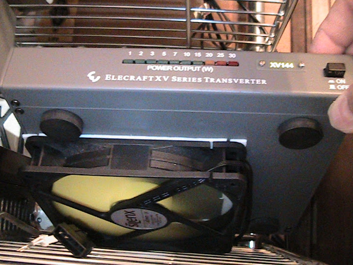
SN105 is the remaining GPS10V which will be used to provide 10 MHz reference for the SDR at KP4MD along with the 116.000 MHz output for Carol's Elecraft XV144 transverter.
Once all five of these are deployed, I will probably make another PC board turn to fix a couple of minor problems. Then *maybe* we'll still have strength enough to build up a few more units. At present, I don't even have one for myself and John, K6PZB, is using the prototype which is getting a bit funky.
I have no new insight as to how to get a large quantity of these made so that labor and parts cost come out of the stratosphere but we're pretty tired of handcrafting these already.
Glenn n6gn
Steven Hess
--
You received this message because you are subscribed to the Google Groups "2 Meter WSPR" group.
To unsubscribe from this group and stop receiving emails from it, send an email to 2-meter-wspr...@googlegroups.com.
To post to this group, send email to 2-mete...@googlegroups.com.
Visit this group at http://groups.google.com/group/2-meter-wspr?hl=en.
For more options, visit https://groups.google.com/groups/opt_out.
Apply appropriate technology. Use what works without prejudice.
Steven L Hess ARS KC6KGE DM05gd22
Google Voice 661 769 6201 +SMS
Leigh Rainbird
Leigh VK2KRR
Date: Thu, 23 May 2013 13:02:35 -0700
From: n6...@sonic.net
To: 2-mete...@googlegroups.com
CC: n6...@sonic.net
Subject: {2 Meter WSPR} Re: Frequency Stability & Accuracy for VHF+ WSPR
KP4MD


Glenn Elmore
Nice correlation! You may remember me telling Joe, K1JT, that I could tell the temperature in his shack from his transmissions on HF. It looks like your 'thermometer' is just as good. If these slopes don't drop to zero once the GPS10V is running something is very wrong!
Glenn
The preliminary data reveal a frequency variation of 50 Hz that correlates with the 75-85° F XV144 case temperature range measured over each 24 hour period. The frequency drift persists at a mean -3 Hz over each 2 minute WSPR transmission at 5 watts. This may be the best frequency stability that the Elecraft XV144 transverter can achieve with its internal 116 MHz local oscillator. The measuring station N6GN has a GPS disciplined frequency reference.
KP4MD
Steven Hess
While watching the WSPR waterfall tonight I noticed many KI6STW traces that I was not decoding. I realized that most successful KI6STW decodes occur immediately after one of my own transmissions. Curiously, both KI6STW and I have a mean -3 frequency drift during our WSPR transmissions, but my decodes of KI6STW show a drift that varies between -1 and +1 Hz, apparently my rebound frequency rise after each transmission period the KI6STW's frequency drop.
--
You received this message because you are subscribed to the Google Groups "2 Meter WSPR" group.
To unsubscribe from this group and stop receiving emails from it, send an email to 2-meter-wspr...@googlegroups.com.
To post to this group, send email to 2-mete...@googlegroups.com.
Visit this group at http://groups.google.com/group/2-meter-wspr?hl=en.
For more options, visit https://groups.google.com/groups/opt_out.
Steven Hess
> --
> You received this message because you are subscribed to the Google Groups "2 Meter WSPR" group.
> To unsubscribe from this group and stop receiving emails from it, send an email to 2-meter-wspr...@googlegroups.com.
> To post to this group, send email to 2-mete...@googlegroups.com.
> Visit this group at http://groups.google.com/group/2-meter-wspr?hl=en.
> For more options, visit https://groups.google.com/groups/opt_out.
>
>
In service.
n6gn


I think the two GPS10P/IC7000 units are ready to go. These are SN103 and SN104. The IC7000 required phaselock of its 124.032000 MHz master oscillator. Against a 10 MHz derived reference OCXO, this pushed the divide number to 7752 and produced a very low, 16 kHz reference. As a result of this large attenuation, I had to change loop architecture and values a bit but I think they are ready to put on the air. Hopefully Bob will have SN103 on at WA6M/2 shortly and KI6STW SN104 not too much later.
Here are photos and a screen shot of SN103 locking Bob's IC7000 along with WSPR-X and the GPS_MonTrol screens. The Mon_Trol program can be seen connected to one of the two RS232 ports on the GPS10 and is showing parts in 10^10 accuracy. It had only been running for a little while when this was taken and I think once settled in, perhaps after a week or more, performance in the .1 ppb area may be typical for it. These are just eBay OCXOs which are, I think, pulls from cell sites and not necessarily terribly good. But at only $10-$15 they seem a good choice. Even so, .1 ppb at 2m is probably better than the .02 Hz digital resolution of capability of the IC7000 and certainly better than anything WSPR can presently report.
Glenn n6gn
Steven Hess
Is this expected behavior?
Glenn Elmore
the counted OCXO frequency greater than an internally set threshold. The
usual reason for this is loss of satellite fix. Unplugging the active
antenna or shielding the antenna might do it. WW6D saw this occasionally
until he moved the antenna to a better location.
Another reason, less likely, is that the OCXO itself took a large jump.
This does happen occasionally but with reduced likelihood the longer the
OCXO has been continuously running.
Glenn n6gn
> You received this message because you are subscribed to the Google
> Groups "2 Meter WSPR" group.
> To unsubscribe from this group and stop receiving emails from it, send
> an email to 2-meter-wspr...@googlegroups.com.
> To post to this group, send email to 2-mete...@googlegroups.com.
Steven Hess
That means that it found the difference between the 1 PPS GPS signal and the counted OCXO frequency greater than an internally set threshold. The usual reason for this is loss of satellite fix. Unplugging the active antenna or shielding the antenna might do it. WW6D saw this occasionally until he moved the antenna to a better location.
Another reason, less likely, is that the OCXO itself took a large jump. This does happen occasionally but with reduced likelihood the longer the OCXO has been continuously running.
Glenn n6gn
On 06/21/2013 08:12 AM, Steven Hess wrote:
My GPS10V just went briefly into the a red flashing OCXO LED mode and returned to Green. This is the first time I have noted this so I thought I should mention it.
Is this expected behavior?
Steven
--
____________
Apply appropriate technology. Use what works without prejudice.
Steven L Hess ARS KC6KGE DM05gd22
Google Voice 661 769 6201 +SMS
openSUSE Linux 12.2 KDE 4.8.5
Known as FlameBait and The Sock Puppet of Doom.
--
You received this message because you are subscribed to the Google Groups "2 Meter WSPR" group.
To unsubscribe from this group and stop receiving emails from it, send an email to 2-meter-wspr+unsubscribe@googlegroups.com.
Visit this group at http://groups.google.com/group/2-meter-wspr.
--
You received this message because you are subscribed to the Google Groups "2 Meter WSPR" group.
To unsubscribe from this group and stop receiving emails from it, send an email to 2-meter-wspr+unsubscribe@googlegroups.com.
Visit this group at http://groups.google.com/group/2-meter-wspr.
n6gn
I think I'm almost done with the 1st five GPS10 units. The last one, a GPS10V/XV144 for Carol's Elecraft XV144 transverter 116 MHz LO replacement and 10 MHz for SDR reference is once again running. I had a minor disaster just as I was putting the final screws in the lid yesterday which caused me a great deal of grief and ended up with me replacing the PIC and reprogramming it. However, that is now running and the 10 Hz sideband fix seems to be doing the job pretty well. It is possible that there is still a remnant but it is right at the level of the phase noise of my IC706 at 80m (the IF when I'm downconverting the 12th harmonic of a clean 10 MHz with the 116 MHz LO in order to examine the LO purity). The GPS antenna-present LED seems to not be working but hopefully I can figure out and repair that without breaking anything else, as I did yesterday! I will be glad to have this final unit off the bench and deployed.
I also notice that my main frequency standard, a Motorala Oncore GPS receiver with PIC disciplining a Wenzel 10 MHz OCXO is off frequency. Consequently my recent WSPR spots should not be trusted. It turned out that with the rain we've been having in Northern California, the rain gutter was plugged and filled with water. The active GPS antenna had fallen into the gutter and became submerged. This caused it to stop working. Like the RoyalTek GPS receivers in the GPS10s, the Motorola receiver also continues to put out a 1 pps pulse even after it loses fix. This meant that the PIC started steering the 10 MHz reference off into the "weeds" since the unvalidated reference in the Oncore isn't very good. I finally noticed it when the OCXO would not steer any further off and the UNLOCKED LED came on.
This problem of GPS receivers putting out a 1 pps signal, supposedly correct, even when there is no valid fix is a weakness of the present approach. I wish that there were an easy way to qualify the 1 pps signal so that it only occurred when there was a valid satellite fix but, although that information is present within the GPS receiver, there seems no easy way on either the Motorola or the RoyalTek (SiLabs chipset) receivers to cause this to happen. It would be necessary to read the NEMA sentences coming from the receiver, identify the validated/fixed condition and use that information to qualify the 1 pps signal. This is a lot of effort to keep a "lying" 1 pps line honest!
Unless this is done, this makes it particularly important to ensure that there is a good satellite fix when the GPSDO systems work. I suggest using an active antenna mounted as much in view of clear sky as possible. WW6D initially had his positioned with only a limited sky view and found that on occasion, the receiver would lose valid fix and his frequency would become in error just as mine did today.
I suppose a better solution would be to build the GPS receiver from scratch right into the GPS10 but the chipsets in small quantity are not cheap and this would push the parts cost up even higher than it is.
All to say, if you use one of the GPS10s, put the antenna in a good location and/or keep an eye on satellite quality or fix via the RS232 interface from time to time to assure everything is properly referenced.
Glenn n6gn

n3...@aol.com
From: n6gn <n6...@sonic.net>
To: 2-meter-wspr <2-mete...@googlegroups.com>
Cc: n6gn <n6...@sonic.net>
Sent: Tue, Jun 25, 2013 12:27 pm
Subject: {2 Meter WSPR} Re: Frequency Stability & Accuracy for VHF+ WSPR
You received this message because you are subscribed to the Google Groups "2 Meter WSPR" group.

Bo, OZ2M
My experience with RFI into the GPS-RX is that they are fairly robust. Here at home I can transmit 2 kW on 2 m without any problems. A the OZ7IGY VUSHF beacons site http://rudius.net/oz7igy all the new Next Generation Beacons http://rudius.net/oz2m/ngnb/ are GPS locked from the GPSDO. Despite multiple carriers from 28 MHz to 24 GHz, yet all below 25 W, we have not experienced any GPS problems at all related to RFI.
I know that Thomas, OZ2CPU, uses a BPF on his GPS-RX in his radio controlled airplanes 2,4 GHz video link: http://www.webx.dk/rc/video-wireless/filtergps.htm But in his application the GPS and video antennas are very close.
So if there is a problem either filter the GPS input or provide some separation distance.
73
Bo, OZ2M
Steven Hess
n3...@aol.com
Glenn Elmore
Glenna n6gn
Bo, OZ2M
Indeed, quality doesn't come cheap. When we set out on the mission to design and build the Next Generations Beacons platform we wanted it to be better than a standard radio when it comes to frequency accuracy and phase noise performance. As can be seen the VCO is 40 dB better than the IC-202 which is a good radio when it comes to phase noise. Even with the low cost VCO the performance is 15 dB better or more. For us it has been important that nearby stations are not affected by the phase noise. It is possible to get an OCXO for less than 10 USD for sure but with a very different performance. On a flea market you can probably get one for even less. The OCXO in the GPSDO is about 150 USD.
Adding a band is about 350 USD.
Brian, WA1ZMS, is working on two beacons, 4 m and 2 m, from the US east cost using two of the DDS units and a VCO-PLL. I am not sure if you will be able to hear them, when they are QRV, despite being very high power as I guess most of you are on the US west coast?
73
Bo, OZ2M
Steven Hess
I can get the Flex-1500 connected to the GPS10V.
Any ideas?
Steven
> You received this message because you are subscribed to the Google Groups "2
> Meter WSPR" group.
> To unsubscribe from this group and stop receiving emails from it, send an
> email to 2-meter-wspr...@googlegroups.com.
> To post to this group, send email to 2-mete...@googlegroups.com.
> Visit this group at http://groups.google.com/group/2-meter-wspr.
> For more options, visit https://groups.google.com/groups/opt_out.
>
>
--
Glenn Elmore
The only MCX on the GPS10 is the GPS antenna connection. I don't think
you mean that one.
What you want is SMB to BNC. SMB isn't totally dissimilar to MCX but it
is larger and more rugged.
If you are making your own, which is the cheapest way, a connector for
RG174 is this one
http://www.digikey.com/product-detail/en/5414363-4/A32330-ND/813438
Adapters are more expensive, I didn't verify but I think this would work
http://www.digikey.com/product-detail/en/242185/ACX1386-ND/1012063
or I can send you something instead.
Glenn
n6gn
Steven Hess
for a few dollars.
> You received this message because you are subscribed to the Google Groups "2
> Meter WSPR" group.
> To unsubscribe from this group and stop receiving emails from it, send an
> email to 2-meter-wspr...@googlegroups.com.
> To post to this group, send email to 2-mete...@googlegroups.com.
> Visit this group at http://groups.google.com/group/2-meter-wspr.
> For more options, visit https://groups.google.com/groups/opt_out.
>
>
--
____________
Apply appropriate technology. Use what works without prejudice.
Steven L Hess ARS KC6KGE DM05gd22
Google Voice 661 769 6201 +SMS
Steven Hess
$500 delivered.
Don't know why I was thinking male.
Steven
Glenn Elmore
Not always obvious.
$500! what a deal. Was that $5 + $495 for hand delivery? :-)
Glenn

JG1KGS
KP4MD
- 16 July 2013 - At station KP4MD the GPS disciplined oscillator has been controlling the Elecraft XV144 transverter since 30 June, but the FLEX-1500 exciter continues on its own TCXO frequency reference. Spot reports of other GPSDO WSPR stations over 3 days suggest a diurnal 1 Hz frequency variation.
- Combining three days of WSPR spot reports of GPSDO WSPR stations KC6KGE on 144.490460 and KI6STW on 144.490470 MHz further emphasizes a diurnal 1 Hz variation in the KP4MD frequency reference. Also observed are clusters of spot reports of the other study group stations during specific times of the day when propagation appears to favor those signal paths.
- These data will be compared with observations made after connecting the FLEX-1500 to the GPS disciplined frequency reference.


KP4MD

Glenn Elmore
Looks good and like your exciter is now pretty much spot on.
I think the apparent "errors", such as on WA6M (2), KI6STW (2?), KC6KGE (18?) probably represent correct measurements of the received frequency caused by ACS Doppler shift in the path between the stations. I think all of these are likely transmitted correctly. That the longer path to KC6KGE has the bulk of the offsets fits my thinking as do those on KI6STW (at least) which, as received here, shows the large amount of aircraft activity over the three Bay Area airports. My waterfalls make it obvious why WSPR spots some of these as 'off'. Usually this happens when there is a larger crossing ACS component along with the "direct" component where WSPR gets confused. I think it likely that most of the KC6KGE spots are ACS but because of the long path length, the Doppler shift is less for suitable aircraft vectors.
When are we going to try 432 again and more? WA6M has suggested moving the tests to Wednesdays, which is fine with me. Anyone else?
Glenn
23 July 2013 - The Flex 1500 exciter at KP4MD was connected to the GPS disciplined frequency reference at 0330 UTC on 19 July 2013. The cumulative spot reports of GPSDO controlled 144 MHz WSPR study group stations since that time show resolution of the diurnal frequency variation that was previously observed while the Flex 1500 used its internal TCXO frequency reference. (N6KOG station frequency is not GPS disciplined).

dl.he...@gmail.com
Name is Dave, I am located in Hampton VA, and have been active on 2m sideband and MS for the last couple of years. I have been trying to get some people on WSPR here in the east. I have been running tests on WSPR here, and broke out the old kenwood and a laptop to check the frequency stability of my IC-746pro. I was surprised at the amount of drift I saw, and of course the chirp at the beginning. So it looks like I need to do some work to get this thing stable before carrying out any real tests. This rig will ultimately also be an IF for some transverters in the future, and part of a portable EME station when I get things together. So it looks like I will be doing more research on locking the frequency on this. This area of Amateur radio is fairly new to me, so I have a lot to learn.
Keep up the good work
Dave
N6DLH
On Sunday, October 7, 2012 10:59:55 PM UTC-4, n6gn wrote:
Frequency Stability & Accuracy for VHF+ WSPR
I'm starting this thread to create a place to discuss issues related to getting amateur equipment stable enough to successfully decode and generate WSPR signals as well as to discuss the value and means for having high absolute frequency accuracy as well.
Stability
Almost all of us who have put our stations on 2 m (or above) WSPR have had to deal with getting sufficient stability to allow good operation. What would pass as acceptable drift on 20 m is ten times worth and unusable by 2 m. By 1296 MHz, the problem has escalated another order of magnitude.
Generally frequency stability can be measured a number of ways, drift in Hz or ppm per second, minute, hour, day, year etc. For our purposes the critical time frame is the 2 minute WSPR window. Unless end-end signals show up with frequency change less than 3-4 Hz within two minutes, the station may not be usable for WSPR.
At 144 MHz, 1 Hz drift amounts to 1 Hz/144e6 = which is 7 parts/billion and less than a millionth of one percent. This is a much smaller value than the specifications on even the best high-stability frequency references for Icom, Yaesu or Kenwood transceivers. Normally these specifications are not very detailed and may not tell the radio owner much about the stability in an interval as short as 2 minutes but they do give an indication of the problem.
We do have stations on 2 m WSPR that are successfully operating both Icom and Yaesu hardware with the high-stability timebase but it's not guaranteed that this will work. Some radios do pretty well and some are marginal or unusable. In addition to temperature drift, particularly due to the entire RF deck warming/cooling during transmit/receive, there may be voltage dependence of the TCXO. The Icom unit has a characteristic “chirp” during the first 10-20 seconds of transmit when used in IC746, IC910 and perhaps other radios. Cutting the 14 VDC connection to the TCXO and inserting a fixed 10V regulator can eliminate this problem.
Even with the TCXO voltage dependency solved, these commercial high-stability options tend to drift around over time. It's not uncommon to see a 2 m WSPR station drift as much as 50 Hz as the hamshack warms and cools during the day/night. Although this type of long-term drift doesn't hurt WSPR operation, there are sometimes shorter term ones left, from chassis heating usually, that still limit station effectiveness.
Some stations have added Styrofoam insulation, in the form of sheets or “peanuts” around a TCXO in order to reduce these short term variations. In at least one instance, an entire TCXO was outboarded, wrapped in plastic insulation and leads brought back into the radio.
Accuracy
Frequency accuracy isn't generally as critical to VHF+ WSPR operation since, as long as an accuracy problem is detected, it can usually be manually or automatically corrected. This is the function of the A/B settings in the stock WSPR code and described in the WSPR documentation. The goal of these corrections is just to “detune” the radio to correct for its internal frequency errors. These errors may be of two kinds, offset or scale.
The A term serves to bump the frequency on every band a constant amount to correct for a radio system local oscillator which has constant error versus output frequency or band. For older radios, this could include BFOs, carrier oscillators and even 2nd or 3rd conversion oscillators.
Newer radios and multi-band/multi-function radios increasingly use a single master oscillator which, with the help of DDS, PLLs, multiplying, dividing completely determine the output frequency,and perhaps even output phase. Absolute frequency error in this oscillator therefore contributes an error in the output directly related to it's accuracy, measured in ppm, ppb or percent. A master oscillator with a 1 ppm (part per million) error will produce a hamband output signal with 1 ppm error. On 2 m this would mean 144 Hz of dial error. The B term in the WSPR frequency correction code is used to calculate the amount of error for a given band and to “detune” the radio to compensate. Radios with single master oscillators that control everything will only need a B value entered since there are no offset oscillators the A value will always be zero.
Although accuracy errors don't usually prevent 2 M WSPR operation, they can spoil a radio for gathering significant propagation information. Actually this is true of HF as well. If it is known in advance that all frequency errors, within sufficient resolution, are due to the propagation path rather than the hardware at one or both ends, we start to learn more about radio science. At HF, for example, it is possible to measure movement of the ionosphere as the bands open and close. The change in height causes a changing path length which results in measurable frequency offset on a WSPR spot. Particularly on 20 m – 10 m, one or even two Hz of offset can be directly observed.
At 2 m and up, we begin to see some even more interesting effects if we have frequency accuracy. For one, it is much easier to identify individual stations on a busy waterfall where not all stations are decoding. But we even see situations where we get multiple spots, a “main” one and a Doppler shifted one, usually due to aircraft motion changing the total path length between WSPR stations. If this change is constant enough over two minutes, and it occasionally is, then we can successfully decode a spot that came to the receiver only by aircraft scatter.
In this thread, perhaps we can begin to discuss our experiences and methods for improving both frequency stability and frequency activity with the variety of radios and transverters we are using. This could help other stations. In addition I hope to add some information about the external GPS disciplined phaselock system that some of us are working on and hope to make available before too long.
Glenn n6gn cm88ok
7 October 2012
KP4MD

