dQdx and dFdx
79 views
Skip to first unread message

John Wang
May 7, 2022, 9:09:46 AM5/7/22
to xyce-users
Dear Xyce developers,
It would be much appreciated if you could take your time to answer the following questions that I have in regards to dQdx and dFdx matrices.
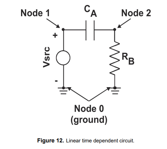
1. When I try to reproduce the dQdx and dFdx matrices from the circuit in Figure 12. on page 30 of your Xyce mathematical formulation 2.0 with the Xyce simulator, they do not correspond to the A and B matrices in equation 68. How could the correct Jacobian matrix be obtained with linear combination if the solution vectors of A and B do not correspond with each other? Only one of the matrices have the correct elements in the right places of the matrix, while the other one only contains the right elements, but in different/wrong positions.
2. Is there a way to reorder these dQdx and dFdx matrices so that the solution vectors correspond with each other?
I have already taken a look at the relevant functions such as, getBFSNodeList and generateBFT_. However, these code were too complicated to apply any changes.
Thank you in advance.
Regards,
John

xyce-users
May 9, 2022, 6:03:35 PM5/9/22
to xyce-users
Hello John,
I'm glad to help. I wrote that math document many, many years ago and I haven't looked at it much since then. It is always possible I made some mistakes (although I would hope not). In general, if I were to write a document like this again, there are some things I would do differently.
Looking at equations 67-69 the main thing that looks wrong to me is that 67 should have minus rather than a plus in front of the alpha*B*x^i term. For backward Euler alpha = 1/h, where h=time step, and dx/dt = (x^{i+1} - x^i)/h.
The solution vectors for A and B should have the same ordering, and only be different with respect to the time step index (i+1 vs. i). This is a linear circuit, so dFdx and dQdx should be constant, both with respect to time and with respect to the solution.
Another comment is that this section, 5.1, is written without any use of Newton's method. By default Xyce (and every circuit simulator) always use Newton's method, even if the circuit is linear. That will mean that Xyce doesn't solve equation 68 directly. But the two matrices (A=dFdx and B=dQdx) would be the same.
You can get the ordering of the variables and equations by using the "namesMap" capability, which you can invoke via command-line argument. Xyce -namesfile <path/to/file> netlist.cir, will result in a names file that is in the order of the solution variables. This ordering is also used by the DAE equations and matrices.
Also note that if you are outputting the dFdx and dQdx matrices, they are in a compressed row format. So, any entries that are known to always be zero will not be stored. As circuit matrices tend to be very sparse, this is often going to be most of the entries.
Also note that the matrices may have some artifacts for the DCOP solution, just to prevent singular matrices. Mostly, even though the capacitance currents are set to zero for the DCOP, the matrix entries are still nonzero just to avoid a solver error.
If I have misunderstood your question please let me know.
thanks,
The Xyce Team
xyce-users
May 9, 2022, 6:29:17 PM5/9/22
to xyce-users
Another question: are you looking at dFdx and dQdx inside the source code, or printing them to files? If you are looking at them inside the source code, where in the load/solve loop are you looking?
thanks,
The Xyce Team
John Wang
May 10, 2022, 9:23:45 AM5/10/22
to xyce-users
Hi,
Thank you for clarifying some of the questions that I had on the mathematical formulation book.
I am actually looking for the dQdx and dFdx inside the source code and have succeeded in printing them onto terminal either from NonlinearEquationLoader::loadJacobian() or obtainJacobian() by using the function .print(Xyce::dout()).
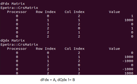
As per your suggestion, I also assumed dFdx and dQdx matrices to correspond to A and B matrices in equation 68/69 from the math document. However, only (dFdx = A), while (dQdx != B).
The interesting thing here is, depending on how I order the circuit elements in my .cir file, Xyce can produce either (dFdx != A) and (dQdx = B) or (dFdx!=A) and (dQdx!=B) . Please refer to the attachment below. Why does the order of circuit elements change the output of the matrices?
It would be great if you could let me know if there is a way to obtain the correct (dFdx=A) and (dQdx=B) matrices.
Thanks,
John
Thank you for clarifying some of the questions that I had on the mathematical formulation book.
I am actually looking for the dQdx and dFdx inside the source code and have succeeded in printing them onto terminal either from NonlinearEquationLoader::loadJacobian() or obtainJacobian() by using the function .print(Xyce::dout()).
As per your suggestion, I also assumed dFdx and dQdx matrices to correspond to A and B matrices in equation 68/69 from the math document. However, only (dFdx = A), while (dQdx != B).
The interesting thing here is, depending on how I order the circuit elements in my .cir file, Xyce can produce either (dFdx != A) and (dQdx = B) or (dFdx!=A) and (dQdx!=B) . Please refer to the attachment below. Why does the order of circuit elements change the output of the matrices?
It would be great if you could let me know if there is a way to obtain the correct (dFdx=A) and (dQdx=B) matrices.
Thanks,
John
xyce-users
May 10, 2022, 10:36:20 AM5/10/22
to xyce-users
Thanks for your reply.
The ordering Xyce used in your 3 example circuits is different than what is used in the document.
Your matrices (both dFdx and dQdx) look correct to me when I consider ordering being used by Xyce.
When I print out the names file from Xyce for your first circuit, (cir_1) I get:
HEADER
0 vcc_branch
1 2
2 1
0 vcc_branch
1 2
2 1
When I do the same for cir_2, I get:
HEADER
0 2
1 1
2 vcc_branch
0 2
1 1
2 vcc_branch
And for cir_3, I get:
HEADER
0 1
1 vcc_branch
2 2
0 1
1 vcc_branch
2 2
The math document assumes this order, which is different than any of the 3 examples:
HEADER
0 1
1 2
2 vcc_branch
0 1
1 2
2 vcc_branch
I get the same matrices from Xyce that you are getting, so we're getting the same ordering from Xyce.
thank you,
The Xyce team
John Wang
May 11, 2022, 11:09:01 AM5/11/22
to xyce-users
Dear Xyce team,
Thank you so much for the explanation. I apologise for not checking the solution vectors beforehand, I mistakenly assumed the order of solution vectors from Xyce to be the same as the one from the math document and that the order of these elements would be independent from the netlist structure. Is there actually a way to retrieve dQdx and dFdx matrices in terms of the ordering that I want?
I just have one last question that I would like to ask. I am currently interested in obtaining the B(t) vector described in line 405 from NonlinearEquationLoader::loadRHS() function. I know this term corresponds to the variable daeBVectorPtr. Since this variable is dependent on time, is it possible to retrieve the value of this variable for a specified time?
Regards,
John
John
xyce-users
May 11, 2022, 1:08:16 PM5/11/22
to xyce-users
Hi John,
The math document was written over 20 years ago, and the examples are intended to be generally illustrative and not 100% literally what Xyce would do. The target audience was applied mathematicians who are already very familiar with the numerical methods involved, but needed a quick explanation of the system of equations typically solved by circuit simulators. So, the document glosses over a lot of numerical details.
Also, Xyce has evolved a lot in 20 years. So even if the orderings matched the document perfectly in 2002 (unlikely), there have been many changes affecting the ordering over time. A lot of the initial orderings used by Xyce are driven by the parser, which continues to evolve. For example, the parser uses a lot of std::unordered_map objects, which was not the case 20 years ago.
Currently, there is no way (that I am aware of) to force Xyce to use a specific order. If you want the dFdx and dQdx matrices in a specific order you'll have to reorder them yourself as a post-process step. You can have Xyce output these matrices out to files and then import them into matlab, and reorder them there. Or you could do it in python, etc.
Note that once a linear system is handed of to a linear solver, that solver will reorder the system for various numerical reasons. If using a serial direct solver it will do this as part of its pivoting algorithm. If running with a parallel iterative solver, the parallel partitioning method chosen will result in reordering as well. Just to give two examples. But the outputs you have been looking at are upstream from the solvers.
Regarding the B-vector, the same sorts of outputs you've been using can also output the DAE vectors, including B.
To get a B-vector at specific times, you'll have to set breakpoints for those times in the netlist, to force the time integrator to land on those points. You can set this with the netlist command:
.OPTIONS TIMEINT BREAKPOINTS=0.2,0.25,0.5,0.75
Where the numbers on the right hand side are a comma-separate list of times you want the integrator to set a breakpoint. Usually these are used to handle discontinuities, but they can be set for any purpose you want.
Without setting them, the variable time stepping used by the integrator would not land on precisely the times you want, and you'd have to interpolate the output.
thanks,
The Xyce Team
Reply all
Reply to author
Forward
0 new messages