Coordinate system issue?

Jose Araujo
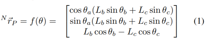
I was checking your equations in the CWoodenDevice.cpp file (which are in the paper as eq (1)) and tested in Matlab your equations by playing with the theta rotations and checking what was the movement in x, y and z.
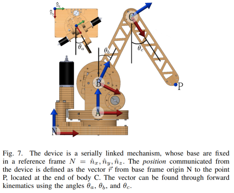
What I realized from my simulations is that your red axis in Fig 6 in the paper is z and x is blue (I could not find a definition for your axis colors in the paper but maybe I missed it). However, in Chai3D the axis is the other way around, where positive x is your red and positive z is your blue (http://www.chai3d.org/download/doc/html/chapter7-world.html). So when I test the woodenhaptics in the examples, the axis are swapped.
However, I have used the device previously and never really noticed this issue. Is this a problem coming from the new versions of Chai3D/OpenGL which somehow inverted the coordinate system or is there something else I am missing?

Jonas Forsslund
--
You received this message because you are subscribed to the Google Groups "WoodenHaptics users and developers" group.
To unsubscribe from this group and stop receiving emails from it, send an email to woodenhaptic...@googlegroups.com.
To post to this group, send email to wooden...@googlegroups.com.
To view this discussion on the web, visit https://groups.google.com/d/msgid/woodenhaptics/7b6e888e-cbef-4a99-be2e-8300ec74531e%40googlegroups.com.
For more options, visit https://groups.google.com/d/optout.
Jose Araujo
I was misinterpreting the results I was getting and I think I have a better understanding of this now. My conclusion on the flipped axis was not correct.
When you start the device, all the angles for each device (theta_a, theta_b and theta_c in the paper) should be zero? That is what is happening in my case and the initial position of the device is x=-0.02 and z = 0.205. If one plots the position (x,z) if only theta_c is modified and theta_a=theta_b=0, you see that the body rotates around a point approximately (x=-0.2,z=0.2), which implies that the initial position of the device is in quadrant IV instead of quadrant III which is what one expects given the pose of body c with respect to body b at the starting point. So basically for this to be correct, then the initial theta_c should be somewhere between -pi and -3*pi/2 and not be 0, so that the initial position is in quadrant III. Is this something that is being set or compensated in your code that is somehow not be enabled when I am running it now, or there is something very stupid I am missing? :)
What should normally happen is that when you start from the initial position,
if you move rotate body c upwards, z should be continuously increasing and x
should increase up to some point and then start decreasing (you move closer to
the user and then you start moving further away as you continue moving body c
upwards). However, by starting in quadrant IV when starting from the rest
position in my current case, the x moves closer to the user for a very short
period and then starts moving away from the user for most of the movement of
the body c, and in terms of the z position, it starts moving upwards for some
time but then when its still going up in reality, the reported z position will
start decreasing when you are still going upwards.
I am using the original parameters of the configuration file that you have here http://www.woodenhaptics.org/kit.html and implementing the equations you have in the CWoodenDevice.cpp.
Jose Araujo
Jose Araujo
I changed the equations in the file CWoodenDevice.cpp to calculated (x,y,z), so that it implements (1) in your new paper instead of the previous equations you had. Now it works as it should. However, the new equations give different results than the old ones, for example looking at the value for z, since now you use cos(theta_c) instead of sin(theta_c + theta_b), for the initial position where theta_c = theta_b = 0, then you are starting shifted 90 degrees, which now puts you in quadrant III instead of quadrant IV as before. Basically with the old equations you started with the body c 90 degrees forward, while now you actually start in the resting position because by using cos instead of sin we shift 90 degrees backwards. Hence it now works as it should. But as you wrote above, these equations should just be a simplification of the previous ones and should give the exact same results as the old ones, but they are actually different, or am I missing something?
Jonas Forsslund
--
You received this message because you are subscribed to the Google Groups "WoodenHaptics users and developers" group.
To unsubscribe from this group and stop receiving emails from it, send an email to woodenhaptic...@googlegroups.com.
To post to this group, send email to wooden...@googlegroups.com.
To view this discussion on the web, visit https://groups.google.com/d/msgid/woodenhaptics/62bef9ea-5c3b-475d-b756-c8f3894cdc77%40googlegroups.com.
Jose Araujo
I have not yet tested with the forces as I only needed to use it to get the positions at the moment :) But will try and let you know.
Jonas Forsslund
I am not sure I understand what you mean. If you look at the most simple case which is having theta_a and theta_b equal zero all the time, and just change theta_c, and check the value of the x and z positions with both the new and old equations, you can see that the two equations do not give the same result. So they are not equivalent right? You can check this quickly in Python, Matlab or Excel, setting theta_a = theta_b = 0 and vary theta_c, setting the parameters for the lengths as in the configuration file.
I have not yet tested with the forces as I only needed to use it to get the positions at the moment :) But will try and let you know.
--
You received this message because you are subscribed to the Google Groups "WoodenHaptics users and developers" group.
To unsubscribe from this group and stop receiving emails from it, send an email to woodenhaptics+unsubscribe@googlegroups.com.
To post to this group, send email to wooden...@googlegroups.com.
To view this discussion on the web, visit https://groups.google.com/d/msgid/woodenhaptics/59698c1e-7437-4e50-869c-a8800450c942%40googlegroups.com.