Encoder port addressing
53 views
Skip to first unread message

Charlie Peppler
Jul 23, 2020, 11:03:39 PM7/23/20
to vmx-pi
I am having trouble pulling data from a quadrature encoder (attached to this Pololu motor --> https://www.pololu.com/product/4757
I have read the kauai labs port documentation for wpilib mapping here --> https://pdocs.kauailabs.com/vmx-pi/software/vmx-pi-for-frc-2020-robot-programming/vmx-pi-for-frc-documentation/vmx-pi-io-map-for-frc/
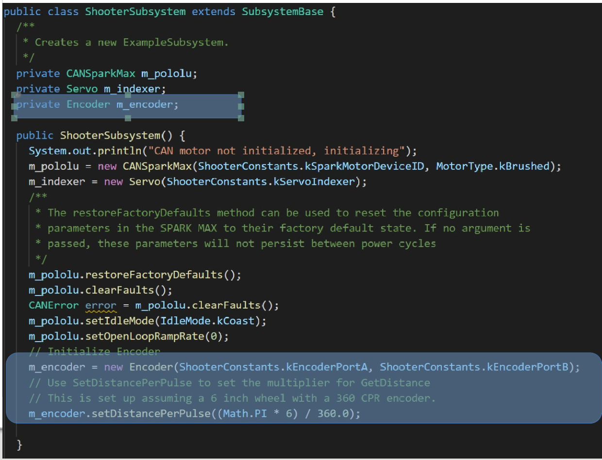
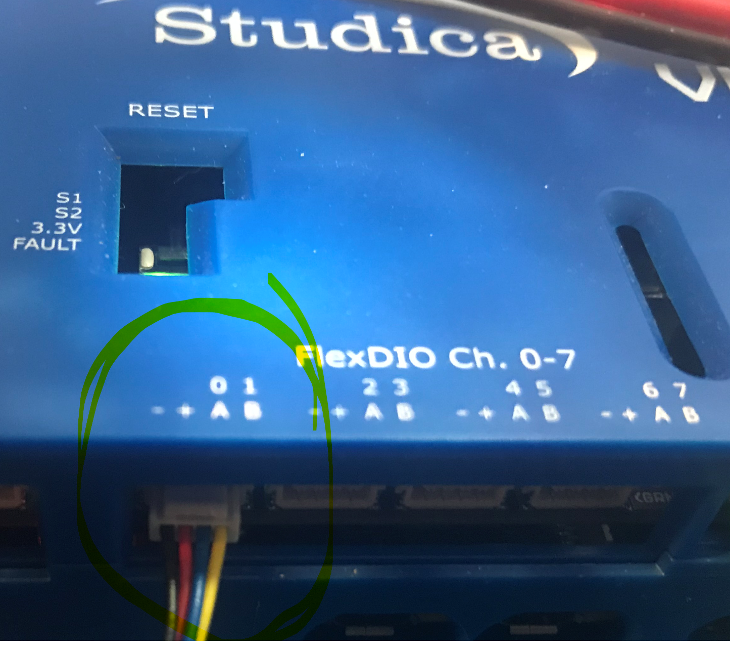
I am trying to collect input from the encoder from the first of the FlexDIO connectors as such:
From the documentation, I understood these to be addressed from the wpilib Encoder class
as such:
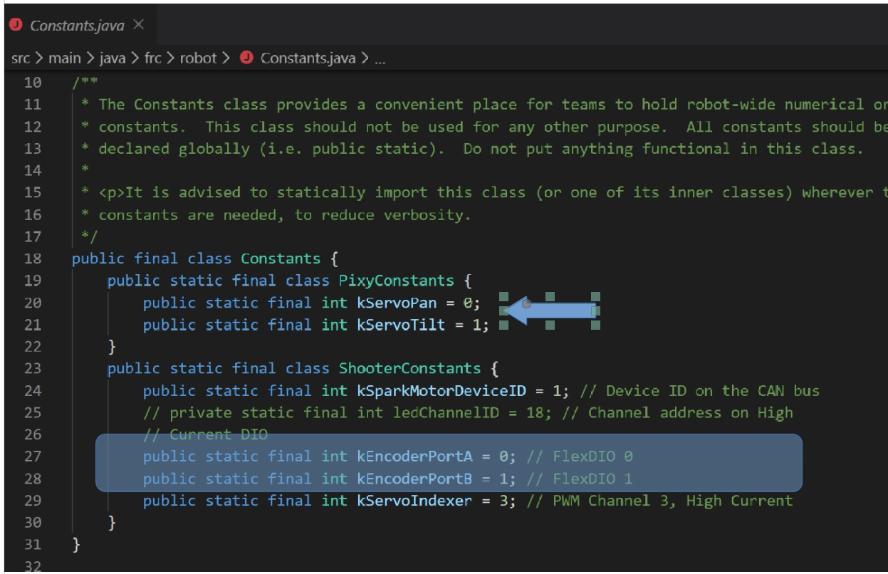
And then initialize the Encoder like this:
The problem is, the way I read the docs under Quadrature Encoder
Addressing, it the Encoder is addressed as 0,1 (A,B) (As Digital Inputs?)
but I appear to be getting a conflict/overlap with the PWM ports 0,1
Which address should I be using? Should it be the Flex DIO ports 0,1
or the PWM ports (although it says output only) 10 and 11?
I'm confused about how to correctly address the A&B inputs for the
Quadrature encoder.
Do I need to make some sort of WPILIB function call to let VMX-PI
Do I need to make some sort of WPILIB function call to let VMX-PI
HAL know what I'm doing with the FlexDIO ports?
Thanks for any guidance. You can provide.
Thanks for any guidance. You can provide.
Charlie

jrothr...@hdsd.org
Jul 24, 2020, 12:51:07 AM7/24/20
to vmx-pi
Charlie,
I actually have encoder code on the link I just reposted (for the Pixy code) as well.
Here is a snippet...
public class Robot extends TimedRobot {
private final Encoder leftEncoder = new Encoder(leftEncPortA, leftEncPortB);
...
...
@Override
public void robotPeriodic() {
leftSpeed = leftEncoder.getRate();
@Override
public void robotPeriodic() {
leftSpeed = leftEncoder.getRate();
SmartDashboard.putNumber("Left Speed", leftSpeed);
//Sorry, I have no idea how to do code formatting in Google Groups
I am using the same pins you are for the left encoder and am using High current DIO for the motor (PWM0). The full code is here. I also have a distance (I did not do any calibration so the units are not really inches, but encoder ticks) PID working here.
I am using vex encoders on this robot, but I also got the built-in encoders working with this base (working is a relative term, they are incredibly noisy and unreliable). This is not that great of an option (unless you want a really nice small robot platform. For the Vex Encoder, I made a cable by using a typical PWM Y cable, and cutting the ends off, and changing the one end to a 4 pin Molex which splits the power and ground line. Then I cut off the spliced signal line from one side and added the other signal line before putting 3pin Molex (or dupont, I forget which, and they are tucked in the belly of the drive base now) connectors on the two pigtails.
Message has been deleted
jrothr...@hdsd.org
Jul 24, 2020, 1:07:31 AM7/24/20
to vmx-pi
P.S.
Sorry, I just noticed I forgot the port numbers. Here are those lines.
private static final int leftEncPortA = 0;
private static final int leftEncPortB = 1;
private static final int leftEncPortB = 1;
As you can see, it looks as if they are implemented the same (though I am not using the command framework (or a robot Map class).
PPS. By "This is not a great option..." I meant that mecanum kit. It has horrible motors, but okay wheels. I am not familiar with the Polulu encoders, but they are similar to the mecanum kit motors. I wonder, if you commented out the servo code, do the encoders work as expected (They should regardless, the code looks good to me, but I could be missing something).
Reply all
Reply to author
Forward
0 new messages