uTracer goes WiFireless using ESP32 and webinterface
1,422 views
Skip to first unread message

Ihor
Jun 3, 2020, 3:43:25 PM6/3/20
to uTracer
Hi All,
Recently I was plying with ESP32 board (a rather cheap (5$) Arduino on 'steroids'), basically learning its possibilities and toying with it and I though that it would be nice to have it connected to uTracer and make it act as a webserver on a local LAN (or even independently as a WiFi Access Point) and do all the measurements (and possible more) via webinterface using a Mac or Linux laptop, ipad or mobile phone. After some attempts I put together such system, which is still highly experimental but it works good for my needs and I was wondering if someone would like to test it in the future or do something similar.
I do not have any manuals yet but most of the things are self explanatory. Briefly, I am using ESP32 (a very advanced Arduino like board, for those who are not familiar with it), which runs a webserver, hosts all the webpages, and then uses its GPIOs to connect to uTracer and send AT commands, exactly as the standard Windows software for uTracer does. The software on the ESP32 consists of C++ code and Javascript. The ESP32 can be connected directly to Tx/Rx pins of the PIC controller (of uTracer), or in my case, I use a small adapter (Tx/Rx to RS232), so no changes to uTracer are necessary and the whole system is modular and can be connected via the RS232 interface (just needs 5V power).
Right now the system can:
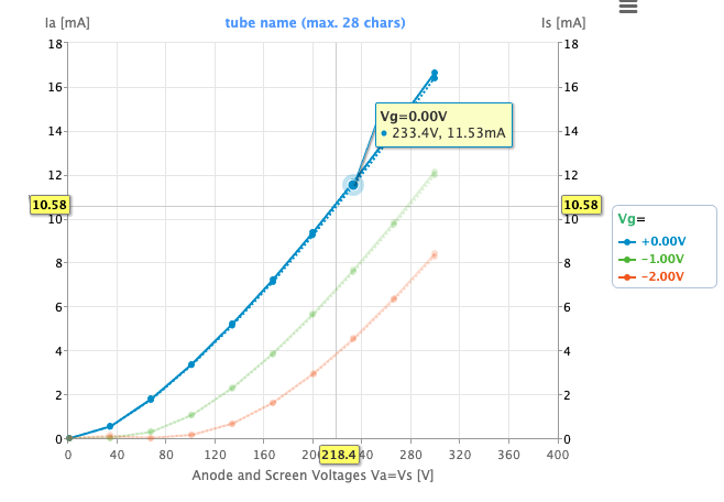
- acquire and visualize the measurements in a similar manner as uTracer's windows software
- save the measurements on its own flash memory, which can be later on downloaded or uploaded for analysis
- multiple curves can be loaded in the plot window (using so-called memory cells, it helped me a lot to match quads of tubes, looking at the curves simultaneously)
- plot interactive load lines and output all the parameters for that operation point as well as doing harmonic distortion analysis and so on
- model the acquired curves (either acquired by uTracer on the fly, or via uploading the previously collected .utd files) using most of the models that Derk described in his ExtracModel program. I found that program very useful but only windows based. I reimplemented (in javascript) only the models that I was planning to use (only triodes, pentodes and tetrodes, no fancy heptodes and so on).
I have some ideas for extra features, but most of them are based on what I typically do with the uTraces. It would be interesting to hear some ideas about possible additions, but it is a really hobby project, which is done over weekends (and not always).
I put all the webserver/javascript part of the code online and created a small website so anyone can upload their data and play a bit with the interface. It is located at http://utracer.live There, the 'Acquire' part of course does not work, but all the visualization, modeling and load-line plotting are functional.
I made a few screencasts to show how things look in practice.
- the data acquisition http://files.smal.ws/RfbGzC
- import of the utd files and plotting the load line: http://files.smal.ws/ib0ONu
- modeling of triodes and tetrodes: http://files.smal.ws/xnr5WN
You can go to http://utracer.live and try yourself. The photos of the ESP32 and the interface module are also attached.

Helmut Heller
Jun 3, 2020, 3:57:49 PM6/3/20
to utr...@googlegroups.com, Helmut Heller
Dear Henning,
This is so cool! I also own a µtracer and I use the ESP32 a lot (for other things: IoT). Are you willing to share your ESP programs? Maybe on github?
Congratulations, this looks awesome!!
Bye
Helmut
--
You received this message because you are subscribed to the Google Groups "uTracer" group.
To unsubscribe from this group and stop receiving emails from it, send an email to utracer+u...@googlegroups.com.
To view this discussion on the web visit https://groups.google.com/d/msgid/utracer/ffc7a09a-8d88-4904-b4a9-7eeb51aa110f%40googlegroups.com.
<ESP32uTracer.jpg><RS232uTracer.jpg>
Ihor
Jun 3, 2020, 4:25:08 PM6/3/20
to uTracer
Hi Helmut,
The initial plan was to put everything to github, and probably in the future I will do so. I might put the javascript quite quickly (even though those who know javascript also know that the code is already in their browsers and can be extracted without any problems). It was also my first experience with javascript in general, so the webpages are far from nice or stylish. I planned to check the CSS and so on in the end of the project :) or probably there will be some designer who would like to make the interface a bit nicer. For now the project is still in the state where things are tested to the very end, to work properly.
There is a small thing about sharing the C++ part. It implements the exact calibration procedure and values as used in the Windows software. For example utMax (alternative software for mac and linux) uses its own calibration values and I did not want to have that. It was not possible to get that part working just from the Ronald's logbook, so I contacted him and got some pieces of code in visual basic which I had to reprogram. As I understood, those are not to be shared online, so for now I will avoid that. Still, the C++ portion is also in the testing stage. Also, I am not sure how quickly the project on github will go out of hands.
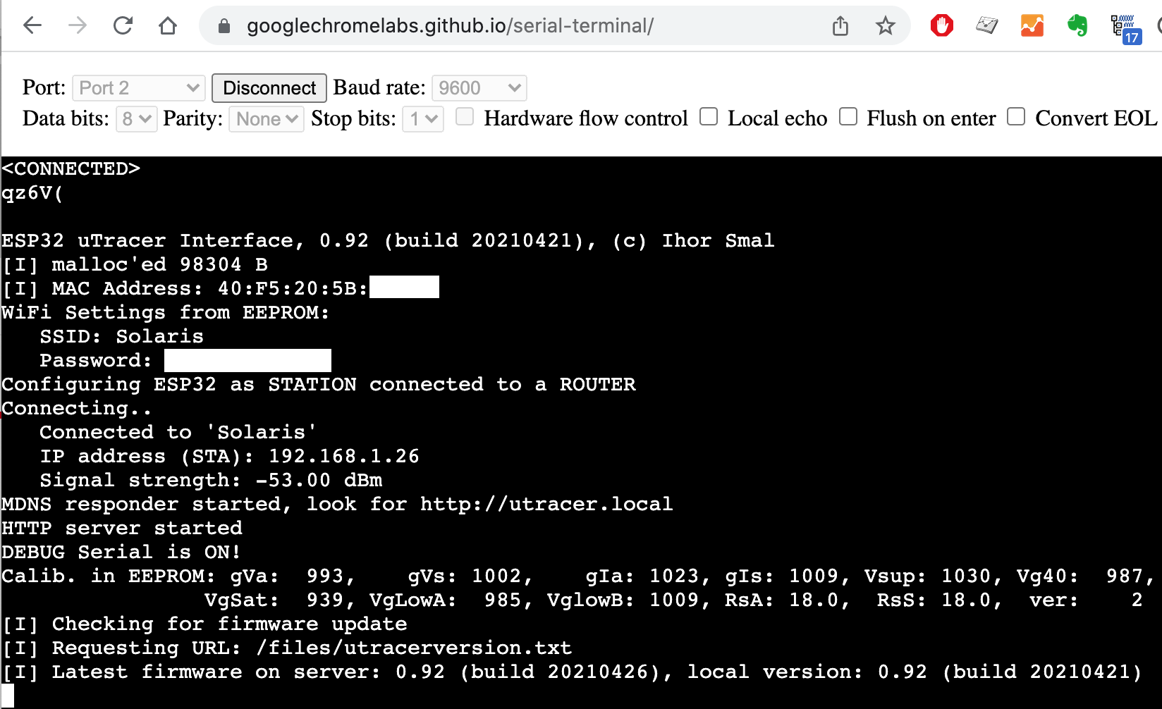
I can easily compile a binary that one can flash in their ESP32 and play a bit. For now I also have not spend much time on making any user interface for the webserver (WiFI login/password part). They should be written in the code and then compiled. I can make a small HotSpot interface that one has to connect to first and put the password to the wifi network or enter the password via serial interface of ESP32, using terminal connected over USB. Those things I have not explored yet.
So, for now I just wanted to share more of a progress than the finished product and probably get some extra input to implement some other useful things.
One more screencast about more technical details: http://files.smal.ws/3I8cCd
Cheers,
Ihor
Helmut
To unsubscribe from this group and stop receiving emails from it, send an email to utr...@googlegroups.com.

BHdeC
Jun 3, 2020, 9:32:31 PM6/3/20
to uTracer
Really impressive.
I was thinking at this the other day, but in a broader sense.
If we could get programmable high voltage and bias supplies, and with higher resolution DACs, interfaced to some Linux embedded system, then some could create an awesome generic tracer of about anything, web based so no proprietary UI code to maintain, and without proprietary API code as we would just use the discrete board's communication APIs.
Congrats on your work, especially with your first JS code :)
Ihor
Oct 10, 2020, 12:06:26 PM10/10/20
to uTracer
...small update with a fully functional version (hardware and software):
The whole thing connects to uTracer via RS232, so no modifications of uTracer is required. The interface works in any webbrowser, which means that you can use you computer, tablet or phone to perform full and quick tests, collect data, build loadlines and do THD analysis on your phone when you have 5 mins. of extra time :) The cost is about $2-4 for ESP32 and less than $1 for the TTL->RS232 module
As was mentioned previously, the software can be tested even without ESP32 module (so fully functional except it is not possible to acquire tube curves), just go online to http:/utracer.live or http://utracer.boffin.nl , upload your .utd files and have fun with building loadlines (now also for multiple paralleled tube configurations (PSE setups)).
Cheers,
Ihor

jgx plato
Oct 10, 2020, 2:41:19 PM10/10/20
to utr...@googlegroups.com
Hello Ihor excellent job! There is some web to find the software/hardware/how to, to conect my utracer to your app?
Again congratulations!!!
Jgxbos
--
You received this message because you are subscribed to the Google Groups "uTracer" group.
To unsubscribe from this group and stop receiving emails from it, send an email to utracer+u...@googlegroups.com.
To view this discussion on the web visit https://groups.google.com/d/msgid/utracer/33e7568b-39fe-47fa-bc41-a81f156644d9n%40googlegroups.com.
Ihor
Oct 14, 2020, 12:45:31 PM10/14/20
to uTracer
Hi Jgxbos,

For now I only put the software online, but that part of the software does not do the actually data acquisition but only data exploration and modeling. For the acquisition one needs to run that software on an actual ESP32 board.
The manual or instructions how to use it and connect everything are still in preparation but soon I will post them online (one just needs 3 parts and 7 wires). For now, everyone who already has a ESP32 board can test it, I can provide the instruction how to upload the code.
For those who are still interested in testing this module and do not have ESP32 yet, I ordered five ESP32 boards on aliexpress, as well as the required RS232 interface boards and connectors. When they arrive, I will flash them with the required firmware and can sell for the same price (should be around 5-6 euros) plus the shipping costs. In the latest version of the software/firmware it is possible to update the ESP32 with new (future) versions of firmware over the air, so no skills with, for example, Arduino IDE, firmware flashing and so on are required.
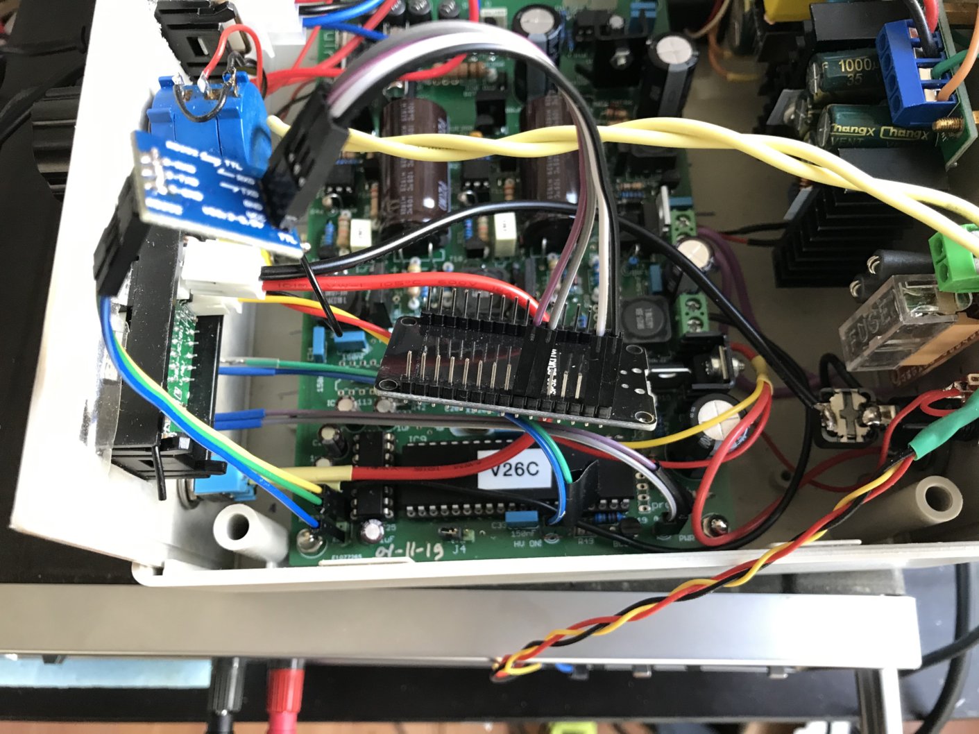
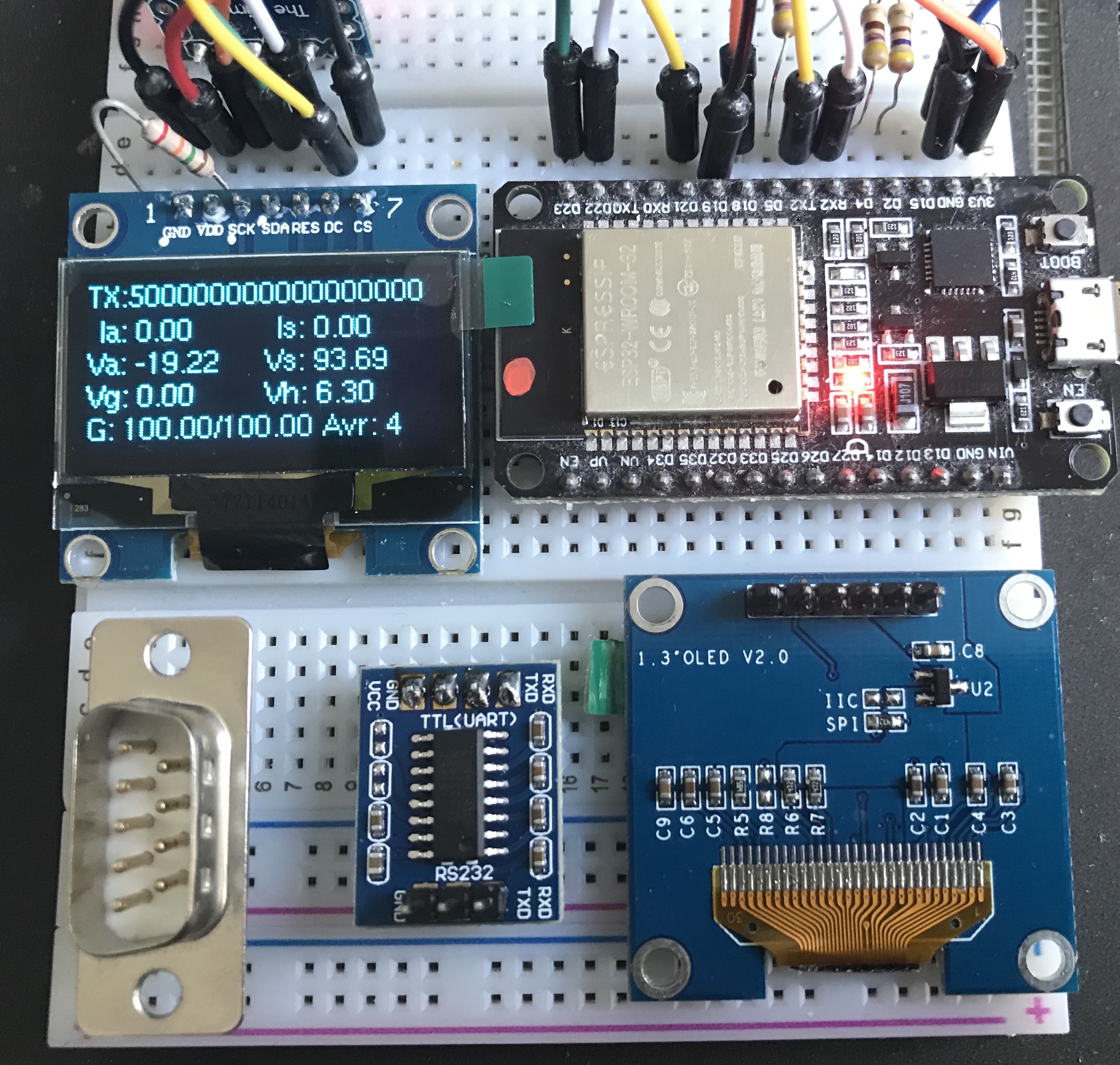
You can see 3 main parts that are necessary if one wants to connect the module externally through the RS232 interface of uTracer. It is also possible just to use ESP32 and connect directly to TX/RX pins of the PIC microcontroller (but you should be willing to do some simple work inside your uTracer. It is also possible to add some notification LEDs or OLED screen, but all the debug and log messages can also be seen on your computer if you connect to that ESP32 with a USB cable. One nice thing is that with this ESP32 module and the provided firmware you will still be able to run Ronald's windows based uTracer software, but now connecting now via COM-port but standard USB (the ESP32 will play a role of a proxy between PC's USB and uTracer's RS232).
Cheers,
Ihor
Ihor
Oct 14, 2020, 3:59:34 PM10/14/20
to uTracer
For those who are interested in experimenting with their own ESP32 boards, I started to write some kind of manual here: http://boffin.nl/wp/utracer-and-esp32/
It is still far from complete but I will try to update it regularly.
Cheers,
Ihor
jgx plato
Oct 14, 2020, 4:31:49 PM10/14/20
to utr...@googlegroups.com
Hello Ihor:
I have bought two ESP32, (ESP32-WROOM-32D and ESP32-WROOM-32U) from aliexpress, thought that I could flash the devices myself.
However if you sell the kit to connect the utracer, please book one for me.
Regards from Spain
Juan
To view this discussion on the web visit https://groups.google.com/d/msgid/utracer/23d42817-ccba-4992-94c8-f6f4679341cen%40googlegroups.com.
jgx plato
Oct 28, 2020, 6:39:41 AM10/28/20
to utr...@googlegroups.com
Hello Ihor,
The ESP32 have arrived from China. I have bought this ESP32:
I have bought this rs232 interface, too
Please could you provide me the files and instructions to flash the device in order to connect the utracer through your app?
Just in case, thanks for your excellent work!!!
Regards
Jgxbos
Ihor
Oct 28, 2020, 5:04:07 PM10/28/20
to uTracer
Hi Jgxbox,
Good to hear that you want to try. The manual is here, with all the required firmware and instructions. Let me know if they are clear and if everythign worked for you: http://boffin.nl/wp/utracer-and-esp32/
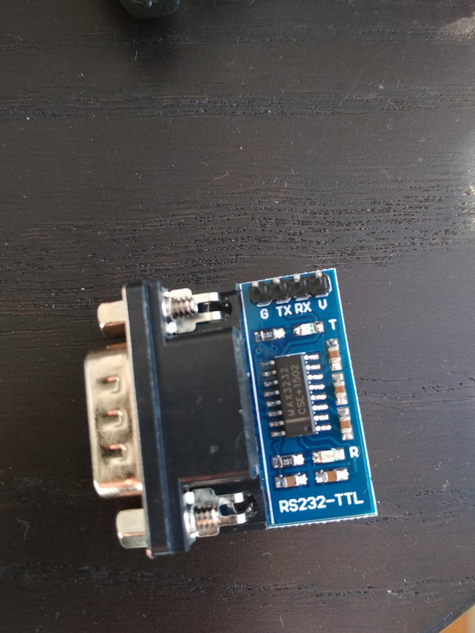
Two comments on your devices. You have 38-pin ESP32 and I show in the photo 32-pin model. It is not a big deal, you just have to use proper pins in terms of GPIO numbers (for TX RX and LEDs) and not the pin numbers based on counting them on the board.
The RS232 module that you mentioned is a Bluetooth to RS232 module, and for the combination that I showed bluetooth is not required. You need a TTL to RS232 convertor, see the photo on the website that I mentioned.
In any case, you can also send me an email if something does not work. I expect to get a bunch of proper convertors and 32-pin ESP32s in a week or so and then will do more tests and posts. Those will be available for purchasing.
Cheers,
Ihor
jgx plato
Oct 29, 2020, 3:15:10 AM10/29/20
to utr...@googlegroups.com
Thanks Ihor:
I have ordered a rs232 to TTL converter, this one
Next two weeks I will wait until I receive the converter, and after that I will begin the experiments.
Please, book one of your esp32 for me, just in case my hardware doesn’t work properly!
Thanks again
Keep in touch!
Jgxbos
To view this discussion on the web visit https://groups.google.com/d/msgid/utracer/10a57e70-d142-4335-99e5-07e0c4f0ccc4n%40googlegroups.com.
Ihor
Oct 31, 2020, 11:55:17 AM10/31/20
to uTracer
Hi All,
Small update, for those who might be interested in testing the ESP32 wifi module for uTracer. I finally got all the parts from the aliexpress, and can flash the ESP32 with the developed software and provide all the other small parts, so you can connect it right away and start testing. All the further updates are over-the-air so you will be able to do them in your browser without any cables.
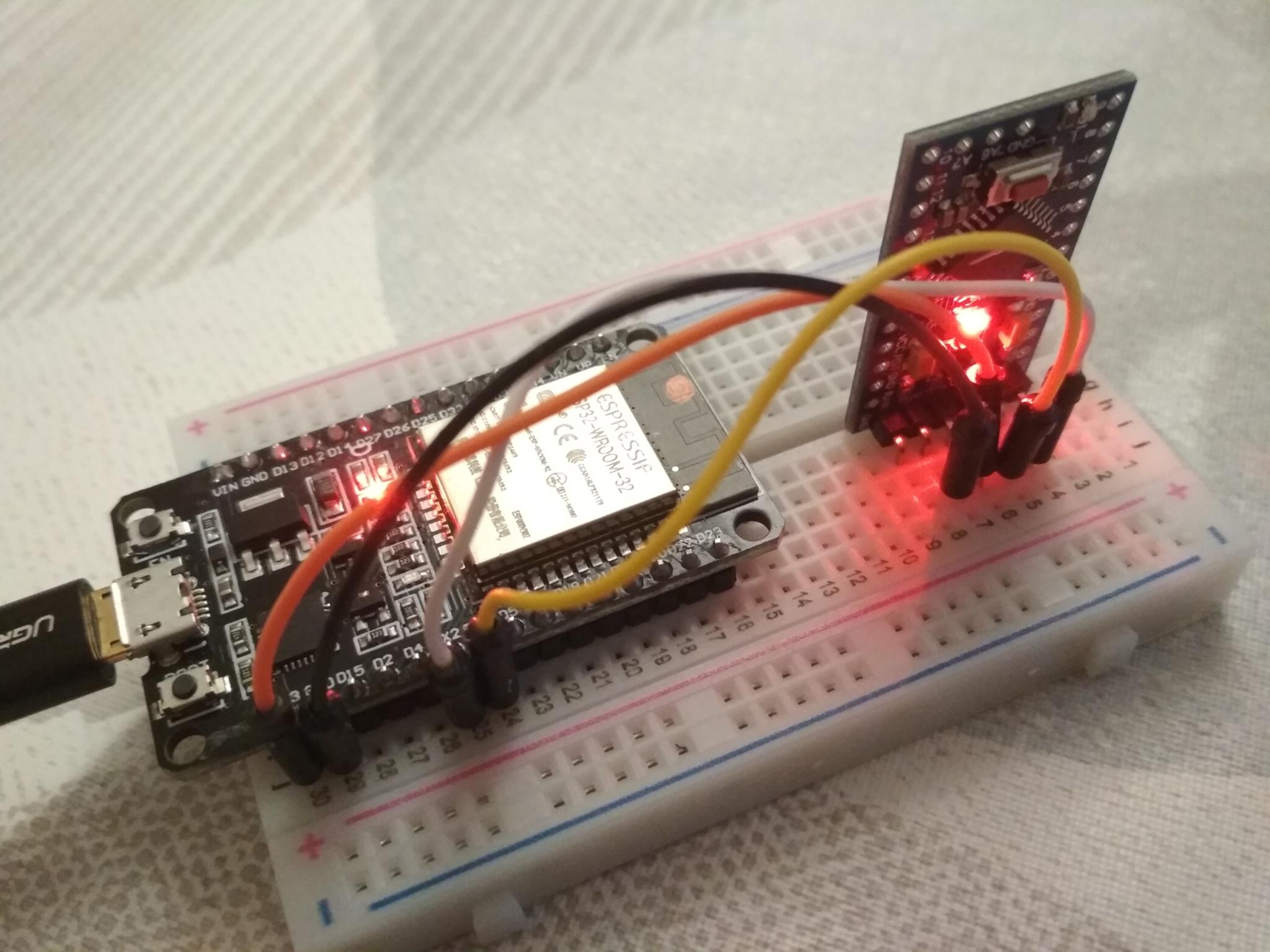
In the minimal configuration only 3 parts are necessary (see the photos):
- ESP32 module
- RS232 to TTL converter
- 7 wires
- (optionally) RS232 socket
All this essential parts I can send to you (any place in the world) for 10 euros, that also includes the shipping costs (which are basically half of the price of those parts). I will also add a few LEDs and resistors so you can have a some sort of visual debug, as in my other photos.
I also have those white breadboards where you can nicely place the ESP32 module and all the LEDs and play with it before you find a nicer case or decide to insert the module in the uTracer's case.
I only have 4-5 sets for now, but you can also order ESP32 and converters yourself somewhere online, and flash it according to simple instructions. Most likely it will not be cheaper but probably faster. For example it can take a month for an envelope to travel from Holland to the US. It is faster with European countries though.
All the instructions are still here: http://boffin.nl/wp/utracer-and-esp32/
Cheers,
Ihor
jgx plato
Oct 31, 2020, 6:04:30 PM10/31/20
to utr...@googlegroups.com
Hello Ihor, please book one kit for me!
The white board it is not necessary, I have a lot of protoboards!
Please let me know your PayPal in order to transfer the 10€ To you and I will let you know my address by a private mail.
Keep in touch!
Jgxbos
To view this discussion on the web visit https://groups.google.com/d/msgid/utracer/10d82649-cb25-49be-824c-1dc094e8a955n%40googlegroups.com.

Thomas Mayfield
Oct 31, 2020, 6:43:20 PM10/31/20
to utr...@googlegroups.com
Ihor:
Also please book me for one Kit with the White Board.
I'm at a US address and will be paying via PayPal.
I also will let you know my address by a private mail or via a PayPal message.
Thanks Ihor for all your hard work on this.
Tom Mayfield
Also please book me for one Kit with the White Board.
I'm at a US address and will be paying via PayPal.
I also will let you know my address by a private mail or via a PayPal message.
Thanks Ihor for all your hard work on this.
Tom Mayfield
"Never bite off more than you can chew, unless it’s Chocolate.”
To view this discussion on the web visit https://groups.google.com/d/msgid/utracer/CALFq-69J-A8mGUaTP6u_w7DpaFg0%3D7%3DTmEr8_WB3x4o8Crsq%3Dg%40mail.gmail.com.

Boban
Oct 31, 2020, 10:02:04 PM10/31/20
to utr...@googlegroups.com
Hi lhor,
if one kit with the white board is available, please add me. Once you confirm your paypal address via PM, I'll send you the money.
Thanks
Boban (Toronto, Canada)
To view this discussion on the web visit https://groups.google.com/d/msgid/utracer/MW3PR11MB47291C58666D00B144E16098AD120%40MW3PR11MB4729.namprd11.prod.outlook.com.
Ihor
Nov 1, 2020, 3:45:56 AM11/1/20
to uTracer
Hi All,
Thanks for your interest and your orders! By now I do not have those ESP32 modules anymore, all 5 are gone. I will contact you via email with my paypal details and will prepare the modules and send them during this coming week.
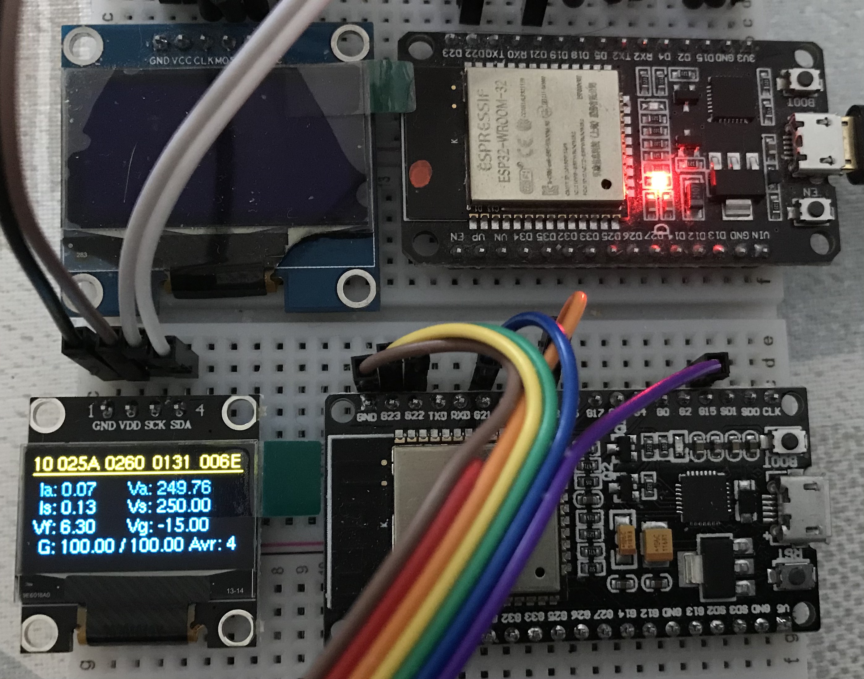
I can try to order more from aliexpress, but I am not sure if people like that way or like to order those parts themselves. This is also possible and might be even easier. The 'assembling' is nothing compared to soldering the uTracer. The flashing part of the ESP32 firmware is also easy, just following basic instructions. The only tricky part is that there are lots of different ESP32 variants (30 and 38 pins with 4, 8 or 16MB of memory, I used the simplest one 30pins and 4Mb, which is more than enough) and RS232 converters. In the photo below I showed what I used and what works and how it all connects. If you buy other variants you have to check yourself a bit which pins you have to connect. All the pins are still there, it is just the order is different. Also on those RS232 to TTL converters I saw that different manufacturers label TX and RX in a 'correct' or reverse order. The things that I used are all available on aliexpress or ebay. You can see how they look in the photo. I can also give you direct links on aliespress.
It is also possible to connect an OLED 1.3" screen which will show some debug info. For now I connected it and display some information but all that debug info is available in the serial monitor window on a PC screen and all the errors and progress is displayed with 3 LEDs as well, but probably in the future the screen could be used better (probably I will get some idea from beta-testers:).
Cheers,
Ihor

hans...@gmail.com
Nov 16, 2020, 2:43:40 AM11/16/20
to uTracer
Hi Ihor,
I just received Ronald's email. The plotting and analysis software looks amazing!
I've never done any Arduino programming but the flashing process looks straightforward so I've ordered ESP32 and RS232 modules from aliexpress.
Thanks very much for making your efforts available!
Regards, Dave.
Ihor
Nov 16, 2020, 3:11:46 AM11/16/20
to uTracer
Hi Dave,
Thanks! I am looking forward to your experiences! I would like to improve that software with the user's feedback and probably also implement some new features, but again that I would like to hear from the users.
One of the very far-fetched idea is to add a possibility to easily upload user acquired measurements to some common database online (because now uTracer is wireless:) ) and also to update you own database with tubes from some common database (for example for Quick Testing) , so users can easily share their data, or ask others to acquire for them of they do not have that specific tube in real life.
For those who are also interested in the module itself, this week I can again make 5 sets of the 'kit', which is just for those who do not want to spend time figuring out how to flash ESP32 and which boards to order on ebay or aliexpres.
For the same 10 euros I can send flashed ESP32, RS232TTL converter and RS232 connector including the wires, LEDS and resistors and worldwide shipping. For extra 1 euro I can send it with a white solder-less breadboard that you see in the images on the website, and for 3 euros more I can also add that 1.3" OLED screen. For now on the screen there is just all the debug voltage values during the acquisition and most importantly the IP address when ESP32 boots, so you see it immediately. Probably in the future I will add another information, but I am not sure which one is useful. As I mentioned previously, you can always order all those parts separately online, but by ordering part by part you might spend more on shipping from China than on the actual parts, so it is up to you.
Cheers,
Ihor

Felix Menendez
Nov 16, 2020, 11:17:00 AM11/16/20
to uTracer
Hi Ihor
I would like to order one of your kits (if still any available!). My location is 31007 Spain. Will be paying via PayPal.
Regards,
Félix

cdc...@gmail.com
Nov 16, 2020, 5:38:07 PM11/16/20
to uTracer
Hi Ihor,
I just received Ronalds email and was looking at your project. Congratulations, this looks FANTASTIC.
I have a few ESP32's kicking around and I will program one in the next few days and give it a try.
Excellent idea!!
Colin

piamp
Nov 20, 2020, 5:46:25 PM11/20/20
to uTracer
Hi Ilhor,
I just received my esp32 board, followed yout instructions, it works !!!!
I don't use serial on the utracer so i connected directly to the J4 jumper. a simple resistor divider to lower the 5V TX to 3.3V and it works !
Some questions and suggestions :
- when i connect the board to my wifi network, operation is VERY slow ; it is ok when i use it as the wifi host ?
- is there a way to save the presets when doing a full measurement ? i found it i, the quicktest feature but not the full measurement
- when testing a triode there's a nice feature in the utracer GUI that alows Ig scale to follow Ia scale (so the 2 scales are the same on the graphic and it's easy to compare both triode), i did not find it on your GUI ?
Anyway, NICE WORK !
Ihor
Nov 20, 2020, 6:13:25 PM11/20/20
to uTracer
HI!
I just received my esp32 board, followed yout instructions, it works !!!!I don't use serial on the utracer so i connected directly to the J4 jumper. a simple resistor divider to lower the 5V TX to 3.3V and it works !Some questions and suggestions :
Sounds great! Using the resistor divider is indeed a nice and simple solution which should work in this situation, no level shifting chips are actually necessary in this case. One just have to be handy with soldering and connecting things :)
- when i connect the board to my wifi network, operation is VERY slow ; it is ok when i use it as the wifi host ?
I would say that the problem might be with the distance to your wifi router. I have not experienced this kind of problems, even though in my case the wifi router is quite far (but not behind 3 walls, let's say). When you create a hot-spot, ESP32 is connected directly to your computer and the distance is pretty small. When it connects to a distant router, it might drop the speed. One option to check that it to see on the router (in the webinterface) what it is the connection speed with the router. Another, more practical approach is to move that ESP32 closer to a router (5-10m) and check if you get better speed. If that's the case, one of the easiest solutions is to get another EPS32 with external antenna (those are available online for the same price of 3-4$). I have not played with them yet, but the ESP32 chip is the same there and everything will work. In any case, let us know about your experiments!
Actually, when you start the measurement session and select to "Log to file", everything is happening on ESP32, which is connected physically to the uTracer, so even if the internet connection is dropped or you will close the page, ESP32 will finish acquisition and save everything to the file.
- is there a way to save the presets when doing a full measurement ? i found it i, the quicktest feature but not the full measurement
Indeed, there is no such possibility in the Full Test right now. I implemented it in Quick test, and still wanted to test it. I think in the future I will add such possibility, but I have to think about the logistic, how and where to put all that in the webinterface. I am also not sure that it will be compatible with Ronald's format, at least not back-compatible because there are also parameters those config files which are specific to the windows software. I was also thinking about the pin-numbers for some common tubes, to have reference pictures, etc, but that can also be hosted somewhere externally online and not on ESP32.
- when testing a triode there's a nice feature in the utracer GUI that alows Ig scale to follow Ia scale (so the 2 scales are the same on the graphic and it's easy to compare both triode), i did not find it on your GUI ?
This option is not implemented yet but it is easy to implement, so probably for the next update I will do that, locking Is axis to Ia, or just both axes at max of Ia or Is. Right now it is only possible to put both axes to desired Ia and Is values in "manual" mode.
Cheers,
Ihor
cdc...@gmail.com
Nov 20, 2020, 7:01:42 PM11/20/20
to uTracer
Hi Everyone
I had the exact same problem with the ESP being incredibly slow when connected to my WIFI. When running as an AP it was fine. I setup a separate wifi router right beside it just to test the distance issue and that was definitely the problem. When running as a client, but right beside the WIFI router, it worked almost as fast as when running as an AP. Perfectly usable. But when connected to my main WIFI, a couple of rooms away, it was completely unusable.
It's definitely an effect of distance from the router. The on-board PCB antenna on the ESP32 is quite limiting.
There are a number of hacks around to solder an external antenna to the ESP32. https://esp32.com/viewtopic.php?t=3770
I haven't tried it yet, but it looks pretty straight forward and I will be giving it a try in the near future.
There are also a few ESP boards that come with an external antenna connector already installed. I ordered a couple of of banggood. But they will take a month or two to show up.
When right beside the wifi router though, the software works as advertised and is really an amazing piece of work.
Great job Ihor!!!
Colin
Ihor
Nov 21, 2020, 3:31:14 AM11/21/20
to uTracer
Hi Colin,
Thanks again for kind words!
Indeed, small antenna can be a problem in some circumstances and apparently it was confirmed by you experiment. In my situation (apartment building, the distance between the router (Airport Extreme) and ESP32 and there are either 1 or 2 10cm-thick walls, depending on location) I have not experienced any problems. With more user experiences we soon will figure it out :) Probably, also when this module is places close to the uTracer PCB or in (metal) case, it is shielded to some extent, the WiFi strength also drops. I always use it via RS232 connection, so it is 10-20cm away from the uTracer and other power supply.
There are indeed ESP32 modules with external antennas, and they will work for sure (if those are based on ESP32-WROOM-.... module). There is also a ESP32-WROVER-IB module on expressif website which has 2 antenna options at the same time (build in and external). I will probably order this module and try, but on the website it also says that this module is getting obsolete and not recommended for the future developments. Out of the new generation modules on Exptessif, there is nothing with 2 antennas ( https://www.espressif.com/en/products/modules )
About the speed.... In my understanding the slowness can only be "experienced" with loading time of the webpages(?). The way ESP32 works is that it sends the webpage (tot he browser) for the QuickTest, for example, and then all the computations are done within the browser. If one starts some test, one sends a short request to the ESP32 over wifi, and then ESP32 does its job (no matter what the wifi speed is). When you observe the measurements arriving in the browser, they should arrive with the same speed (as in the case of ESP32 as an Access point or connected to the wifi router), because those are very short messages. Also the speed of acquisition (and what you see with arriving points on the plot) is defined by uTracer and not ESP32 or webinterafce. So, I would probably notice the speed difference only while jumping from one page to another, but not in any other functionality....
But hacking the antenna or getting the module with an antenna is the proper solution, even though for smaller distances in the house the standard ESP32 also works and, for example for me is preferable because then my utracer does not have any sticking antennas:) Also, if someone works in the basement (or some field work...) without internet connection, the "access point" mode of ESP32 will work just great.
Cheers,
Ihor
piamp
Nov 21, 2020, 5:03:29 AM11/21/20
to uTracer
Thanks for your answers !
Right now i'm testing again closer to my router and the speed is ok.
It also seems that using the IP rather than utracer.local helps (i'm on ubuntu)
Another nice-to-have feature : a "log" distribution of the plots, when tracing pentodes its very usefull
Some bug i have: aborting a measurement leads to unreponsible unit and a "restart utracer" message
About the pull up resistor : don't know if i need it when directly connected to the IC? Tried with and without it, seems to work the same
Ihor
Nov 21, 2020, 6:39:19 AM11/21/20
to uTracer
Just to answer quickly.
Right now i'm testing again closer to my router and the speed is ok.It also seems that using the IP rather than utracer.local helps (i'm on ubuntu)
Probably indeed it takes more effort to resolve that utracer.local within your WLan but that's good to know.
Another nice-to-have feature : a "log" distribution of the plots, when tracing pentodes its very useful
I saw that option in the windows software but I have never used it, so I have to check what kind of log it is, on X, Y or both axes. Comparing to the standard triode and pentode datasheets I have never seen logs, so was not bothered with that. I will see if it can be implemented just as an option that changes the view, of the plot or do you really want to acquire the .utd files with log'ed values? I did not considered that option because also later on you cannot model anything with such scaling. I will explore that option, but it would be good to know the advantages of usage for myself.
Some bug i have: aborting a measurement leads to unreponsible unit and a "restart utracer" message
That sounds strange, I have not noticed that (but I do connect through the RS232 interface). Without the pullup resistor from time to time I was getting very weird behavior of uTracer. You can start the terminal and see what's happening there while aborting, what command is send and what is received back, then we would know exactly what causes the problem. This kind of issues, if they are present I would like to fix, but to me it looks like it is more due the direct connection to the PIC. I will do some extreme testing myself today :)
About the pull up resistor : don't know if i need it when directly connected to the IC? Tried with and without it, seems to work the same
I have not looked into that, if PIC controller has pulled up RX line or not. That would be a separate thing, and I can assume that as in Arduino for example, those pullups are on the chip, so programmatically activated (or not) so it is difficult to check for me. I do lots of tests with an Arduino which I programmed to behave as a fake uTracer, and there are no pullups required (but also wiring is extremely short in this case).
Cheers,
Ihor
piamp
Nov 21, 2020, 7:40:27 AM11/21/20
to uTracer
The log thing is not a graphical representation : it's a log distribution off the measurements points
with a 6L6 for example when you graph Va as X and Ia as Y, Ia quickly raises for small V value and then is fairly horizontal
so when you take 10 measurements it's great to have more points when Va is small and then they can be more scarce.
That's a log distribution of the 10 points :)
but the graph scale is not logarithmic.
I hope i'm clear :)
About the terminal i'll do that !
thanks !
Ihor
Nov 22, 2020, 3:57:43 PM11/22/20
to uTracer
Just a small update. I put the new firmware on the website, so people can try to upgrade. I implemented "locking" of both Y-axes, what was asked by one of the user and the "Log" scale is on its way. Also saving the Setup parameters will be implemented in the end, but I am not sure how soon.
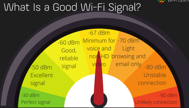
One of the important things, to deal with complains about the WiFi signal strength, with the new firmware, ESP32 will measure the strength of the signal and report it in the Serial terminal and on the OLED screen. So, it is good to collect some statistics what people are getting. In my case (2 10cm walls 7m from the router) my signal is -62dBm (see the image below with categories) and my internal antenna is doing pretty good. It looks like if you get less than -70dBm you might start thinking about ESP32 with the external antenna. The size of the files on the ESP32 is quite small so -70 ("light browsing") should still be oke.
piamp
Nov 24, 2020, 7:05:16 AM11/24/20
to uTracer
Great !!!
I did the update and Y lock works well ! Very handy to test 12AX7 :)
about wifi strengh: i get a very good speed when i use the ESP32 ip in the brower and not 'utracer.local', and my router is far away from the ESP32 (3 walls). So it seems quite good at picking up signal !
piamp
Nov 24, 2020, 10:46:17 AM11/24/20
to uTracer
small bug : choose "as Y2" AND "as Y1" and it crashes :) infinite loop!
also it would be nice to have round numbers on the Y axis (and not 2.34 for example)
Ihor
Nov 24, 2020, 11:57:22 AM11/24/20
to uTracer
small bug : choose "as Y2" AND "as Y1" and it crashes :) infinite loop!
I think you are trying to do it int he very beginning, when you see the "triode logo". That logo is not a real plot, so all the menu-selections for the plot are tricky, because there are no real curves, so no real values on the axes and so on:) So it is not a bug, it is a behavior that will be blocked in the future. Usually it is done when the all the other user-interface things are be finalized. In the end, when there will be no real acquired curves visible in the plot-window, all the drop-out menus will be blocked.
Another behavior which can be noticed, which is not a bug but thing that will be finalized later, is when you send the desired point shapes, line style and so on and then start doing measurements, those parameters will not be applied. Again, for now, one has to first acquire or load the curves and then start applying those decorations. In the future it will be changed as well.
also it would be nice to have round numbers on the Y axis (and not 2.34 for example)
Right now the min and max on Y-axes are rounded to 0.25 for mA range for example, so one gets nice numbers, like 10.25 or 76.50, but of course if the number of ticks is not a "nice" divider, one gets all those 12.333 in between. Rounding in this case is an (ugly) solution. In the windows software (in the "manual" mode) it is also the case. In "auto" the number of ticks is not computed automatically for now (also because it might lead to different numbers of ticks for slightly different ranges). In the Windows software, the number of ticks in "auto" is changing all the time during acquisitions to accommodate nice axis labels (like 10.25, 11.75) and so on. In the future I will see what can be done with that axis-labeling-function. For now, the best way to get the desired scaling is to switch to "manual" and find a good number for ticks.
Figuring out good tick placing algorithm is actually a nice problems that does not have one unique and the best solution...
See examples here:
Ihor
Nov 24, 2020, 2:50:32 PM11/24/20
to uTracer
On the main website I created a section with BETA software and put the latest version.
- Right now the mentioned bug when locking one Y-axis to another one and then the other one back to the first one is solved.
- I also implemented support for Ronald's .uts files that contain the configurations/setups (as was requested by one of the users). It can import the most important fields and even some parameters for plotting (which are also present in the ESP32 webinterface). There is no complete backward compatibility because ESP32 also uses other parameters. In the future version I will implement saving to the .uts as well, but that file will be shorter with only necessary fields.
- Also, the logarithmic scaling of the anode voltage is implemented (exactly as here https://github.com/colincci/pUtracer/ ) but I must say that it is not exactly how Ronald's windows software does it. It is pretty close but apparently the formulas are slightly different.
- The Heater section is moved to the "Home" menu, because now with loading of the config files, the heater should also be set up and it was not possible before. There is one nuance here. There is still an open question what to do when the heater is already ON (for example at 6.3V) and then one loads a config with let's say 12.6V setting for the heater. It is possible to stop the heater and then ask the user to switch it on. Automatically switching is dangerous because user might not know beforehand what is the heater voltage in the config file. It is also possible to alert the user only when the heater voltage changes. I am still not sure what to implement. Interestingly that Windows software ignores that possibility/option: after one sets the heater voltage to, for example, 6.3V and press "Heating" button, then one can do "Measure" at 6.3V, then load any other .uts with different heater voltage, and then after pressing "Measure" it will be still done with 6.3V. The software does not reinitialize the heater, one has to "Abort" and then "Heat" and "Measure".
Ihor
Nov 28, 2020, 6:35:54 AM11/28/20
to uTracer
Just an update that the new version of the firmware (0.7) for ESP webinterface is already on the website. The changelog is here: http://boffin.nl/files/firmware_changelog.txt
Thanks for the feedback and suggestions! Briefly, all the comments posted here were implemented: locking of the axes, Log-scale, loading and storing the configuration/setup files, also a far better axes labeling is implemented (so no more weird numbers like 1.324 and so on). Additionally, now all the options "track" for axes are implemented exactly as in Ronald's software.
Feel free to post your questions or suggestion here or via email!
Cheers,
Ihor
Message has been deleted
piamp
Nov 28, 2020, 7:27:24 AM11/28/20
to uTracer
Great !: Trying it right now!
would you explain what is "vg low" and "voltage correction?"
Ihor
Nov 28, 2020, 7:37:43 AM11/28/20
to uTracer
Ihor
Nov 28, 2020, 7:39:10 AM11/28/20
to uTracer
I am not sure why the text of the previous message has disappeared, here it is:
About the firmware, I forgot to update the title of that section, so in general there will be only the latest version and the beta version:)
vg low is fo the Grid Loupe (there is also a thread on it in this forum but also here : https://www.dos4ever.com/uTracerNotebook/Notebook.html#grid2
When you use that extension board, utracer still works with 0-50V grid voltages, which are translated to -10...+5 by the grid loupe. So, that to inform the software that we are using gridloupe.
Voltage correction is the parameter which is in Debug menu of the windows software. Basically, if one says that the anode voltages should be 100 150 200V, the utracer measurements will be slightly smaller (due to voltage drops on sensing resistors), so probably 99.65, 149.34 199.12 and so on. So with that voltage correction check box it is possible to say what you want to have in your acquired .utd file. The problem with exact voltages is that the legend will look weird and also if you do a sweep for Vg from lets say -10 to 0, with Va=100, then for each point of Vg, the value of Va will be slightly different, so again depends what you want to have in the .udt file after the acquisition.
I also just got those 0.96" OLEDs today and they are working with EPS32 without any problems. They are a bit smaller than 1.3" but the visual difference is quite noticeable. In any case, they are two times cheaper than 1.3" screens and at least can be used to diplay the acquired IP address or some debug or error/warning messages.
piamp
Nov 28, 2020, 2:05:26 PM11/28/20
to uTracer
thanks a lot !
i'll order a small screen on aliexpress, wich one would you recommend ?
piamp
Nov 28, 2020, 2:06:11 PM11/28/20
to uTracer
And the settings saving feature is WONDERFULL ! thank you !
Ihor
Nov 28, 2020, 2:21:59 PM11/28/20
to uTracer
Thanks!
Those 0.9" that I tested today are quite small I would say, so 1.3" OLED is a better choice. The difference in prices is something like 1.7euro vs. 2.80 euro. There are two versions on aliexpress or eBay: SPI (7 pins/wires) and I2C (4pins/wires, runs on a 400kHz bus). For those screens the SPI version in principle way faster than I2C (according to specs) but needs 7 wires to connect. At the same time, for that EPS32 and uTracer, one cannot see the difference between slow and fast screen because all the re-drawings and messages from uTracer are "slow". If we would output on the screen every transmitted byte between ESP32 and uTracer, that probably would matter, but I am not sure if that's a useful information to see:) So, you can choose any of those, if you do not mind having 7 wires vs 4, then SPI screen has a bit more potential (but I am not sure if that potential will ever be exploited).
The driver chip of the screen, which is supported, is called SH1106. You can either search for that key work on aliexpress and see the screens with 1.3" size.
Cheers,
Ihor
Ihor
Dec 3, 2020, 10:40:57 AM12/3/20
to uTracer
Another update, I just put a new Beta version for those who wants to try some small feature updates and also bug fixes. It is on the website in the Beta firmware section and the changelog is here: http://boffin.nl/files/firmware_changelog.txt
Most of the improvements are thanks to Tomas (from Sweden) who also created nice description of how that ESP32 uTracer webinterface can be used on other development boards, which use ESP32 module on board:
Cheers,
Ihor
Ihor
Dec 7, 2020, 11:01:12 AM12/7/20
to uTracer
As another quick update, I put the new beta version on the website, and from now on it is possible to make a backup of all your .utd and uts files and save it as a zip-file, and then, after firmware update, restore all those files back (from that zip file, either all of them, or selectively).
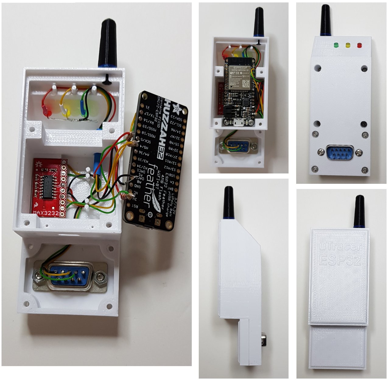
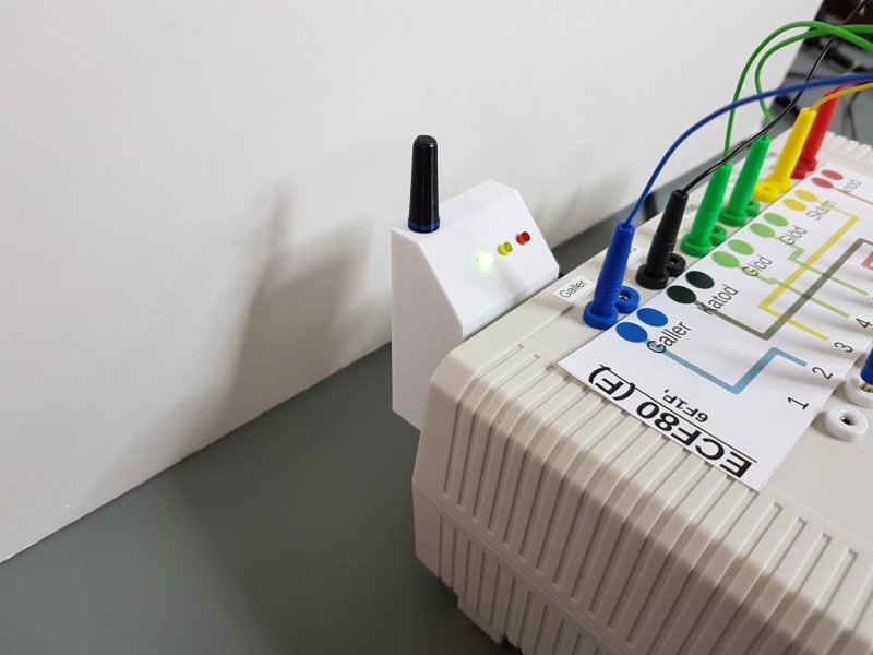
One more thing I wanted to show is how cool that ESP32 module can turn out with the help of 3D printing (courtesy of Tomas, who posts his updates and nice photos in this forum: https://elektronikforumet.com/forum/viewtopic.php?p=1576073#p1576073 )
Helmut Heller
Dec 7, 2020, 11:20:56 AM12/7/20
to utr...@googlegroups.com, Helmut Heller
On 7. Dec 2020, at 17:01, Ihor <iste...@gmail.com> wrote:One more thing I wanted to show is how cool that ESP32 module can turn out with the help of 3D printing (courtesy of Tomas, who posts his updates and nice photos in this forum: https://elektronikforumet.com/forum/viewtopic.php?p=1576073#p1576073 )
Super cool! :-)
But how is the antenna connected? Or is it just a dummy “for the looks of it”?
hh
Ihor
Dec 7, 2020, 12:12:16 PM12/7/20
to uTracer
I believe the antenna is a fake (probably for a moment, or probably he can try to hame that hack, it looks like people solder a wire there). He uses another development board (so the PCB) but the same ESP32-WROOM32 module, the only thing is that module ( https://www.adafruit.com/product/3405 ) is "US-designed" and costs 7 times more :)
At the same time, there are Chinese ESP32 development boards with ending -U that have external antenna. I ordered a few but have not played with them. They will work for sure without any problems, so those who have them can already flash the firmware. The only thing is that pinout for LEDs are slightly different (those ESP32 "U" boards have 38 pins and not 30). I ordered them for a test to see if the wifi reception is way better or the same (for moderate-distance in-house use).
Ihor

Rudie
Dec 7, 2020, 4:04:38 PM12/7/20
to utr...@googlegroups.com
I though that there was a 0 Ohm surface mounted resistor standard on each ESP32 board that you could move to switch between the PCB and the external antenna?
Op ma 7 dec. 2020 17:12 schreef Ihor <iste...@gmail.com>:
--
You received this message because you are subscribed to the Google Groups "uTracer" group.
To unsubscribe from this group and stop receiving emails from it, send an email to utracer+u...@googlegroups.com.
To view this discussion on the web visit https://groups.google.com/d/msgid/utracer/31697b4c-ed46-492f-930d-fbdcd82bb0d7n%40googlegroups.com.
Ihor
Dec 22, 2020, 5:22:51 AM12/22/20
to uTracer
On Monday, 7 December 2020 at 22:04:38 UTC+1 wrote:
I though that there was a 0 Ohm surface mounted resistor standard on each ESP32 board that you could move to switch between the PCB and the external antenna?
As far as I found online, the versions with PCB and IPEX antennas are separate versions and not interchangeable. ESP32 module itself is covered with that metal shield, so it is difficult to get into the "PCB" (even though people do that). There is a hack online where people cut the PCB antenna and solder a wire to make an external one. There is also a version of ESP32-WROOM-32IB or ESP32-S which have both antennas on board. I have not checked those yet, but I ordered a simpler "U" version with IPEX antenna to compare the reception strength. In the future I will post some results.
Meanwhile, I also put on the website the new release (firmware) of the ESP32uTracer interface (ver.0.8). I think this year I will not make more changes but I am looking forward to suggestions and ideas for improvement. Last month, due to user's feedback, lots of things were nicely polished and tested!
Cheers,
Ihor
piamp
Dec 22, 2020, 5:35:31 AM12/22/20
to uTracer
amazing!
i'm now using the esp32 as my main interface. direct TX connection to the IC works great.
i wired a 1.3" screen, it's fun ! but we have to find what usefull things we could print...
maybe the results of the quicktest ?
if you have a paypal account i'll be happy to give a small donation :)
pierre
Ihor
Dec 22, 2020, 6:19:02 AM12/22/20
to uTracer
Thanks Pierre! (I also sent you a private message)
About the screen, indeed, right now it shows some debug information which comes directly from the ESP32 (so if there are some errors are happening, which will not or cannot be sent to the webpage) and it also repeat the information from the LEDs (so one can choose what to use). The only "useful" info that the screen shows now is the IP address and if the password was correct or ESP32 switched to the Access Point mode. During the acquisition, if shows the exchange of measurements, but if ESP32 and uTracer operate without any errors, then all the information is duplicated in the webpage.
I was also thinking to show the quick test values on the screen in the end of the test, and will probably add it soon, but I was a bit slow with that because in practice you are going to see the webpage (on your PC or mobile phone) anyways, with exactly the same results. So, it is a nice feature, but it is a bit of duplication.
I was also thinking of connecting those cool Nextion screens (https://nextion.tech/) which are also not expensive, but those can actually control ESP32 and uTracer (so display the information and get touch-based input).... but then again, you can just open the webinterface on your phone (additionally to the PC) and you do not need that Nextion screen:)
Another idea, it is possible to used ACS712 Current Sensor for example, connected to ESP32, and then that 1.3" OLED can show the current consumption of uTracer, and also the current of the working heater (if one uses external DC heating). In general, any other sensors can be connected to ESP32 and then show the information on the OLED screen, so if someone has a interesting idea, shoot it here!
Cheers,
Ihor
Ihor
Dec 29, 2020, 6:51:27 AM12/29/20
to uTracer
Happy holidays to all!
- the results of the quicktest are now shown on the OLED screen,
- the Quicktest page contains also the Heater menu, so it is now completely self-contained, one can turn the heater on and off and do the quicktests from the same page (which fits nicely mobile phone screens).
- there is a "triode" like icon in the navigation bar of the webpage that will be flashing all the time if the heater is on
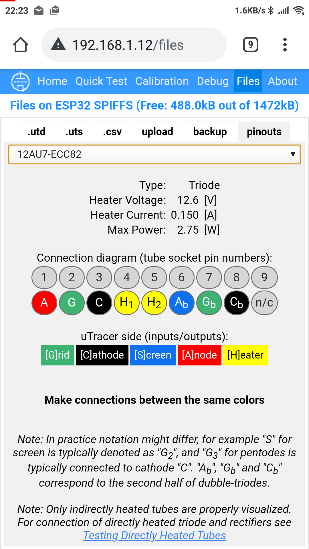
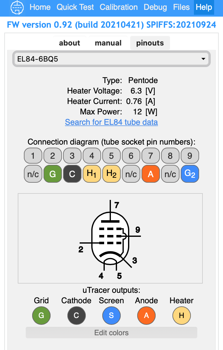
- I hope this last feature will be useful for others as well. Many times I found myself googling how to wire the utracer for a specific tube, even though I used that tube already some time ago. So, in the Files menu I implemented a pinouts tab which contains quick diagrams how to connect utracer to your tube quickly. The pinouts are specified in a very simple text file (see pinouts.csv on ESP32) which you can download, modify and then upload once agin. Probably after some time, via sharing, we can build up nice database (pinouts.csv file) with lots of options.
Cheers,
Ihor


Marc van den Dobbelsteen
Jan 9, 2021, 10:50:31 AM1/9/21
to uTracer
Hi Ihor,
Man, I like your approach here, good job !!
Any thoughts about sharing the application's source code?
I would very like to help extend and/or write some extensions to the app for myself and/or others.
Perhaps sharing on private Github with team-access and using pull-requests from others to extend the codebase?
Cheers,
Marc
Op dinsdag 29 december 2020 om 12:51:27 UTC+1 schreef Ihor:
Ihor
Jan 14, 2021, 8:00:45 AM1/14/21
to uTracer
About the software, I still consider it in a developmental phase, so I will consider the possibilities in the future, depending on in which direction the whole project will go. Right now, the size of the code is also hitting the limit of the standard cheap ESP32 modules with 4Mb of flash, so I have to very carefully implement new features, re-optimizing lots of things in the existing code. Still, ideas about some interesting features are very much welcomed.
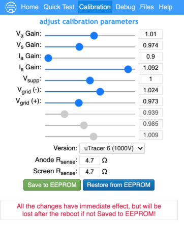
Meanwhile, I released new beta (20210111) which fully supports uTracer6. One has to go to the Calibration menu and select uTracer6 model and put your existing calibration values there (see the screenshot). The extension was done for one the the uTracer6 users who is going to test it with the real hardware. I tested it on my adruino based simulator of the uTracer6 and it communicates exactly in the same way as the windows software for uTracer6 (sending the same commands and values).
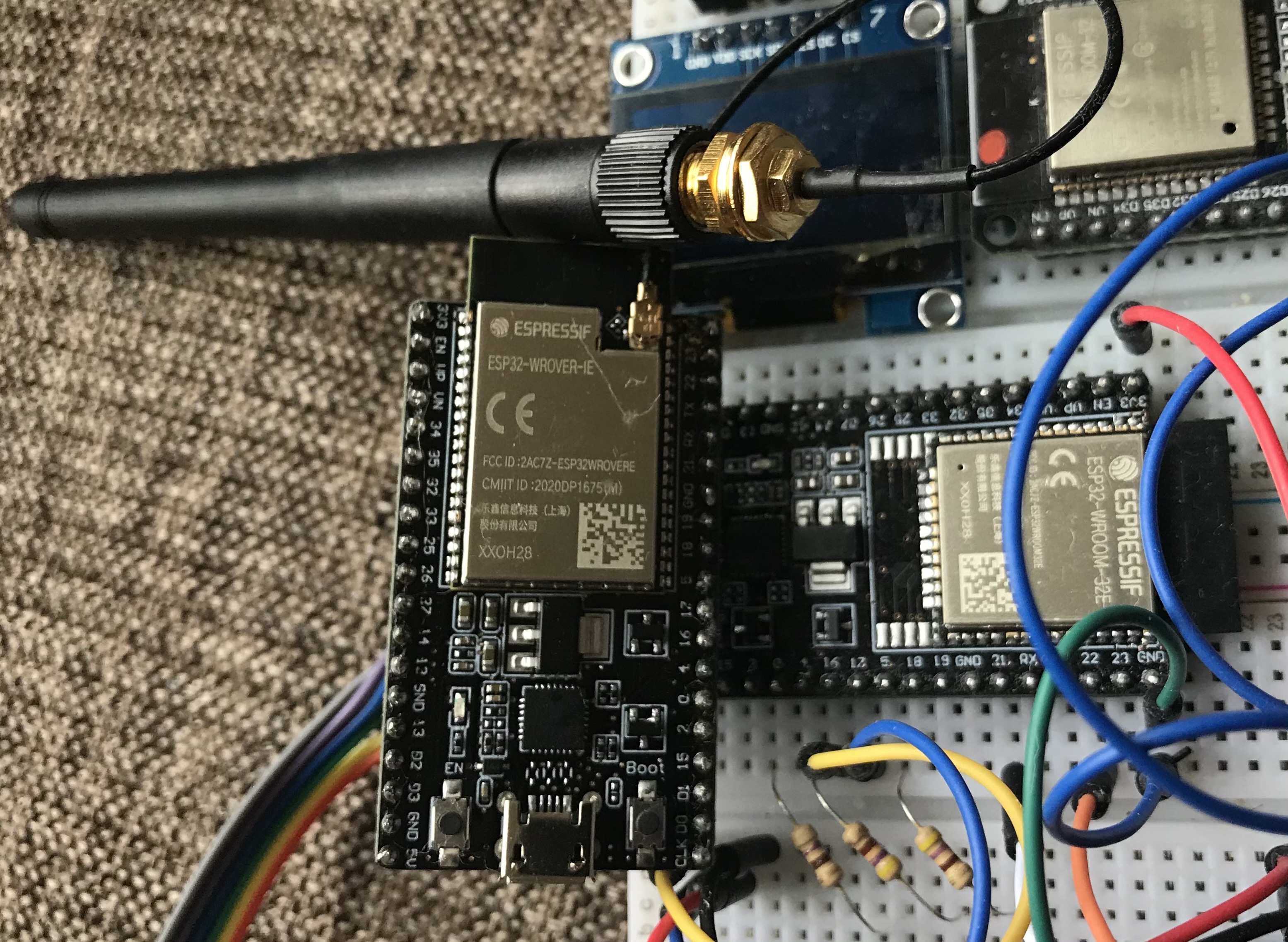
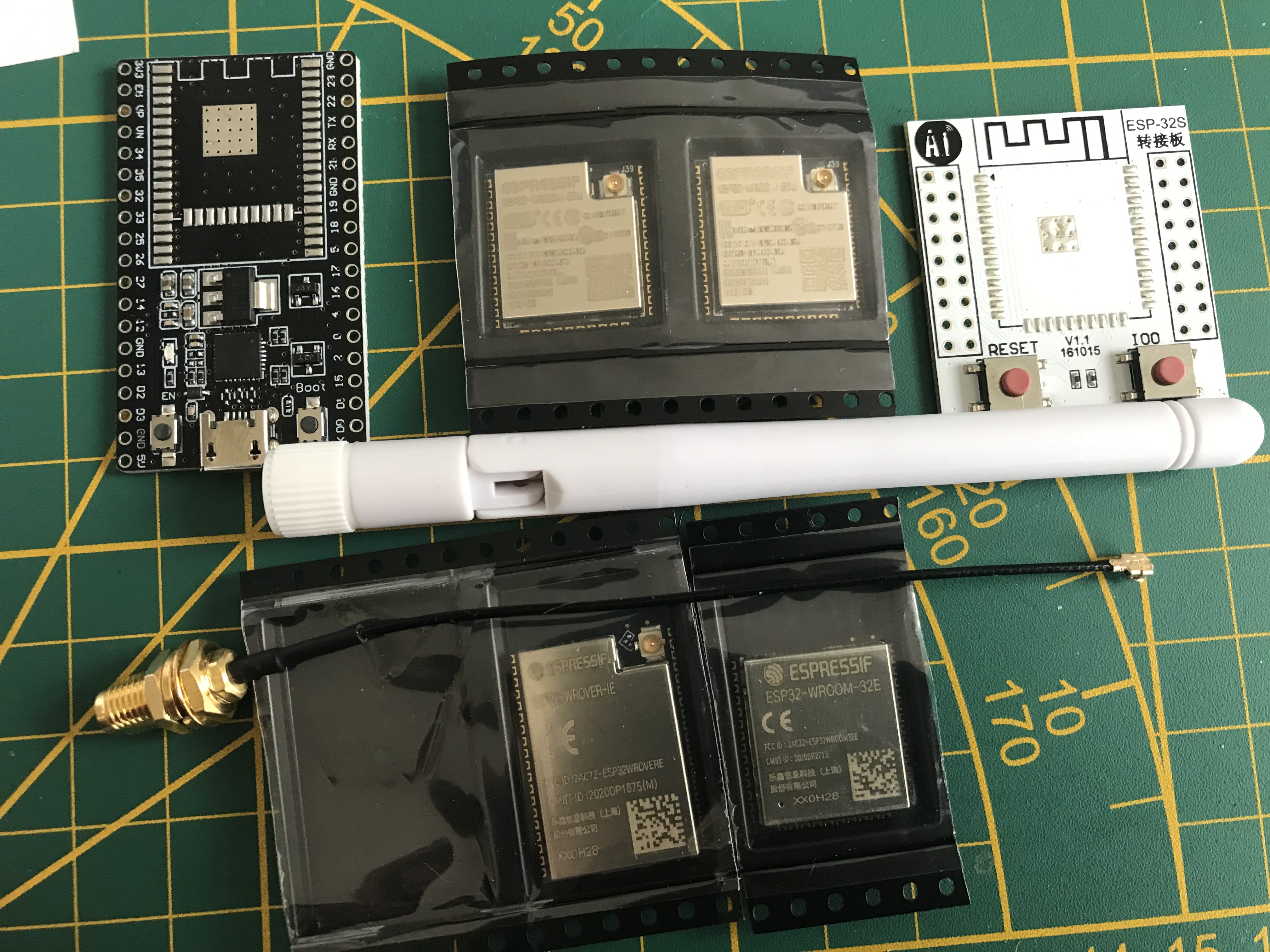
I also got some ESP32 modules with 16Mb flash and external antenna and those are also nice and working great (see some example photos). For the brief comparison, the WiFi reception is better with the modules with external antenna (ESP32-WROVER-IE), but also with the new version of the modules with internal antenna (ESP32-WROOM-32E). Apparently they improved things there as well. The small problem with the 16Mb modules is that you can buy them only as modules, without the PCB/development board, but you can also buy the boards separately and solder everything together. the cost is still ridiculously cheap ($3 (module) + $1.50 (board)).
In terms of the WIFi reception, I still have to do more tests, but so far measurements are like this:
(the borderline reception level is about -70dBm, which is still works when I tried, but lower might be problematic). So in my apartment (7m and 3 walls between the wifi router and the ESP32) the standard ESP32-WROOM-32 shows about -64dBm, ESP32-WROVER-32E is -59dBm and ESP32-WROVER-IE with external antenna is about -49dBm.

Never Mind
Feb 2, 2021, 10:29:59 AM2/2/21
to uTracer
Ihor
Impressive Web demo and project you have created.
I have a uTracer and find it a excellent piece of design. The user interface supplied by Ronald is perfect for the beginner it being simple, clean and easy to use.
I have over time become frustrated by the limits of the
PC
GUI user interface particularity its inability to allow for the creation of
custom
automated measurements.
I find generation and naming of all data files required to create spice pentode model tedious.
A difficulty I have with current uTracer software is that there does not seem to be the ability to set soft current and power limits to bound check current and power
in measuring tubes.
It seems difficult to avoid the over current/power of screens in pentode measurements when attempting to create data sets for spice models.
The user has to set up sweeps carefully to avoid stressing the tube under test or repeatably hitting compliance errors during testing.
So I have started to create my own control software for my uTarcer that will focus less on a GUI and more on simple scripts to allow complex custom measurement sequences to be created where current and power levels can be bound checked and limited automatically.
I started in Python on a PC and have the uTracer command structure defined and working. It is pretty straight forward and
Ronald's web site is excellent.
But much of my time is being wasted dealing with PC based serial port complexities in Python and I have now remembered why I avoid PC based software that needs to deal with a real serial port.
So I decided to move my project to a Arduino based embedded platform as I have some experience in both ESP based WEB
interfaces and control of devices through serial ports with embedded
devices .
Sorry for my long winded preamble. The ESP32 code is going take me some time and I will end up reinventing the wheel as I can see that much of the functionality I will need already exists in your ESP32
Arduino code.
So I wondered if you would consider sharing your ESP32
Arduino code with me as it will save me considerable time and effort.
I understand the calibration code came from
Ronald and this has prevented you from releasing your code in the past.
I wonder if you would consider to releasing your code to me with the calibration code removed (I believe I can recreate what is required) or if this is impossible perhaps you would consider releasing your code to me after I contact
Ronald and receive his agreement.
Let me know what your thinking is and take care.
On Wednesday, June 3, 2020 at 4:25:08 PM UTC-4 Ihor wrote:
Hi Helmut,The initial plan was to put everything to github, and probably in the future I will do so. I might put the javascript quite quickly (even though those who know javascript also know that the code is already in their browsers and can be extracted without any problems). It was also my first experience with javascript in general, so the webpages are far from nice or stylish. I planned to check the CSS and so on in the end of the project :) or probably there will be some designer who would like to make the interface a bit nicer. For now the project is still in the state where things are tested to the very end, to work properly.There is a small thing about sharing the C++ part. It implements the exact calibration procedure and values as used in the Windows software. For example utMax (alternative software for mac and linux) uses its own calibration values and I did not want to have that. It was not possible to get that part working just from the Ronald's logbook, so I contacted him and got some pieces of code in visual basic which I had to reprogram. As I understood, those are not to be shared online, so for now I will avoid that. Still, the C++ portion is also in the testing stage. Also, I am not sure how quickly the project on github will go out of hands.I can easily compile a binary that one can flash in their ESP32 and play a bit. For now I also have not spend much time on making any user interface for the webserver (WiFI login/password part). They should be written in the code and then compiled. I can make a small HotSpot interface that one has to connect to first and put the password to the wifi network or enter the password via serial interface of ESP32, using terminal connected over USB. Those things I have not explored yet.So, for now I just wanted to share more of a progress than the finished product and probably get some extra input to implement some other useful things.One more screencast about more technical details: http://files.smal.ws/3I8cCdCheers,Ihor
On Wednesday, June 3, 2020 at 9:57:49 PM UTC+2, Helmut Heller wrote:Dear Henning,This is so cool! I also own a µtracer and I use the ESP32 a lot (for other things: IoT). Are you willing to share your ESP programs? Maybe on github?Congratulations, this looks awesome!!ByeHelmutOn 3. Jun 2020, at 21:43, Ihor <iste...@gmail.com> wrote:Hi All,Recently I was plying with ESP32 board (a rather cheap (5$) Arduino on 'steroids'), basically learning its possibilities and toying with it and I though that it would be nice to have it connected to uTracer and make it act as a webserver on a local LAN (or even independently as a WiFi Access Point) and do all the measurements (and possible more) via webinterface using a Mac or Linux laptop, ipad or mobile phone. After some attempts I put together such system, which is still highly experimental but it works good for my needs and I was wondering if someone would like to test it in the future or do something similar.I do not have any manuals yet but most of the things are self explanatory. Briefly, I am using ESP32 (a very advanced Arduino like board, for those who are not familiar with it), which runs a webserver, hosts all the webpages, and then uses its GPIOs to connect to uTracer and send AT commands, exactly as the standard Windows software for uTracer does. The software on the ESP32 consists of C++ code and Javascript. The ESP32 can be connected directly to Tx/Rx pins of the PIC controller (of uTracer), or in my case, I use a small adapter (Tx/Rx to RS232), so no changes to uTracer are necessary and the whole system is modular and can be connected via the RS232 interface (just needs 5V power).Right now the system can:- acquire and visualize the measurements in a similar manner as uTracer's windows software- save the measurements on its own flash memory, which can be later on downloaded or uploaded for analysis- multiple curves can be loaded in the plot window (using so-called memory cells, it helped me a lot to match quads of tubes, looking at the curves simultaneously)- plot interactive load lines and output all the parameters for that operation point as well as doing harmonic distortion analysis and so on- model the acquired curves (either acquired by uTracer on the fly, or via uploading the previously collected .utd files) using most of the models that Derk described in his ExtracModel program. I found that program very useful but only windows based. I reimplemented (in javascript) only the models that I was planning to use (only triodes, pentodes and tetrodes, no fancy heptodes and so on).I have some ideas for extra features, but most of them are based on what I typically do with the uTraces. It would be interesting to hear some ideas about possible additions, but it is a really hobby project, which is done over weekends (and not always).I put all the webserver/javascript part of the code online and created a small website so anyone can upload their data and play a bit with the interface. It is located at http://utracer.live There, the 'Acquire' part of course does not work, but all the visualization, modeling and load-line plotting are functional.I made a few screencasts to show how things look in practice.- the data acquisition http://files.smal.ws/RfbGzC- import of the utd files and plotting the load line: http://files.smal.ws/ib0ONu- modeling of triodes and tetrodes: http://files.smal.ws/xnr5WNYou can go to http://utracer.live and try yourself. The photos of the ESP32 and the interface module are also attached.
--
You received this message because you are subscribed to the Google Groups "uTracer" group.
To unsubscribe from this group and stop receiving emails from it, send an email to utr...@googlegroups.com.
To view this discussion on the web visit https://groups.google.com/d/msgid/utracer/ffc7a09a-8d88-4904-b4a9-7eeb51aa110f%40googlegroups.com.
<ESP32uTracer.jpg><RS232uTracer.jpg>
Ihor
Feb 5, 2021, 3:03:13 PM2/5/21
to uTracer
I just posted a new release of the ESP32 firmware (ver 0.9). There were lots of small improvements in several beta versions before, which piled up over quite some time, but recently released update of the HIghcharts library that I have been using messed up a few things in positioning of the titles of the plots, so I had to catch up and decided to put it as a release, because then ESP32's users get a notification to update.
Besides that, the two other major changes is that it now works with uTracer6, and it also has an implementation of internal memory buffer (of 96kB) that allows storing of acquired data points which can be restored on a fly in a browser: now one can jump between the tabs of the webinterface while acquiring the data, or starts the acquisition on the phone and then continue observation on a PC.
Ihor
Ihor
Nov 29, 2021, 3:55:47 AM11/29/21
to uTracer
Hi All,
Now, that I (and some other members) can again post in this groups and see the messages (after some fixes by Gary, thanks!) I just wanted to refresh this thread about the uTracer and ESP32 combination. The project is still alive and all the implemented things are working well, so that's why there are not some many recent updates. The link to the project is here: http://boffin.nl/wp/utracer-and-esp32/ (feel free to check some photos from the used in the bottom of this link).
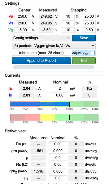
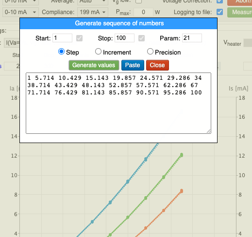
The main updates include the fully functional and tested version for uTracer6. There is also no handy possibility to add and display the pinout of the tubes that you are frequently dealing with (see the screenshot). In the Quick test menu, there is a possibility now to automatically compensate for a small (2-5) anode voltage drops (due to sensing resistors), which is different from the windows software. There, it is also possible to set the desired anode current and uTracer will automatically find the corresponding grid voltage. Such functionality is used by a few users to match the tubes in this peculiar way. The full list of recent updates can be found here: http://boffin.nl/files/firmware_changelog.txt
Feel free to send some photos (build this setup yourself) or suggestions. Even if you do not use that module in combination with the uTracer, you can still flash the firmware and have just ESP32 in your LAM network as a small webserver that hosts the information about the tubes, and let you upload the .utd files from uTracer and play with load lines and SPICE modeling :)
Cheers,
Ihor
Ihor
Nov 29, 2021, 4:12:07 AM11/29/21
to uTracer
...and a few more screenshots, just to give a better overview (those screenshots were also posted in April, but never showed up here because of the issues with the googlegroups).

Daniel J Farrell
Nov 29, 2021, 7:30:58 AM11/29/21
to utr...@googlegroups.com
Hi Ihor,
This is really impressive piece of software.
Can you break down how the web app runs? I have a spare Raspberry Pi, is this something that I could run at home using that, and maybe contribute to the code?
I think we talked a while ago about this, but might be easier now the group is working again. Back then I was interested in writing a Python module which would control the uTracer via serial port. I’m still interested I this, but it has taken a back seat.
Cheers,
Dan
On 29 Nov 2021, at 09:12, Ihor <iste...@gmail.com> wrote:
...and a few more screenshots, just to give a better overview (those screenshots were also posted in April, but never showed up here because of the issues with the googlegroups).
<crosshair.png><newqtest.png><voltagelists.png>
On Monday, 29 November 2021 at 09:55:47 UTC+1 Ihor wrote:Hi All,Now, that I (and some other members) can again post in this groups and see the messages (after some fixes by Gary, thanks!) I just wanted to refresh this thread about the uTracer and ESP32 combination. The project is still alive and all the implemented things are working well, so that's why there are not some many recent updates. The link to the project is here: http://boffin.nl/wp/utracer-and-esp32/ (feel free to check some photos from the used in the bottom of this link).The main updates include the fully functional and tested version for uTracer6. There is also no handy possibility to add and display the pinout of the tubes that you are frequently dealing with (see the screenshot). In the Quick test menu, there is a possibility now to automatically compensate for a small (2-5) anode voltage drops (due to sensing resistors), which is different from the windows software. There, it is also possible to set the desired anode current and uTracer will automatically find the corresponding grid voltage. Such functionality is used by a few users to match the tubes in this peculiar way. The full list of recent updates can be found here: http://boffin.nl/files/firmware_changelog.txtFeel free to send some photos (build this setup yourself) or suggestions. Even if you do not use that module in combination with the uTracer, you can still flash the firmware and have just ESP32 in your LAM network as a small webserver that hosts the information about the tubes, and let you upload the .utd files from uTracer and play with load lines and SPICE modeling :)Cheers,Ihor
--
You received this message because you are subscribed to the Google Groups "uTracer" group.
To unsubscribe from this group and stop receiving emails from it, send an email to utracer+u...@googlegroups.com.
To view this discussion on the web visit https://groups.google.com/d/msgid/utracer/7d6e9d40-91be-400b-a4dd-74739598495cn%40googlegroups.com.
<voltagelists.png><crosshair.png><newqtest.png>
Ihor
Nov 29, 2021, 8:03:21 AM11/29/21
to uTracer
Hi Dan,
Thanks for good words! I did not consider Raspberry pi at that time because it would be jsut an overkill for that application, and way more expensive ($20-30 vs $3) :) Even though of course those prices are ridiculous. Writing for raspberry pi would be also easier to do in pytohn for example. I started with arduino and my first prototype was based on that module and worked quite good, but without all the webinterface and so on. So, ESP32 was a perfect candidate because it has a dual core processor, lots of ram and flash, compared to arduino, and has wifi and bluetooth, it boots in less than a second (compare to RPI), consumes nothing in terms of electricity and SD cards do not get corrupted as with my old RPI :)
The pipeline is rather simple, there is a webserver that runs on ESP32. All the webpages are HTML+javascript that display all the plots and control the parameters, all the SPICE modeling (curve fit, THD analysis, etc. are written in javascrip and run in a browser). All the files are stored in ESP32 flash, which is accessible in a browser. The main "engine" is written in C and runs on ESP32, it just listens to the request from the webserver and executes basic uTracer commands by communicating with uTracer via the serial interface. That part is quite straightforward and there is nothing much to add there. All the "commands" or requests for any type of measurement are formed within the webpage and there is a simple API that one can use to ask ESP32 to execute that command with uTracer. The "translation" between the commands and received values are nicely described on Ronald's website. So, one can even write a python, javascript or any other possible HTML GET/POST request (even from the linux terminal) and get the measurements back, creating all possible acquisition loops. Over the time I only got a few requests to improve some user experience, but I have not got any serious suggestions which would need a lot of time.
It is a hobby project, so I would not have time anymore to spend on it, as much as I want. Meanwhile I moved to other things as well :) I recently build a nice 4-channel spectrum analyzer based on ESP32 and a simple cheap FPGA board (see here http://boffin.nl/wp/fpga-thd-analyzer/ but it is still under development) with a build in generator for my THD and intermodulation measurements. It measures really nicely (up to 0.001%THD which is an overkill for tube-audio) :) I had experience with ESP32 but FPGA was completely new to me. Now everything works great, also with the live preview and update in webbrowser, with max sampling of 200kSamples/sec and possibility to collect up to 128k samples per channel. The price here was also ridiculous ESP32+FPGA+ADC board+SRAM chips is about $50 (compared to the commercial solutions that I saw). This project is more difficult to repeat but if someone is interested, feel free to ask. It is possible to make a printboard for the future and have it as a DIY set, but again, unfortunately no time.
Cheers,
Ihor

Davo
Nov 29, 2021, 3:50:57 PM11/29/21
to utr...@googlegroups.com
I was busy many weeks trying to get uTmax running on a raspberry.
But i gave up haha the software was writen in x64 & to convert all the files arm64 was a nightmare for me.
I gave it up haha
But uTmax has nowadays have some cool functions which the uTracer soft dusn’t have.
Grtz,
--
You received this message because you are subscribed to the Google Groups "uTracer" group.
To unsubscribe from this group and stop receiving emails from it, send an email to utracer+u...@googlegroups.com.
To view this discussion on the web visit https://groups.google.com/d/msgid/utracer/5ee2198c-8157-4bf9-bbc8-160e6dbeaf1bn%40googlegroups.com.
Ihor
Nov 29, 2021, 5:30:56 PM11/29/21
to uTracer
Hi Dave,
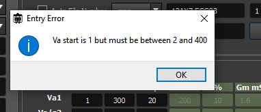
I am curious what kind of features are those? I remember I tried uTmax a few years ago and it was working also fine but I do not remember any features that I missed at that point. The calibration values of uTmax are different from the uTracer calibration values and that I found annoying (that’s why calibration for the ESP32 is exactly the same as in uTracer software). uTmax might also not work with uTracer6 because the calibration algorithm is different and not fully disclosed so I had to reverse-engineer it. uTmax can also easily hang uTracer just by setting the Va to less than 2V :) there was no check for that and the protocol and windows software for uTracer explicitly forbid that… but probably things have changed since I tried it.
Ihor
Davo
Nov 29, 2021, 6:32:36 PM11/29/21
to utr...@googlegroups.com
Hi Ihor,
I didn’t tried it that much since the last update v1.58, but when i tested it was was quite easy to setup. And calibrate..
I have the uTracer 3+ 400v
I honestly don’t know it it supports version 6.
The download specs etc are on https://bmamps.com/v01/home/techie-corner/utracer/
I run it on a mini pc 12x12 cm with win10.
At the moment i’m still busy building and modifying the rat tube which in want to integrate with my utracer…
Mainly for weeding out the bad tubes etc.
And use the utracer for matching tubes and transistors.
The goal is all in 1 case.
That’s why i went for the raspberry.
I have a 19inch screen build in top of the case. A mini pc for the utracer and a usb scope. To test tubes, a switch matrix because i don’t like those patch cables.
Still loads of work to do lol
It became quite a huge project.
Which gonna take a few months i guess…
Ah well at the end i will get there.
Just a matter of time, dedication & trial and error…
Grtz
Dave,
Verstuurd vanaf mijn iPhone
Op 29 nov. 2021 om 23:30 heeft Ihor <iste...@gmail.com> het volgende geschreven:
Hi Dave,
--
You received this message because you are subscribed to the Google Groups "uTracer" group.
To unsubscribe from this group and stop receiving emails from it, send an email to utracer+u...@googlegroups.com.
To view this discussion on the web visit https://groups.google.com/d/msgid/utracer/145368b3-8982-4e07-8b24-61587b29f74dn%40googlegroups.com.
Ihor
Nov 30, 2021, 4:41:52 AM11/30/21
to uTracer
Nice setup! Adding automated relay-based pin configuration controlled from the EPS32 is actually very easy, and I previously saw on Ronald's website that one of the users already designed a PCB for that. For my infrequent experiments/measurements with uTracer I am fine with switching the cables:)
My initial goal with ESP32 controlled uTracer was to have something that works with Mac's, ipads (tablets) and phones (as well as linux machines) :) Now it works nicely, and one does not need any small desktops and monitors on the table. With that module it is actually possible to take your uTracer to do "field" tests, for example by going somewhere to buy tubes from someone, not expecting to have an internet connection or windows machine there. one can actually buy a super cheap 7" android tablet and build it in the case with utracer.
Nowadays, there is a serial library for Chrome, so one can communicate with uTracer directly via chrome, using javascript for example, so it again makes the whole system independent of your operating system, but you have to like Chrome then.
Ihor
Ihor
Nov 30, 2021, 4:49:44 AM11/30/21
to uTracer
By the way, for those who want to see the debug information from ESP32 or something else via serial and do not want to use Arduino's IDE terminal or any other external tools, here is the Chrome terminal which is always accessible and easy to use:
Ihor
Jan 30, 2022, 3:35:20 AM1/30/22
to uTracer
In order not to pollute the other thread, for those who want to try esp32 webinterface, you can use one of the following links (the old one http://utracer.live does not work anymore):
This is the webinterface with the most recent version which also can acquire traces (in this case Arduino is faking utracer measurements). It runs on real ESP32 at my home but might be switched off from time to time. Also I am not sure how it will behave if multiple people start using it at the same time :)
This is the older version of the interface which is hosted outside and is always available and multiple users can used it at the same time
If you want to get one of those modules, just let me know!
Cheers,
Ihor

nickb
Apr 24, 2022, 8:45:11 AM4/24/22
to uTracer
Just for the record, uTmax has always disallowed voltages less that 2. It gives you an error message if you try it.
Ihor
Apr 24, 2022, 12:14:47 PM4/24/22
to uTracer
It was a long time ago, but I think the problem there (and in my case) was that because the calibration values differ from the original software, I tried some values, without proper calibration most likely, and then even for 2V the uTracer was hanging. This is basically happens because uTracer has a lower "threshold" for those "2V" at the level of PIC controller, which accepts not actual voltages but some HEX values. So with incorrect calibration, those 2V or even 3V can be converted to the HEX command which uTracer does not want to execute. Somewhere on the forum I was posting that string, which you can sent from the terminal window and hang uTracer.
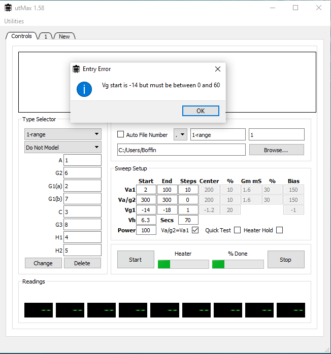
I think I am just not handy with uTmax. I just opened it (after long time), everything is by default, so I did not even change any parameters, which look quite reasonable, and after pressing Start I get very weird error that my grid voltage should be positive, and no indication why it is wrong.
Ihor
Apr 24, 2022, 12:23:27 PM4/24/22
to uTracer
So, for example, this command will still work
10002F002F0002006E
but
10002800280000006E or
10002A002A0000006E
will already hang utracer, so that 002A is more or less the critical value below which utracer will not run. With incorrect calibrations, 2V can be easily converted to 002A (and would not work) or into 002F and it would work. This info might be interesting for some who is going to play around with the communication protocol. Those commands can be sent from any serial terminal connected to uTracer, for example using Arduino IDE.
Davo
Apr 24, 2022, 4:19:46 PM4/24/22
to utr...@googlegroups.com
Ronald should implement that also,
Better a failure message then a hang
Verstuurd vanaf mijn iPhone
Op 24 apr. 2022 om 18:23 heeft Ihor <iste...@gmail.com> het volgende geschreven:
So, for example, this command will still work
--
You received this message because you are subscribed to the Google Groups "uTracer" group.
To unsubscribe from this group and stop receiving emails from it, send an email to utracer+u...@googlegroups.com.
To view this discussion on the web visit https://groups.google.com/d/msgid/utracer/0f345080-986c-4d34-83b8-9c8d8f03b75cn%40googlegroups.com.
nickb
Apr 29, 2022, 5:45:47 PM4/29/22
to uTracer
This will happen if you didn't put the utmax_files folder in your home directory per the instructions. There's an installer nowadays to make it easier.
Ihor
Jul 17, 2022, 3:14:54 PM7/17/22
to uTracer
Yet another small update about the ESP32 combination with uTracer. Recently I got a M5Stick-C as a donation (thanks Paul!) which is a nice alternative to what I have been using before. It is a ESP32 module in a nice plastic case, which has lots of features and sensors, including a small screen, batteries, case, buttons, builtin red LED, accelerometers and so on. A huge overkill in terms what is inside but very nice fit for webinterface because everything is there (ESP32, case and screen). It is more expensive that a standard ESP32 from China, but it is sill OK.
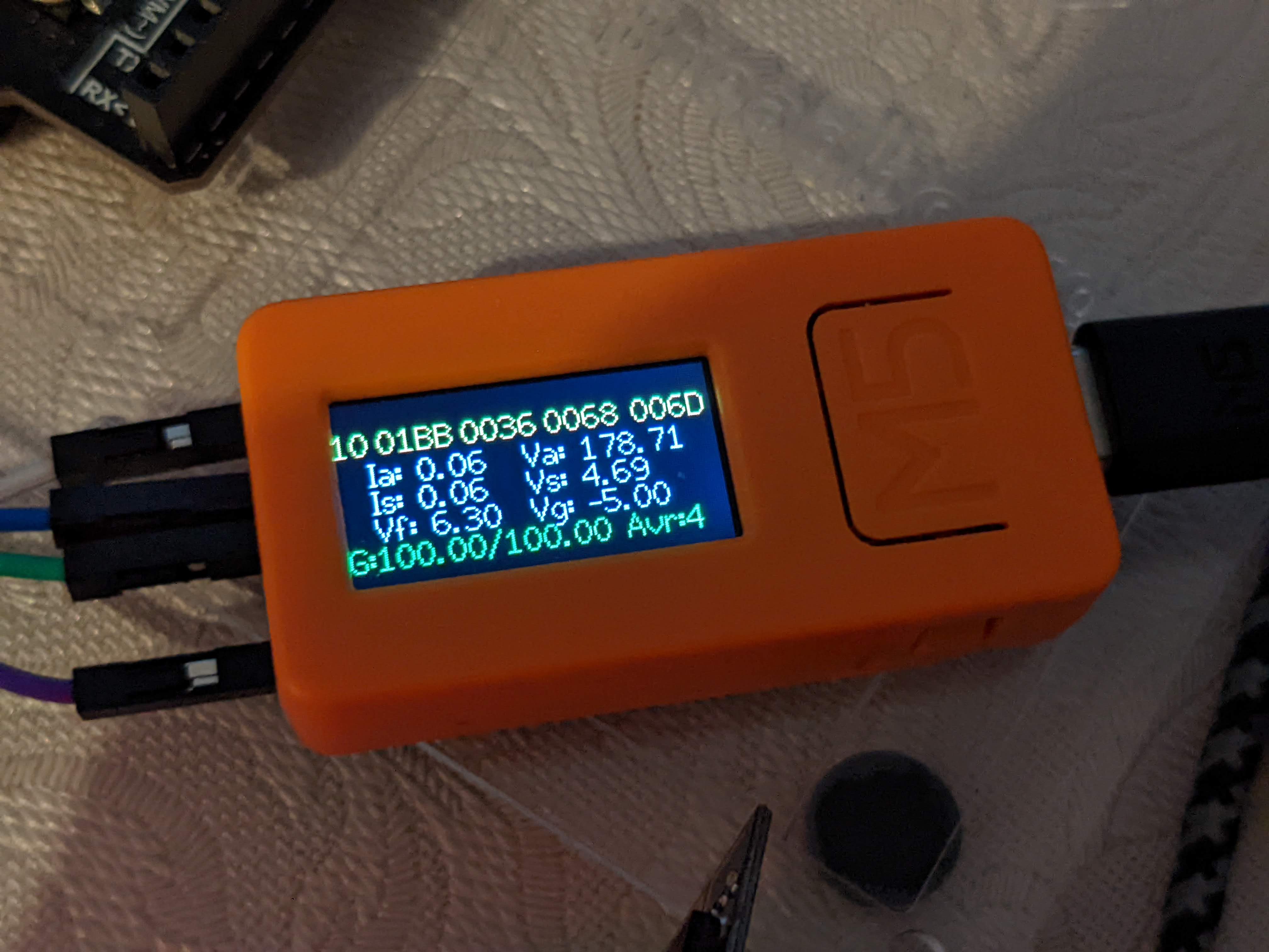
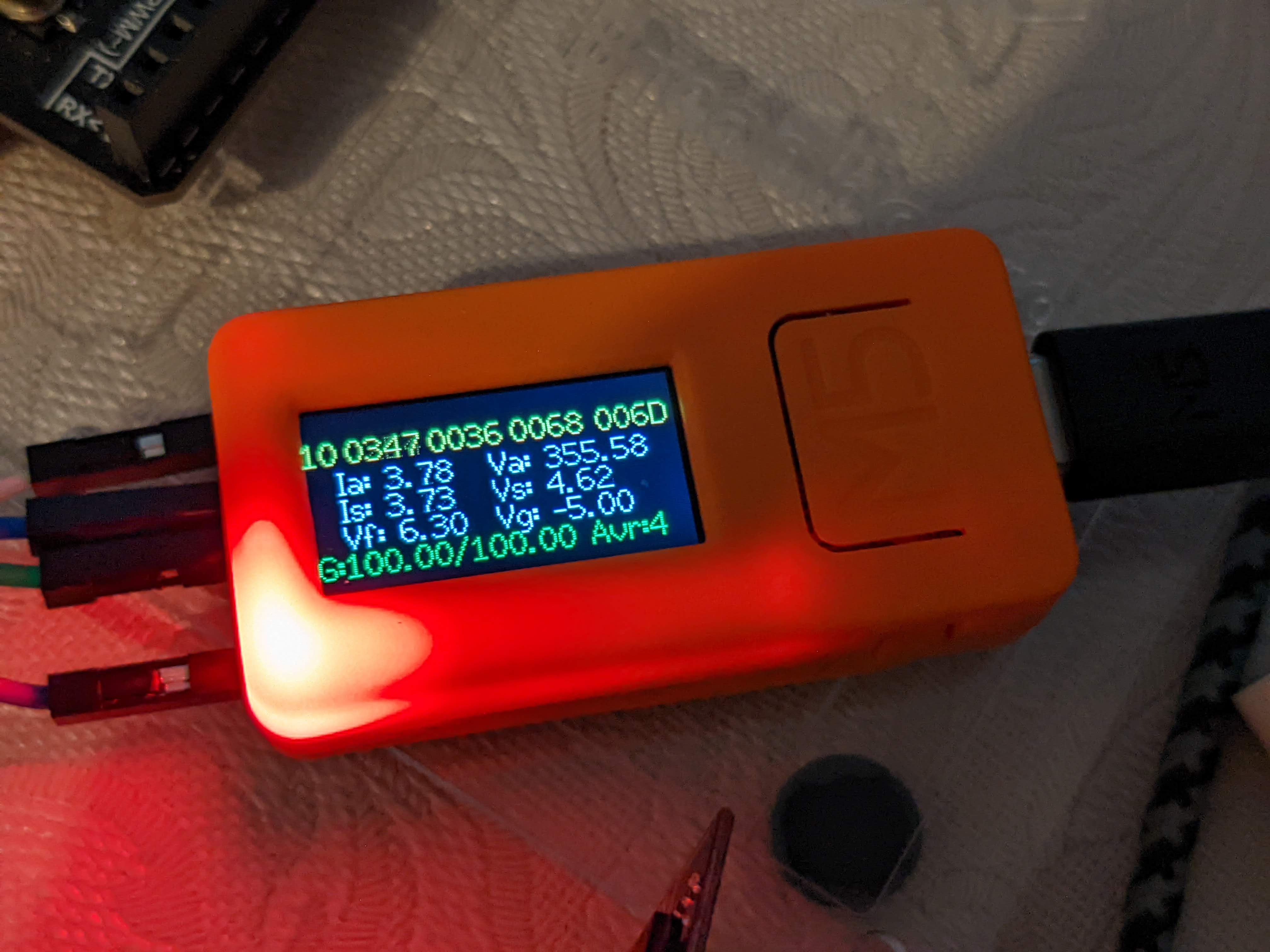
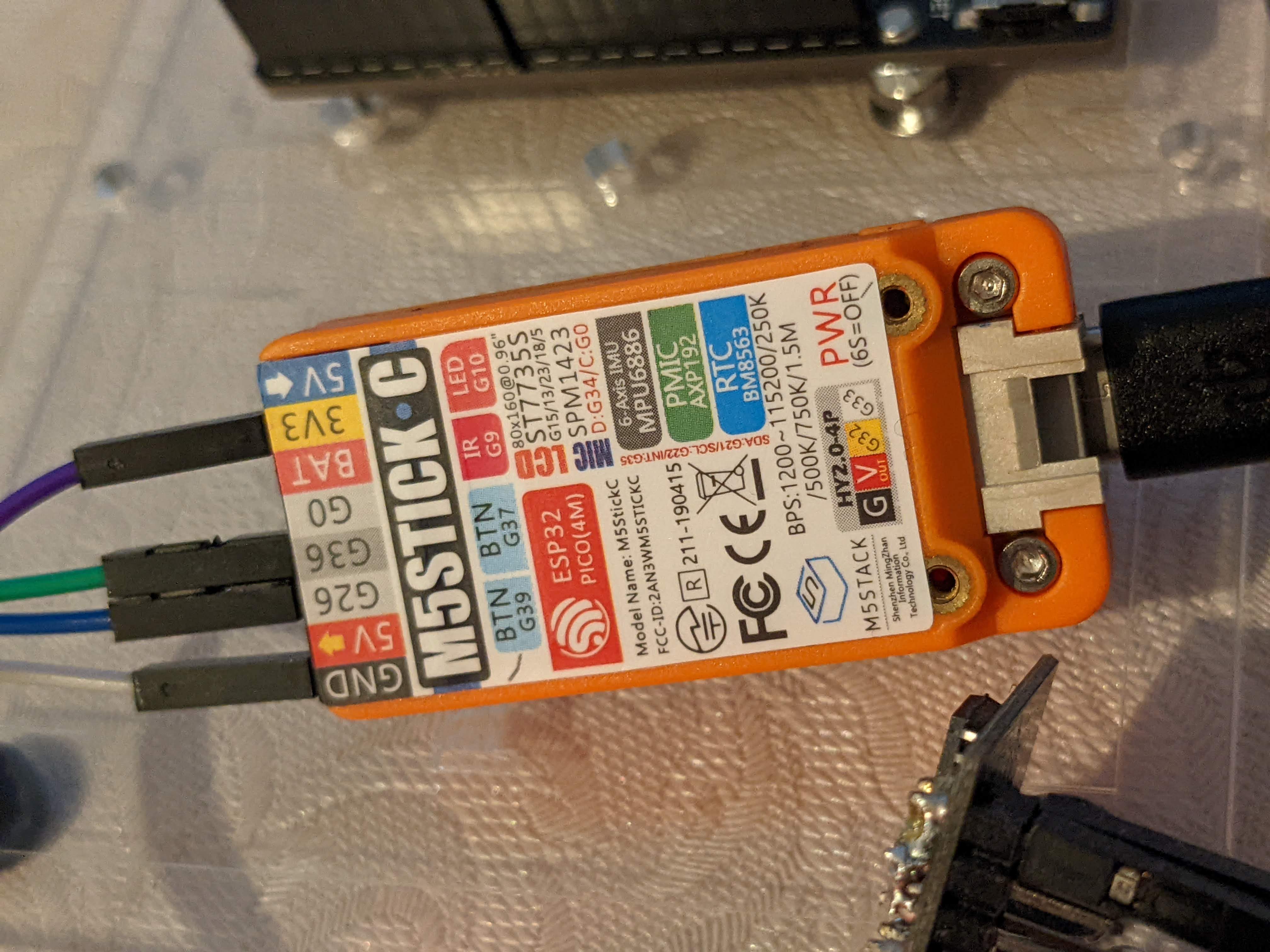
Even more, it can be nicely connected directly to the TX/RX of PIC controller in uTracer, so no extra devices are required. I recently also read that even though ESP32 modules are "3.3V devices", apparently their input pins are 5V tolerable. The official datasheets do not show that anymore because people start powering them from 5V which is not the idea. With that M5Stick-C I did experiments with 5V Arduino uTracer simulator and everything works. Probably still one has to be careful and use a small voltage divider for RX pin on ESP32 (or a standard level-shifter).
The webpage how to install it is updated: http://boffin.nl/wp/utracer-and-esp32/
Here are some photos and a small video: https://youtu.be/r5wnCNdgGNQReply all
Reply to author
Forward
0 new messages