Broke my nanoKENBAK-1?
149 views
Skip to first unread message

Rolf Strand
May 23, 2021, 7:49:29 PM5/23/21
to uKenbak-1
When I turn on the power no animation.
Amber LEDs stays off.
Reset pin is high.
Scope shows oscillator running at 16MHz
1V peak, 0.25v min on pin6, smaller signal on pin 7
VCC 4.17 with usb charging. 4.04 not charging.
Any ideas?
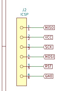
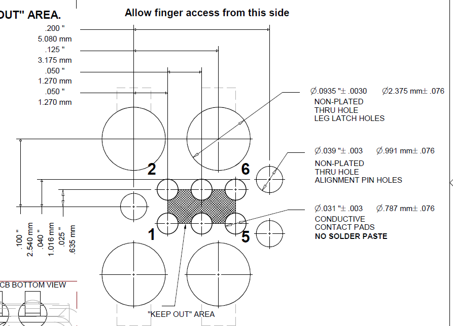
What is the pinout of the 6 little dots?
I assume this is the ISP port.
Maybe I can try to debug/reprogram
Would need to make tiny pogo pin adapter or microscope and tiny wire and solder.
If no fix. I will remove shift registers and micro, and convert to the min hardware proto schematic with wires to a UNO proto shield.

famousd...@gmail.com
May 23, 2021, 8:25:12 PM5/23/21
to uKenbak-1
Don't be so quick to tear it apart. Make sure the LIR2032 battery is charged. It will not operate with a dead battery, or with the battery removed. Check the continuity on the atmega328 pins.
Rolf Strand
May 23, 2021, 10:47:19 PM5/23/21
to uKenbak-1
I have and UNO and I programmed it with the KENBAK-1 code to see what active signals look like.
Pin 17 is the clock for the button scan. Fast 16 clocks ever 20ms.
Not so on the nano board.
I wondered if maybe the Arduino bootloader was still intact, but the application was corrupt somehow.
I had previously added a header to use the uart for download and upload, and that had been working.
Since I did not have DTR to reset the AVR, I kept trying the manual reset when the sketch was trying to upload.
Eventually I got it to catch and successfully re-flashed the nanoKENBAK-1.
Do not know how it got corrupted.
Guess it is now back to scratch building the min part KENBAK-1 setup.
I have added integral control to the proportional control algorithm
Also I have ordered some SPI temperature sensors: ADT7301
These are simple to interface and have good resolution: 1/32 degree C
Below is a proto of the Temperature sensor SPI read code.
With the addition of the Integral control and the SPI temperate read,
the old axiom of "Software is like a gas, it expands to fill the volume" is holding true.
Only a few bytes left.
; ADT7301 read routine
; OUTPUT.0 SPI Chip select (inverted externally so can leave low for antHeat)
; OUTPUT.1 SPI Clock
; INPUT.0 SPI MISO
;
; This is not totally accurate for values outside of normal
; Room temperatures (extra bits in least significant 3 bits)
load X,20 ; get 20 bits to scale to 1/2 C resolution at the decimal point
jmk spiread ; read spi sensor
store A,sense
store B,senseh
...
shl16b db
sft B,L,1 ; shift left B
skp 7,0,A ; check b7 A
set 0,1,B ; b7 A was high set b0 B
sft A,L,1 ; shift left A
jmp (shl16b)
; OUTPUT b0 = CS, b1 = CLK, INPUT b0 = MISO
spiread db
spibit set 1,1,OUTPUT ; clock hi
set 0,1,OUTPUT ; select chip (inverted ext)
set 1,0,OUTPUT ; clock low
jmk shl16b
skp 0,0,INPUT ; check input bit
set 0,1,A ; bit high, save it
sub X,1
jmp X,NE,spibit
set 0,0,OUTPUT ; deselect chip
jmp (spiread)

fcpr...@gmail.com
May 24, 2021, 6:47:49 AM5/24/21
to uKenbak-1
This would imply that the ATmega328p on the nanoKenbak-1 has the serial uart bootloader installed. I had asked Chris about that and he said it wasn't installed, so it is curious indeed that you were able to do this.
fcpr...@gmail.com
May 24, 2021, 7:16:37 AM5/24/21
to uKenbak-1
Wow, I just hit the reset line on one of my nanoKenbak-1s, and sure enough there was a 1-second delay before re-starting the sketch, so the bootloader must be installed!
famousd...@gmail.com
May 24, 2021, 10:00:45 AM5/24/21
to uKenbak-1
Yeah, I started adding the bootloader after your post a while ago. I didn't realize the Arduino IDE automatically compiled a "with_bootloader" version when you export the compiled binary.
fcpr...@gmail.com
May 24, 2021, 10:03:51 AM5/24/21
to uKenbak-1
Whoopie, it worked! I made a batch file that said:
avrdude -Cavrdude.conf -v -patmega328p -carduino -PCOM12 -b115200 -D -Uflash:w:Kenbakuino.ino.standard.hex:i
Then put avrdude, avrdude.conf, and the hex file in the same directory and prepared to run the batch file (but didn't hit enter yet).
Then hooked up COM12 (an FTDI232 breakout board) to my serial-ported nanoKenbak-1, switched it on, tapped reset pad with a ground (through a 1K resistor in case my probe went astray) , and quickly hit enter. Bingo, batch file ran and my nanoKenbak-1 is now flashed with the latest firmware!
Thanks Rolf for reviving your nanoKenbak-1 and letting us know the bootloader works.
fcpr...@gmail.com
May 24, 2021, 10:08:08 AM5/24/21
to uKenbak-1
Yeah, I just saw that myself only about a half hour ago.
On Monday, May 24, 2021 at 10:00:45 AM UTC-4 famousd...@gmail.com wrote:
... I didn't realize the Arduino IDE automatically compiled a "with_bootloader" version when you export the compiled binary.
Rolf Strand
May 26, 2021, 4:51:56 AM5/26/21
to uKenbak-1
I found that the manual reset method is risky. I got it started and then I tapped reset again.
Bricked it, no bootloader now?
Got pogos on order to make ISP adapter.
fcpr...@gmail.com
May 26, 2021, 7:20:35 AM5/26/21
to uKenbak-1
I'll burn that into my memory banks: Don't tap reset while upload is in progress! Thanks for the warning.
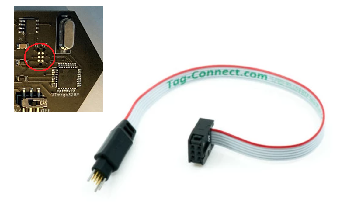
You're literally going to make a Tag-Connect connector? Those pins aren't on 0.1 inch centers.
Rolf Strand
May 26, 2021, 10:01:17 AM5/26/21
to uKenbak-1
I will drill a block of Delrin for the holder on my mill. Epoxy in place after soldering on the cable.

Scott Lawrence
May 26, 2021, 2:00:08 PM5/26/21
to Rolf Strand, uKenbak-1
I can't find these answers in this thread;
1. What is the pinout of the 6 pins on the nanoKENBACK-1 ? (I assume it contains the
standard ATmega/Arduino ICSP pins (MOSI, MISO, SCK, VCC, GND, RST)... and I would
guess they're in the same orientation as Arduinos, but i have not buzzed them out yet...
2. Is there a full schematic of it available?
The only schematic I can find is this one here: https://github.com/funnypolynomial/Kenbakuino
however, it does not include the 6 pin header, and it also shows the TX and RX of the
ATmega connected to TX and RX of the USB port, but i don't see those connected on mine.
... which would be neat if they were, since it would have been nice to make an adapter to bring
it out to be FTDI TTL Serial ... ;)
I at least would like to tag the reset line to see if i see that 1 second delay mentioned above... altbhough
I don't feel like mine has the bootloader.
-s
--
You received this message because you are subscribed to the Google Groups "uKenbak-1" group.
To unsubscribe from this group and stop receiving emails from it, send an email to ukenbak-1+...@googlegroups.com.
To view this discussion on the web visit https://groups.google.com/d/msgid/ukenbak-1/07da03ed-3681-4d3b-9f25-3ae0b2123ad9n%40googlegroups.com.
Scott Lawrence
yor...@gmail.com
yor...@gmail.com
fcpr...@gmail.com
May 26, 2021, 3:59:48 PM5/26/21
to uKenbak-1
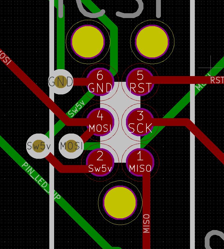
I don't know which pad position is which on the board except that the upper right (right one near the two holes) pin is RST.
The ATmega RX and TX lines are not connected. I hacked in a serial port by soldering wires to RX and TX and connecting to a pin header.

Vicente González
May 26, 2021, 5:33:48 PM5/26/21
to fcpr...@gmail.com, uKenbak-1
To view this discussion on the web visit https://groups.google.com/d/msgid/ukenbak-1/b384c052-d8c6-4810-82c9-d1d38c79f387n%40googlegroups.com.
Vicente González
May 26, 2021, 5:50:38 PM5/26/21
to fcpr...@gmail.com, uKenbak-1
Rolf Strand
Jun 10, 2021, 12:00:50 PM6/10/21
to uKenbak-1
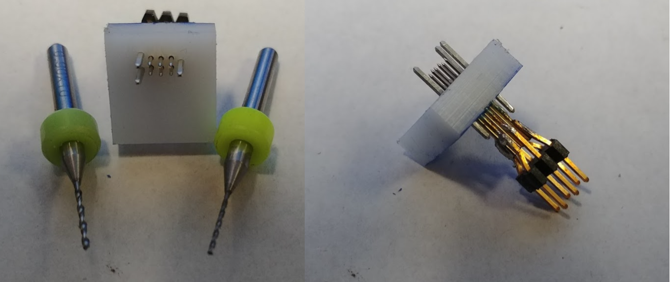
Built pogo programming adapter. Guide pins from 0.1 header strip. Milled block from scrap of Delrin, drilled with 0.7mm and 0.9mm carbides. My milling machine is a large table Bridgeport clone from Spain. Was not sure the 3000 RPM spindle would be fast enough to not break the 0.7mm and 0.9mm carbide PCB drills. But careful pecking worked. Salvaged guide pins from 0.1 inch header nice press fit into the 0.9mm holes. Superglued the pogo pins from the top. Bent legs on 2x3 0.100 header and soldered to pogo pins. May strengthen connector with JB Weld putty. Pogo pins are 0.68mm from Amazon $8.89 for 100. I have 94 pogo pins left for other projects.
Frank P.
Jun 10, 2021, 12:55:45 PM6/10/21
to uKenbak-1
Nice DIY, certainly something I wouldn't have been able to do.
Did you flash the nanoKenbak-1 from the "with_bootloader" version of the firmware hex file so you won't always need to use this?
On Thursday, June 10, 2021 at 12:00:50 PM UTC-4 rolf.l...@gmail.com wrote:
Built pogo programming adapter...
Rolf Strand
Jun 10, 2021, 9:08:46 PM6/10/21
to uKenbak-1
Until I get the reset pin tied to a capacitor and the correct pin on the FTDI converter I am using the ISP adapter. I have a old JTAGICE3 so I use Sketch->Upload Using Programmer.
So the bootloader is there if I need it.
Frank P.
Jun 10, 2021, 9:59:22 PM6/10/21
to uKenbak-1
0.1μF
capacitor from the FTDI adapter's DTR line to the reset pin, plus a 10K pullup resistor on the reset pin. The DTR goes from 3.3V to 0V when the COM port connects, starting the bootloader.
Since the timing is then synchronized automatically, you can let the IDE run avrdude instead of running it manually. Since I expect to do this very infrequently on the nanoKenbak-1, I just used the manual method (very carefully). I did put the RC circuit in my
µKenbak-1 because it's inside a case.
Reply all
Reply to author
Forward
0 new messages