Fried Mosfet, Bed too hot, want to use 400W heater with a smoothie ? ->Heater Buffer
317 views
Skip to first unread message

ChrisHS
Dec 2, 2013, 3:48:20 PM12/2/13
to trinityl...@googlegroups.com
Heater bed mosfet setup has problems
Latchup, ground loop, gate pickup, linear region overheat, unprotected gate, poor heatsink attachment, usb spikes ...
When the fet latches or dies it does so continuously ON.
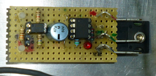

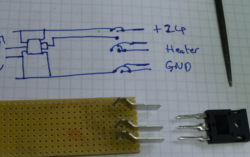
Arduino needed a ground reference for the opto so I added a pair of pins for easy plugging into & then joined to a nearby ground.
Hot melt glue toughens up the area from being pulled around.

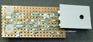
Second (repeated) pic shows the spacers.
I used 6mm, they were a bit short so use 8mm.
This depends where you solder the mosfet & bend it.
Any questions/mistakes that need fixing just ask.
Enjoy,
Chris
Latchup, ground loop, gate pickup, linear region overheat, unprotected gate, poor heatsink attachment, usb spikes ...
When the fet latches or dies it does so continuously ON.
I wanted a cheap circuit to make it work reliably & more safely.
This also allows a smoothie to control the 400W heater.
First go works after moving a few connections around.

I started with a fet driver IC from microchip
(TC4432)
that is latchup protected.
Unfortunately the Arduino isn't & so an opto-isolator is needed to prevent this.
I've added jumper connections for thermostatic switches to be added to the bed.
If the bed overheats the gate drive is switched off.
This is much easier than running 17 amp bed power through the thermoswitches.
So small low current thermoswitches are used with thin flexible wiring.
If the sensor wires break then the heating turns off.
As there is a lot of noisy unshelided currents nearby so I've used 10mA for the opto drive & control circuit switching to make it less likely to respond to pickup.
A twisted pair gate drive with return earth is also used for the same reason.
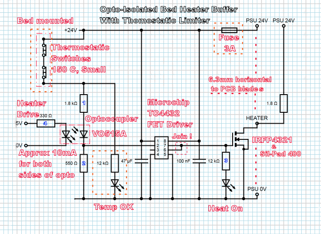
There are optional bits of the circuit depending on how worried you are about your wiring.
Fuse for the gate drive if you think the bed wires might short out from wear & tare.
eg The bed temp OK led.
Fuse for the gate drive if you think the bed wires might short out from wear & tare.
eg The bed temp OK led.
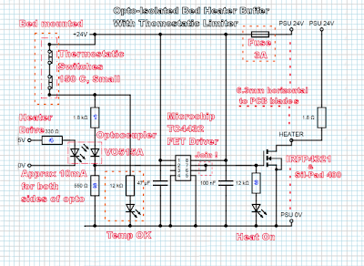
Redid the board layout & came up with this from the circuit above.
Fuse not added as mine is inline from the psu 24V


Approximate Component list
URLs more for reference than being the cheapest supplier
Arduino
2 - Pin strip
1 - Twisted pair jumper cable (2 pin socket to socket)
Heater Buffer
1 0.1uF ceramic 2,5mm, 0.1uF http://uk.rs-online.com/web/p/ceramic-multilayer-capacitors/5381310/
1 47u Electrolytic capacitor 5,5mm, 47 uF 50 V. http://uk.rs-online.com/web/p/aluminium-capacitors/0378592/
2 - Stand-offs http://uk.farnell.com/duratool/d01495/hex-threaded-spacer-nylon66-natural/dp/1733427/
4 - Pin strip http://uk.rs-online.com/web/p/pcb-headers/3606257/
12 - Socket strip http://uk.rs-online.com/web/p/pcb-pin-socket-strips/2677400/
1 - LED 3mm, grn http://uk.rs-online.com/web/p/visible-leds/0826638/
1 - LED 3mm, red http://uk.rs-online.com/web/p/visible-leds/0826622/
3 - 6.3mm horizontal to PCB blade Page doesn't show bend http://uk.rs-online.com/web/p/solder-tab-terminals/0534840/
1 IRFP 4321 Mosfet MOSFET N-Channel 150V 78A HEXFET TO247AC http://uk.rs-online.com/web/p/mosfet-transistors/6887005/
1 TC4432 Gate driver MOSFET Driver 1.5A High-Speed 30V PDIP8 http://uk.rs-online.com/web/p/mosfet-power-drivers/6684395/
1 V0615A Opto-isolator Optocoupler Trans 50-600% 5mA 110C DIP4 http://uk.rs-online.com/web/p/optocouplers/7733684/
1 Thermal pad Sil-Pad 400 0.9W/mK 25.4x19.05x0.178mm http://uk.rs-online.com/web/p/thermal-gap-pads/7073367/
4 - Jumper wires
1 - Crimp blade socket for 24V from PSU to board
1 - Bolt for securing mosfet to bed plate
1 - Fuse & holder for 24V to circuit http://uk.farnell.com/cooper-bussmann/bk-gmd-2-r/fuse-cartridge-2a-5x20mm-time-delay/dp/1150661/
Thermoswitch
1 - Twisted pair thermoswitch cable (2 pin socket to solder wired ends)
2 - Thermoswitches MICROTHERM T11A15005U112L310100 THERMAL SWITCH, NC, 150°C, 2 at least
Hysteresis 30+-15 K so 105C to 120C switch back on
Mount thermoswitches in series away from fan airflow.
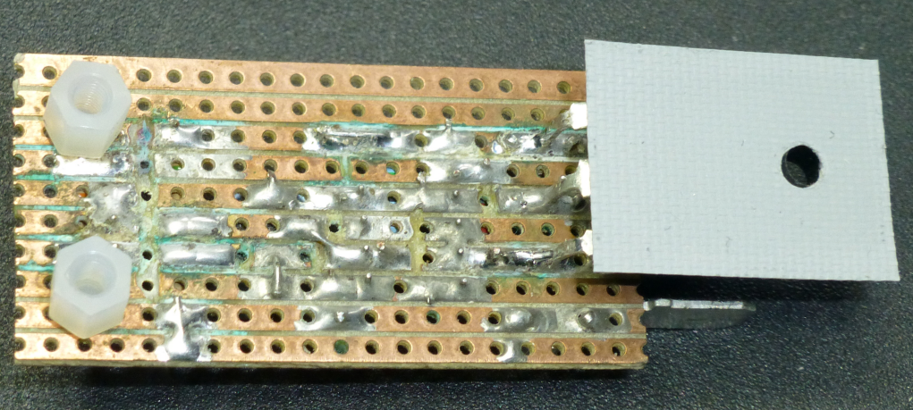
Stripline isn't really rated for 17 amps. Making the holes a little bigger allows the spade connectors to be against the fet pins. Soldering together keeps almost all of the current switched going direct from pin to spade.
Right angle spades I bought have a handy bend in them.
The mosfet pins are not quite the right spacing but near enough with a little bending.
Both need the holes making bigger to fit.
Adjusted mosfet & round file
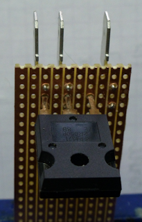
Bigger holes with blades pushed into the stripboard

Bigger holes with blades pushed into the stripboard & mosfet pushed through to the other side.

Mosfet pins pushed through to the other side right next to the blades

First (repeated) pic shows the soldering that goes between the blade & mosfet pin on the 'front' of the stripline board.
And the 90 degree bend to screw the fet to the base plate, you'll need to make a hole.
Do not attach the mosfet to the Alu extrusions it doesn't let the heatpad get the heat out.
And the 90 degree bend to screw the fet to the base plate, you'll need to make a hole.
Do not attach the mosfet to the Alu extrusions it doesn't let the heatpad get the heat out.
The pad is still needed to keep the fet isolated from the baseplate but the top hat isn't as it's built into the mosfet.
Arduino needed a ground reference for the opto so I added a pair of pins for easy plugging into & then joined to a nearby ground.
Hot melt glue toughens up the area from being pulled around.

Second (repeated) pic shows the spacers.
I used 6mm, they were a bit short so use 8mm.
This depends where you solder the mosfet & bend it.
Any questions/mistakes that need fixing just ask.
Enjoy,
Chris
~~~~~

Arthur Wolf
Dec 2, 2013, 3:49:53 PM12/2/13
to ChrisHS, trinitylabs-talk
Awesome work !
Anybody want to throw together a pcb version of this in Eagle ? :)
Anybody want to throw together a pcb version of this in Eagle ? :)
--
You received this message because you are subscribed to the Google Groups "trinitylabs-talk" group.
To unsubscribe from this group and stop receiving emails from it, send an email to trinitylabs-ta...@googlegroups.com.
For more options, visit https://groups.google.com/groups/opt_out.
--
Courage et bonne humeur.

John D
Dec 2, 2013, 3:54:03 PM12/2/13
to trinityl...@googlegroups.com, ChrisHS
+2 on the awesome work! Call it "HeatrBoard" and let's get some made.
Seriously - very nice work!
Seriously - very nice work!
ChrisHS
Dec 2, 2013, 6:18:20 PM12/2/13
to trinityl...@googlegroups.com, ChrisHS
Thanks.
It should also allow those with dual PSUs to isolate one from the other fully.
Use a 1K Ohm resistor for the ground connection to stop it floating too high.
I haven't traced all the power wiring yet.
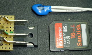
This blue thermoswtches should be small enough to get under the bed.

Chris Cecil
Dec 2, 2013, 8:03:01 PM12/2/13
to trinityl...@googlegroups.com
I would like a way to add a NC relay to the bed circuit so if the FET locks on it will open the relay. Should be easy to add an output to the thermofuse circuit.
I know there is less risk with this circuit but it has always bothered me that we don't have protections of some sort...and large thermofuses are hard to come by.
I know there is less risk with this circuit but it has always bothered me that we don't have protections of some sort...and large thermofuses are hard to come by.
ChrisHS
Dec 3, 2013, 3:37:31 AM12/3/13
to trinityl...@googlegroups.com
Hi,
I think you mean a Normally Open relay so a control wire break switches off the heater rather than the heater protection :-)
Where the OK led is replace it & the resistor with the relay coil & a 1 amp diode reversed across the coil for the flyback current (Diode is essential).
The relay Will die first as it's electro mechanical.
The fet I chose can handle 78 Amps & 400 Watts so it's overrated with a safety margin.
The worst case of half on fet would be only 200W dissipated in the fet & the TC4432 prevents it being in that state.
With that chip removed the on led protects the gate from + & - charged fingers as it will leak to ground before the gates +-30V limit is exceeded.
I've been handling the circuit a lot for the photos & been unable to damage it so far.
I'll see if I have enough bits to make a second set for test ...
Chris Cecil
Dec 3, 2013, 4:30:44 AM12/3/13
to trinityl...@googlegroups.com
I meant NC to avoid cycling when not needed...but the problem is that it would have to pull high. My thought was to put it on the AC lines to the psu to shut it off...but that would require an additional circuit to ensure it worked. Or I guess it would cycle on/off otherwise in fault.
But yes...a proper DC SSR was always desired.
But yes...a proper DC SSR was always desired.
ChrisHS
Dec 3, 2013, 6:16:43 AM12/3/13
to trinityl...@googlegroups.com
For those without electrical knowledge:
SWITCHING MAINS CAN BE LETHAL IF YOU MAKE A MISTAKE.
SWITCHING MAINS CAN BE LETHAL IF YOU MAKE A MISTAKE.
If you are that worried I would want to hear the click every time to know it's still functional.
Keep the modification as I suggested but relay switch mains & add a momentary switch across mains relay to start the psu and power the relay when you release the button.
At overheat the power will latch off in this case to all the other stuff connected to that psu(s) via the relay.
We Must assume that the sensor wires will break as they are being flexed & that fault does not disable the protection from working.

Dave J
Dec 4, 2013, 12:47:48 AM12/4/13
to trinityl...@googlegroups.com
Very nice work. I plan on building this circuit.
Would you give a little more information on where you made your connection to the Arduino?
ChrisHS
Dec 4, 2013, 7:50:38 AM12/4/13
to trinityl...@googlegroups.com
Hi,
Next pin along from D13 is the Ground. D8, 9, 10, 11, 12, 13, Gnd, Aref
Nice picture of the arduino board here http://arduino.cc/en/Main/arduinoBoardMega
Check it with a meter to a known ground pin, it should read close to zero ohms.
Some arduinos have extra socket pins, don't use those !
The ramps doesn't have pins for the extra sockets so still use second from the end on there.
Just don't start counting the unused ones if you look at the side of the boards together.
Chris
~~~~~
ChrisHS
Dec 4, 2013, 6:25:19 PM12/4/13
to trinityl...@googlegroups.com
Read through this all the way before you start !
I forgot to say D8 is the bed heater logic level signal (0 off, 5V on).
So de-solder the A1 trailing wire but don't bother to remove the resistor as it marks where you need to connect to.
The other end of the resistor on the led is also a ground but best left alone as it is easily damaged by heat from cheap soldering irons or a slip.
Using a piece of header pin strip 2 pins long hold by one pin & put the other over D8 on the ramps & solder.
Overlapped rather than one pin atop the other gives more support.
A bit of loose solder placed so you can load the tip of the iron is always helpful when soldering.
The free pin can be soldered to a short bit of wire at one end & the ground pin at the other.
Hot melt glue is just right to make the two new pins firmly attached to the ramps board.
If you make a mistake it can be reheated to make it stick more or be removed if really hot & wiped off with a bit of stiff card.
Depending on your iron wattage you may need to pull the ramps board partly away from the arduino board as the heat will travel down the pin to the other board. D8 should be fine but the ground pin is usually a big pad or plane so is a bit of a heat sink.
The best thing you can get to make soldering work is flux. Rosin cored solder is just to wet the iron. A cheap pot of plumbers flux really does work wonders & lets the solder melt at a lower temperature as it wets the iron really really well.
You are looking for a smooth shiny solder joint that has flowed between the parts you are joining.
I'll have to try the screw terminals with a larger resistance (to cope with 24V) to see if works as well, should do but I'll test it before I suggest it for others.
That would be for a manufactured HeatrBoard without user soldering :-)
Reply all
Reply to author
Forward
0 new messages