help with 3 wire serial including gnd and power for VFD

Kris
Hello,
I'm hoping you can save me a bit of time and troubleshooting.
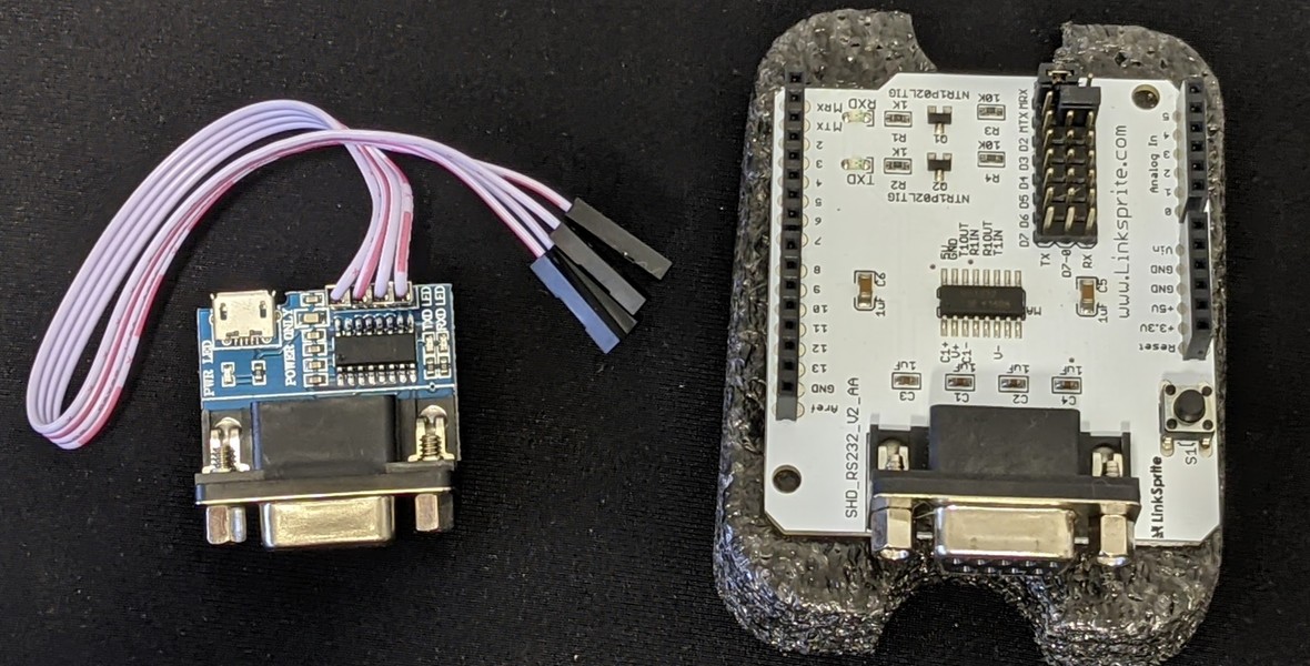
I have this very nice VFD from an old POS terminal

[image of front of circuit board]

[image of rear of board showing rj45 socket]
it has no googleable model numbers and it has a single rj45 connector that terminates in a db9.
When i disassemble the db9 shell it reveals only three conductors go to the device from the DTE.

[female/socket db 9 showing rear pins]
There are no other cable connections on the display.
I have made the following assumptions:
It uses serial (as almost all older POS terminals do)
It is using industry standard wiring (from memory it was plugged into an AT motherboard, OEM, but not custom).

Given those assumptions that would mean that it has the following pinout:
1 Carrier Detect
2 Rx
3 Tx
4 Data Terminal Ready
5 Gnd
6 Data Set Ready
7 Request to Send
8 Clear to Send
9 Ring
And has the following wiring
1 Carrier Detect connected to Data Terminal Ready
2
3 Tx
4 Data Terminal Ready connected to Carrier Detect
5 Gnd
6
7 Request to Send
8
9
There is a power switch on the device and when i meter it, it has a 7ohm resistance to the ground pin (5) and no connection to other pins.
The ic nearest the power switch is an ATMEL934 which is a Time code Receiver which runs on 5v.
There's a pleasing 8 bit microcontroller on there called the TS80C32X2 (datasheet) which is also 5v.
So i reckon the device runs on 5v but i'm not sure about that.
Question is:
How do i connect this to an arduino or a raspberry pi? what pin is power, what pin is ground and don't i need tx and rx for serial?
Thanks,
Kris

Andrew Larkin
Your PCB photos didn’t come through…
--
You received this message because you are subscribed to the Google Groups "Robots & Dinosaurs" group.
To unsubscribe from this group and stop receiving emails from it, send an email to sydney-hackspa...@googlegroups.com.
To view this discussion on the web visit https://groups.google.com/d/msgid/sydney-hackspace/53496faa-2470-b51c-a58f-36c5e5406792%40sleepingplanet.com.
Kris
i can't send through an email with the url as the google spam filter eats it.
photos are
https://
and then add
/LgPkF7cndfTMzNcL8
To view this discussion on the web visit https://groups.google.com/d/msgid/sydney-hackspace/004701d7ac30%2454088090%24fc1981b0%24%40arcadius.com.au.
Kris
ok, pin 7 has zero ohm to the power switch.
pin 5 (gnd) has 7 ohm to the other side of the power switch.
so it looks like i have power....
hmmmmm what if i throw caution to the wind....
wooo
success!
it's 5v, runs at about 300mA, peaks at 500.
going to play with an arduino that i don't mind exploding and see if i can work it without a max232 module.
Andrew Larkin
Kris
thanks Andrew, will do.
Is that because i need a negative voltage to transmit a '0'?
To view this discussion on the web visit https://groups.google.com/d/msgid/sydney-hackspace/614573d1.1c69fb81.3040c.5b91SMTPIN_ADDED_MISSING%40gmr-mx.google.com.

Matt Callow
To view this discussion on the web visit https://groups.google.com/d/msgid/sydney-hackspace/225b1116-959f-b648-9006-8fef4f5b52e5%40sleepingplanet.com.
Kris
To view this discussion on the web visit https://groups.google.com/d/msgid/sydney-hackspace/004701d7ac30%2454088090%24fc1981b0%24%40arcadius.com.au.

John Tocher
Kris
Thanks John,
Once i powered up the display it told me the baud rate during
boot, so that was handy! (9600)
I have a max232 module but i'm lazy and was going for simple.
It's going to be run from an esp32 which has additional fun since
it's a 3v device...but in theory, High on 3.3v is enough for a
high on a 5v system. And there's no return signal so i should be
ok.
I'm toying with the idea of simply soldering the gpio of the esp32 to the output pin of the sipex chip thus bypassing rs232 entirely.
However looking at the datasheet, whilst the sipex chip is designed for up to -15v input for low input, it says it's happy with +1.2 or lower. So might work without a shifter anyway (as long as i invert the signals since rs232 is inverted).
https://pdf1.alldatasheet.com/datasheet-pdf/view/45915/SIPEX/SP232ACP.html
Page 2
the final project is a display for the kitchen, run by an esp32 which is connected to Home assistant and an ntp server.
It will display time, data, outside temp, rainfall forecast over next 24h and the current power consumption for the house.
oh, and if i've left the garage door open as i often do.
:0)
To view this discussion on the web visit https://groups.google.com/d/msgid/sydney-hackspace/d7a00feb-8150-4917-b1d1-7d6def8c3b54n%40googlegroups.com.
Kris
ah thanks!
To view this discussion on the web visit https://groups.google.com/d/msgid/sydney-hackspace/CAO%3Dbg_Uf4Xxqe%3DkWCLY%3D2YnZL1gLDFeWp7_-0mp5yd9GzJ%3DOcw%40mail.gmail.com.

Thomas Squires
To view this discussion on the web visit https://groups.google.com/d/msgid/sydney-hackspace/e8ea28f3-1738-7ae8-d6e4-8966d8ccd2cd%40sleepingplanet.com.