Get Output Signal From SpiNNaker

李文博
We can now transmit eDVS packets to the spiNNaker board, but the data sent via the FPGA did not cause any neural spikes on the platform and I do not know how to get the output signal(e.g. the neuron firing info) from the spiNNaker board. Because the ultimate goal of my project is to drive a motor based on the output signal from the board so it seems to be a must. I am wondering if it is possible to use the 34-pin GPIO port on the board. And I went through some tutorials of spynnaker external device plugin: https://github.com/SpiNNakerManchester/SpiNNakerManchester.github.io/wiki/2015.004%3a-Little-Rascal-%3a-2.2-Extracting-data-from-a-simulation-on-a-SpiNNaker-machine-in-real-time which mainly demonstrates how to do simulations with artificially generated data instead of real data from sensors(eDVS). I am puzzled now how can I make the neuron population fire with external device input and is there an alternative way of extracting simulation data besides using the ethernet port?
Thanks for your time! Looking forward to your response!
Wenbo

Andrew Rowley
Hi,
In order to get packets to the neural models, the routing needs to be set up. In our software, we support this through the concept of a Virtual Population, which is then connected to the real population via a projection (or in terms of the graph, there is a virtual vertex connected to the real vertex via an edge). There are some examples of these in the sPyNNakerExternalDevicesPlugin e.g. there is a retina model here:
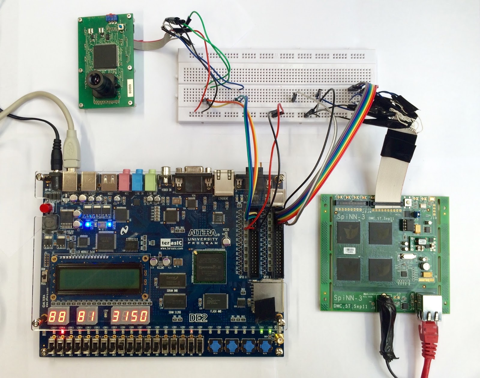
The key features of this device are the connected_to_real_chip_x, connected_to_real_chip_y and connected_to_real_chip_link_id properties, which tell the system the actual physical connection of this device to the board. The two SpiNNaker Links on the board that you show in your picture are actually physically connected to links on the chip, and it is these links that are being described in the above. On the SpiNN-3 board, one of the connections connects to link 3 on chip 0,0 and the other connects to link 0 on chip 1,0. I think you are using the second of these.
The other feature of the device is the description of the keys that will be sent down the link, in terms of a (32-bit) base key and a mask that will cover all of the keys. Note that our neuron models expect only a 32-bit key without a payload; if you send packets with a payload, the models will ignore them. In the example, the base key is based on the virtual chip x and y coordinates. It is not essential that this is the case; you can choose any base key you like, as long as this is the key with which each spike is being sent. The mask should be set such that base_key & mask == base_key, and that for any actual key sent, key & mask == base_key.
Hope this helps,
Andrew :)
--
You received this message because you are subscribed to the Google Groups "SpiNNaker Users Group" group.
To unsubscribe from this group and stop receiving emails from it, send an email to
spinnakeruser...@googlegroups.com.
To post to this group, send email to
spinnak...@googlegroups.com.
For more options, visit https://groups.google.com/d/optout.
李文博
Andrew Rowley
Hi,
If you are still having issues, you could verify that the routing tables are set up correctly. In ybug, you can switch to the chip that you expect to be receiving the packets:
sp x y
where x and y are the coordinates of the chip that you expect packets to be received at. You can then look at the routing tables:
rtr_dump
If this contains the routes that you expect, and you still don’t see any packets being received at the receiving core, then either you are not sending with the expected keys, or else you are adding a payload (i.e. sending all 72 bits rather than just 40 bits for each packet). If you are adding a payload, the packets will be ignored by our neuron models, so you wouldn’t see any activity even if you have everything else set up correctly.
As a final debug step, you could set up a simple binary for spinnaker that simply receives packets on a core. You could then set up a routing entry on a chip to forward all multicast traffic to that core. This way you could see every packet arriving (although note that at high data rates, printing output in the multicast receive interrupt handler will likely result in some packets being dropped).
Andrew :)
--
