Help flashing Sonoff RF R2
Skip to first unread message

Peter Houston
Oct 16, 2018, 5:22:34 AM10/16/18
to SonoffUsers
I have an R2 version of the Sonoff RF and can’t get it to go into flash ready mode to accept Tasmota. The board seems to have a different layout than that on the wiki page and the RF board is attached horizontally not vertically like the original. Haven’t had any luck with just holding down the button during powering. Do you still need to separately bridge GPIO 0 to ground? There’s no R21 like the original. Any help would be appreciated. Thanks

Phil
Oct 16, 2018, 2:49:51 PM10/16/18
to SonoffUsers
I dont have a sonoff rf v2 but if the button is not wired to gpio0 grounding gpio0 to start up the device in the programmable mode will be necessary some other way.
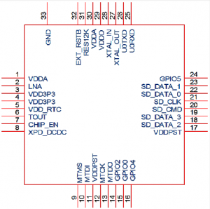
the itead wiki isnt upto date with this pcb so perhaps check out specs and relevant pdfs for the actual soc and soldering a jumper lead to a ground point and a manual touch of the relevant soc leg under a magnifying lamp(i would need one) might be the fall back option, unless anyone can point out a more accessible point?
looks like 2nd pin in from the right on the bottom edge of the soc?
Peter Houston
Oct 17, 2018, 9:30:49 PM10/17/18
to SonoffUsers
Hi Phil
Thanks for the quick reply and chip diagram. I had actually tried bridging it's contact to ground but not sure if it's my non-existent soldering skills or something else. I assume you would still need to hold down the button on the board during powering as well? The other problem with the new design is the RF board mounted horizontally mostly covers the ESP8266 chip so it's impossible to access the GPIO0 directly until someone more savvy than me figures out an easier contact to bridge. Guess I'll just have to wait to see as more people get the R2 what the answer is or maybe return the ones I bought for the Sonoff basic version.
Phil
Oct 17, 2018, 10:00:19 PM10/17/18
to SonoffUsers
No, No additional button press should be necessary if your grounding gpio0 with another method.
if you have had no joy? try confirming the chip orientation with respect to the diagram with a continuity check between the gnd vcc tx and rx pin holes on the programming header with the legs on the chip, if they all check out you have definitely identified the gpio0 leg, and if not, check again after rotating 90 degrees... and if all 4 x tests fail, ive bum steered you to a bad diagram.. ooops!
if your having problems touching a chip leg and only that leg, consider soldering a pin or needle to the end of your connecting wire for excuse the pun 'pin point accuracy' and some traction when connected
Peter Houston
Oct 18, 2018, 7:32:52 PM10/18/18
to SonoffUsers
Thanks again for the help Phil. I have had a closer look at the chip on the Sonoff RF R2 and it is actually an ESP8285. I had to remove the horizontally mounted RF board covering it (and I think I've killed the Sonoff RF I did this to).
From the schematics I have found for the 8285, it has a similar layout. Using the Wifi antenna and LNA as orientation, I think I have found GPIO0 which appears to connect through the board and to IO2 next to the other main pin holes. I've attached a couple of pics to make this clearer (forgive my butchering of the board - hopefully the sacrifice makes it easier for the others as I don't want to try and remove the RF boards again). I have tried numerous times and multiple ways (with PlatformIO and Atom on Mac and FlashESP8266 on PC as well as various firmwares).
Seems like Itead and Sonoff are trying to make this harder.
Peter Houston
Oct 18, 2018, 8:05:06 PM10/18/18
to SonoffUsers
Success! I obviously need reading glasses.
So my markup of the the underside in the message above is wrong. GPIO0 actually connects to K_P which goes to the RF board. That can be grounded to a neighbouring pin. I have attached corrected photos.
Thanks again Phil for all the guidance. Hopefully this helps people with the new R2 boards.
Cheers
Pete
Phil
Oct 19, 2018, 4:41:41 PM10/19/18
to SonoffUsers
Result! Could be worth adding your pics and tips to the wiki for future reference..
Peter Houston
Oct 20, 2018, 1:17:14 AM10/20/18
to SonoffUsers
Good idea. Added it to https://github.com/arendst/Sonoff-Tasmota/wiki/Sonoff-RF

Johnathan Wee
Oct 24, 2018, 3:32:50 AM10/24/18
to sonof...@googlegroups.com
On Saturday, 20 October 2018 13:17:14 UTC+8, Peter Houston wrote:
Good idea. Added it to https://github.com/arendst/Sonoff-Tasmota/wiki/Sonoff-RF
Hi Peter,
Could you resend your pics and instructions for flashing the R2 version again?
I just found out mine are also the newer R2 version
Update: no worries, it was my pfsense blocker that cut out all the diagrams. I actually find this new R2 version easier to flash since the ground point is so obvious now
Peter Houston
Oct 24, 2018, 6:05:50 AM10/24/18
to SonoffUsers
Good you figured it out. For others that come across the group my photo showing where to ground GPIO0 (I just used a flathead screwdriver) is here:

Peter Randall-Cook
Nov 17, 2018, 3:55:51 AM11/17/18
to sonof...@googlegroups.com
Hi All,
OAP from the UK.
Pictures on Sonoff RF - V2
Flashed all OK using ESPTool, ONLY held the toggle/Black button down to trigger upload status.
Will try with my second Sonoff - V2 board and see if its the same.
Image RF3 shows the GND and K_P pins which I did NOT use!
Peter
Johnathan Wee
Jan 11, 2019, 12:58:26 AM1/11/19
to SonoffUsers
I wish to place a DS18b20 sensor with this new version of Sonoff RF.
Can anyone suggest how and where to place the vcc, 3.3v and ground wires?

Michal Kuzak
Jan 18, 2019, 8:44:10 PM1/18/19
to SonoffUsers
I have tried to solder the two pins together. Pressed Button , plugged in USB .. no luck ..
Trying to back up the original firmware
esptool.py -p com10 -b 460800 read_flash 0 0x100000 sonoff_original_firmware.bin
esptool.py v2.6
Serial port com10
Connecting........_____....._____....._____....._____....._____....._____....._____
A fatal error occurred: Failed to connect to Espressif device: Timed out waiting for packet header

Any advice ?
Thanks

George Ioakimedes
Jan 18, 2019, 9:22:54 PM1/18/19
to SonoffUsers
This looks like you either don't have a good connection or GPIO0 isn't being held low. Start with a simpler ESPTOOL command like esptool.py -p com10 flash_id and confirm you can talk to the chip first.
Reply all
Reply to author
Forward
0 new messages