Confirmed working: Joywell Power Strip

2,055 views
Skip to first unread message

gmac42

unread,
Apr 24, 2018, 4:43:55 PM4/24/18
to SonoffUsers

Hi everyone,

I just successfully flashed Tasmota on a Joywell Power Strip (4x Socket, 1x 4-Port-USB power supply).
See: https://www.amazon.de/Steckdosenleiste-Steckdose-App-Steuerung-Bedienung-Assistant/dp/B079C1HPSK

It contains a TYWE2S-Module, which in turn contains an ESP8285.
Flashing was a bit cumbersome because I had to desolder the whole module to get to the GPIO0 test point. But otherwise everything worked fine.


This works like a charm now.

However, if anyone knows a similar product that is easier to flash, I'd be glad for a hint! :-)


Best regards

Gert

gmac42

unread,
Apr 24, 2018, 4:47:36 PM4/24/18
to SonoffUsers
Oops, the formatting of the images got messed up, sorry for that.

leg...@googlemail.com

unread,
Mar 21, 2019, 4:18:30 PM3/21/19
to SonoffUsers
I can confirm this still works. Its a bit ugly to get the package out and back in, but it works.

Tried to figure out if we can flash it via OTA, but without taking the original app apart i don't see how. :(

Phil

unread,
Mar 21, 2019, 6:51:14 PM3/21/19
to SonoffUsers

Hi

Checking the link you provided to amazon-de, And in the text by the pics at the top it seems to mention a 'smart-life' app??
This would indicate its an ideal candidate for an OTA flash with the tuya-convert method discussed elsewhere in here, 
fwiw i have flashed a similar 4xsocket device with 4x yk sockets and 4x usb ports OTA with success ..#

sorry to be late to the party with the news for this device, but it should make the next one  Doddle to flash ;)

leg...@googlemail.com

unread,
Mar 22, 2019, 3:17:42 PM3/22/19
to SonoffUsers
The problem is, that this device does not show a SSID when booting up the first time (at least mine did not) so i had no idea how to connect to the device without taking the app apart.

Since i am new to this topic i might have not seem something obvious. I am planning on buying 2 more that look similar why i guess its the same thing but with another name printed on it, then i can try again.

This is what you where talking about?

Michael Ingraham

unread,
Mar 22, 2019, 3:30:46 PM3/22/19
to leg...@googlemail.com, SonoffUsers
This is the best latest method - https://github.com/ct-Open-Source/tuya-convert

And when you power up after a successful flash, you should see a 'sonoff-xxxx' SSID on your network to connect to and then visit 192.168.4.1 to configure the device.

Tuya has started to closed the hole that allows the OTA flash. If you use Tuya-OTA, it started by asking you to pair to the Smart Life app first. The problem with that today is that if you do, the app will try to update the existing firmware thus closing off the OTA method. Tuya-convert didn't and doesn't require Smart Life pairing so, until Tuya ships with the new firmware at least, Tuya-convert ought to get it flashed. Plus, the Tuya-convert guys are working on a workaround to Tuya's workaround ;-)

Michael Ingraham
Spartanburg, SC


--
You received this message because you are subscribed to the Google Groups "SonoffUsers" group.
To unsubscribe from this group and stop receiving emails from it, send an email to sonoffusers...@googlegroups.com.
For more options, visit https://groups.google.com/d/optout.

leg...@googlemail.com

unread,
Mar 22, 2019, 3:37:16 PM3/22/19
to SonoffUsers
This is the best latest method - https://github.com/ct-Open-Source/tuya-convert
Thanks for the Link! :)

And when you power up after a successful flash, you should see a 'sonoff-xxxx' SSID on your network to connect to and then visit 192.168.4.1 to configure the device.
Yeah mine behaved like this, i meant the device with the original firmware. But after reading the source the c't provided, i saw that it seems to work by broadcasting packages via w-lan and then the device picks then up to configure itself. This was my missing Link. :)


Thanks for the answer! :D

leg...@googlemail.com

unread,
Mar 23, 2019, 7:43:00 AM3/23/19
to SonoffUsers
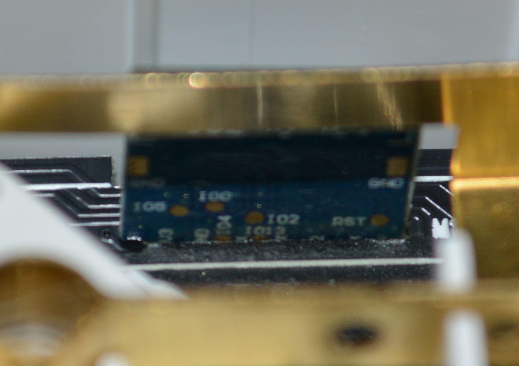
  • 1,2 -> both sides of the TYWE2S
  • 3,4 -> both sides of the main circuit that carries the TYWE2S, Relais and power delivery
  • 5,6 -> both sides of the USB curuit in case someone is interrested in this
  • 7    -> the board that carries the socket LEDs
  • 8    -> i recomment to add some hot glue because the hot wires where touching the netral rails and the LED wirestrip did touch the protection rail and was already slightly damaged
Specially Picture 8 should hint, that everyone who buys this Power Strip should open is once to at least secure the wires with hot glue. :)

leg...@googlemail.com

unread,
Mar 23, 2019, 7:51:50 AM3/23/19
to SonoffUsers
i accidentally deleted the head of my message...

i created some pictured of my device just in case someone might find them useful.

Here is the link for the complete folder:

leg...@googlemail.com

unread,
Mar 27, 2019, 5:19:40 PM3/27/19
to SonoffUsers
OTA Flashing with tuya-convert works just fine! :)

I also tested the Powerstrip by Koogeek, i prefer this one over the Joywell since its cheaper but looks like a better quality product.
Additionally this one can be flashed by soldering without removing the TYWE2S. (See my attachments)

1.jpg
2.jpg

Phaeton

unread,
Jun 18, 2019, 4:04:20 PM6/18/19
to SonoffUsers
Hi, I tried to use tuya-convert to do a OTA update on the Koogeek Strip. I cannot get this to work. Yo mention you can flash  this without removing the TYWE2S. How did you reach the chip to solder wires? I get stuck with the ground,cannot seem to be able to remove it. 

Op woensdag 27 maart 2019 22:19:40 UTC+1 schreef leg...@googlemail.com:

Ronny Kramer

unread,
Jun 19, 2019, 3:06:26 AM6/19/19
to SonoffUsers
Did you follow the instructions of tuya-convert?
- Just checking that you really connected a second device to the wireless access point created by tuya-convert as well as followed the described order.
Hint: I also required a couple of tries until it worked, as my usb-wlan-stick did not like being an access point and the firmware crashed randomly after a couple of minutes. (Once i randomly hit a try where it did not crash it worked for hours...)

Could you provide a picture from the inside of your strip?
-Depending on the model the daughter board is either not accessible if its located right next to a relay or fairly easy to access if its located in the center of the socket as in the newer revision seen in my last post.

Removing the daughter board required to absolutely clean all solder points or else it can't get pulled out as it has a very tight fit.

Phaeton

unread,
Jun 19, 2019, 4:30:33 PM6/19/19
to SonoffUsers
I followed all instructions to the letter on a pi3b. I managed to flash a few devices this way, but i have two of the koogeek ones which do not respond. I get a 'connection refused' error. Research on github showed these devices have a newer firmware which prevents the flash. Thats why i look for an alternative; flashing with soldering.

My strip looks exactly as your 1.jpg image. Last night, after posting my message, I found some documentation on the chip in the koogeek. I now know how to connect wires and flash. But space is a bit tight and I couldnt easy remove the daughter-board. Did you manage to take out the board or did you manage to solder it without taking it apart? If the first: could you throw in a hint? If the second: i guess i have to step up my soldering game ;)

Ronny Kramer

unread,
Jun 19, 2019, 4:44:34 PM6/19/19
to SonoffUsers
I did all 3 things. My first try with the joywell was flashed by unsolder the daughter board, this worked well if you have a manual vacuum suction pump. (i don't know the english term, sorry)
The other devices got flashed using tuya. One of them got bricked when i accidentally tried to update it without using the update firmware first.

So to reflash the device in this state i dismantled it. Meaning i took all boards out and then there was enough room to solder everything.
- Just be carefull with the id0, this is pretty fragile and i accidentally ripped of the solder contact when i tried to put everything back together without desoldering it first ...

So yes you need to remove the boards from the strip, but you don't need to separate the 2 boards. - At least for me it worked without unsoldering the daughter board.

Phaeton

unread,
Jun 20, 2019, 12:18:59 AM6/20/19
to SonoffUsers
Clear! One last question: how did you remove the ground parts to remove the boards? I cannot get Them out of the socket and am afraid i use to much force and break something

Phaeton

unread,
Jun 20, 2019, 4:57:07 PM6/20/19
to sonof...@googlegroups.com
An update; I flashed the remaining power strips. Some tips and answers to my questions above (for people who came here looking for help.

The ground can easily be removed if you take of the 4 white caps holding it in place (i thought this was not possible and this assumption got me stuck). after this you can remove the screws and lift up the whole board for easy acces. 

you can then solder the chip. You can use this document as a reference:

Connect 3.3v and ground
connect the tx to the rx of the serial adapter
connect the rx to the tx of the serial adapter

then you are good to go and flash the module.

Ronny, thanks for you help along the way!

Op donderdag 20 juni 2019 06:18:59 UTC+2 schreef Phaeton:

Ronny Kramer

unread,
Jun 21, 2019, 3:04:52 AM6/21/19
to SonoffUsers
Nice remarks!

Now i am curious what you mean with ground? The ground in sockets?
It sounds like you are tacking apart the sockets, i do not recommend to do this, as it sounds very likely to break something.
-> Here it is easier to simply remove the sockets them self with a slight push from the outside to the inside, you don't need much force and they will simply plop out.

Sorry that i did not get your problem, when read your post!

As remark from my side all GPIOs except the ID0 are also available on the pins the button of the daughter board. If you use these its easyer to solder everything, as the OP proposed.


You are welcome! :)


Paul Annekov

unread,
Nov 22, 2020, 12:20:11 PM11/22/20
to TasmotaUsers
Please, help me to solve the problem with my Zeoota ZLD-44EU-W (it's exactly the same as Joywell, just different whitelabel) power strip. When I plug it, it flashes with LEDs (on some sockets and on the power button) in an infinite loop and I hear the clicks of relays. It seems that power is on/off in a loop for an entire power strip. It does not connect to wifi and does not create a hotspot either.
This is how it looks when assembled: https://youtu.be/Op4vQQHQZFc
and disassembled: https://youtu.be/73cRfcy0nbE

How I got to this:
I decided to upgrade to Tasmota via tuya-convert. The flashing was successful, a backup was created, the power strip created a hotspot, I set up a connection to my home wifi network, unplugged it and put it back in. After that, he entered this "loop".

What have I tried:
1. I tried both reset options at https://tasmota.github.io/docs/Device-Recovery/ - no effect at all. It does not respond to pressing the shutdown button and plug it in/out 7 times also does not change anything
2. I've unsoldered the tywe2s chip, connected it to a serial to ttl adapter (not in programming mode) - everything works. The chip is connected to the wifi network, the web interface is available.
3. Soldered back, turned on the power strip - same loop, nothing works.
4. In soldered state, I connected it again to serial to ttl, now in programming mode and flashed it to the original firmware, which was backed up by tuya-convert. Plug in - no change.
5. I returned the firmware to Tasmota - no changes.

It looks like I broke something on the board of the power strip itself, but I can't figure out what.  

пятница, 21 июня 2019 г. в 10:04:52 UTC+3, leg...@googlemail.com:

Philip Knowles

unread,
Nov 22, 2020, 3:07:55 PM11/22/20
to Paul Annekov, TasmotaUsers

Do you see anything on the serial port using a terminal programme?


Regards


Phil K


Sent from Mail for Windows 10

--
You received this message because you are subscribed to the Google Groups "TasmotaUsers" group.


To unsubscribe from this group and stop receiving emails from it, send an email to sonoffusers...@googlegroups.com.

Paul Annekov

unread,
Nov 22, 2020, 3:42:30 PM11/22/20
to TasmotaUsers
Yep, I see a normal boot log:

00:00:00 WIF: Connecting to AP1 SR Channel 1 BSSId B2:69:F4:14:62:35 in mode 11N as tasmota_AFC80A-2058...
00:00:01 WIF: Connected
19:25:16 HTP: Web server active on tasmota_AFC80A-2058 with IP address 192.168.0.31
19:25:17 RSL: tele/tasmota_AFC80A/INFO1 = {"Module":"Sonoff Basic","Version":"9.1.0(tasmota)","FallbackTopic":"cmnd/DVES_AFC80A_fb/","GroupTopic":"cmnd/tasmotas/"}
19:25:17 RSL: tele/tasmota_AFC80A/INFO2 = {"WebServerMode":"Admin","Hostname":"tasmota_AFC80A-2058","IPAddress":"192.168.0.31"}
19:25:17 RSL: tele/tasmota_AFC80A/INFO3 = {"RestartReason":"Power On"}
19:25:17 RSL: stat/tasmota_AFC80A/RESULT = {"POWER":"OFF"}
19:25:17 RSL: stat/tasmota_AFC80A/POWER = OFF
19:25:20 QPC: Reset
19:25:21 RSL: tele/tasmota_AFC80A/STATE = {"Time":"2020-11-22T19:25:21","Uptime":"0T00:00:09","UptimeSec":9,"Heap":27,"SleepMode":"Dynamic","Sleep":50,"LoadAvg":19,"MqttCount":0,"POWER":"OFF","Wifi":{"AP":1,"SSId":"Guest","BSSId":"B2:69:F4:14:62:35","Channel":1,"RSSI":66,"Signal":-67,"LinkCount":1,"Downtime":"0T00:00:03"}}

Also, I've just checked the power on tywe2s module when power strip plugged and it's not 3v3, it's much smaller and random (https://youtu.be/4xlS8PgBKD8). So there is something wrong before chip.
воскресенье, 22 ноября 2020 г. в 22:07:55 UTC+2, knowles...@gmail.com:

Philip Knowles

unread,
Nov 22, 2020, 4:45:41 PM11/22/20
to Paul Annekov, TasmotaUsers

It looks like voltage is the problem but don’t see how OTA conversion could cause that. I’d finish the setup with you own power on it just in case being in Basic is causing a problem (unlikely though)

Reply all
Reply to author
Forward
0 new messages