Sonoff SV LED dimmer project help

pete c


Mosquitto control


mike2nl

Philip Knowles
I think this is going to be difficult.
The dimmer will almost certainly use the pot to vary between 0 and 12V to achieve the dimming. I don’t think PWM will work well enough to give you a consistent voltage at the pot – it may do with a transistor output rather than a relay.
You could use an ESP-12 with some sort of digital to analogue converter and use all of the outputs to give you 256 steps of dimming
Good luck and I hope you prove me wrong!.
Regards
Phil K
Sent from Mail for Windows 10
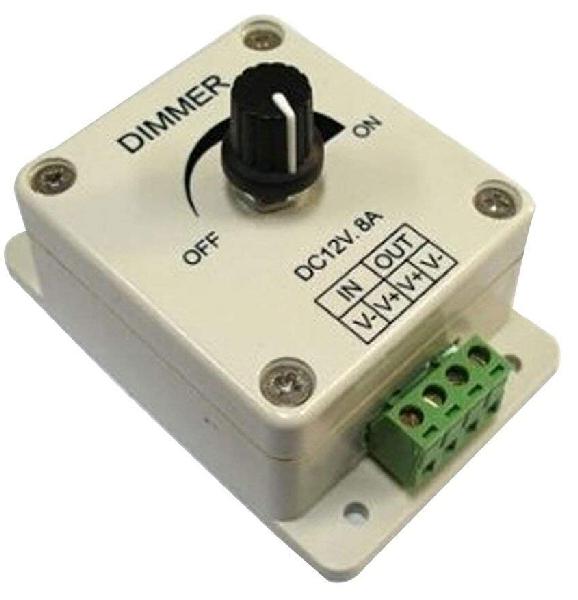
Trying to figure out how to do this with a SonOff SV and a dimmer circuit from a $2 Ebay dimmer.
I think it should be easy.
Looking for suggestions here.
--
You received this message because you are subscribed to the Google Groups "SonoffUsers" group.
To unsubscribe from this group and stop receiving emails from it, send an email to sonoffusers...@googlegroups.com.
For more options, visit https://groups.google.com/d/optout.
pete c
what do you want to do?- switch on/off or- dimming
I don't understand your question.on/off via the relais ordimming via PWM to GPIO pin.
pete c


D472A N-Channel SDMOSTM POWER Transistor

78L05 5V 100mA Voltage Regulator

You could use an ESP-12 with some sort of digital to analogue converter and use all of the outputs to give you 256 steps of dimming
Have Arduino nanos here but want to keep the little project box to using only the Sonoff SV and dimmer circuit board.

Phil
pete c
Philip Knowles
You could get an 8 step dimmer by creating a voltage divider with 7 resistors in series (across the pot +v and 0v) and use 8 transistors each controlled by an output from an ESP-12 which would feed into the pot wiper. Each transistor would give you an increased voltage at the pot. The reality is that you wouldn't need 8 steps perhaps only 3 or 4. Off would be no outputs on then say 25, 50, 75 and 100%. You could do that on a quite small piece of Veroboard.
Phil K
--
You received this message because you are subscribed to the Google Groups "SonoffUsers" group.
To unsubscribe from this group and stop receiving emails from it, send an email to sonoffusers+unsubscribe@googlegroups.com.
pete c

Mark Roles
If you use a ESP8266 module that has an analog pin readily accessible on it (like the D1 mini) you can enable it by commenting out this line of code "#define USE_ADC_VCC " in the in the file user_config.h.
pete c
