Sonoff 1ch inching 5/12v and Tasmota
2,731 views
Skip to first unread message

pa...@fourfoot.net
May 10, 2017, 7:56:06 AM5/10/17
to SonoffUsers
Has anyone managed to get the Sonoff 1 channel inching 5/12v switch working with Tasmota?
I've figured out which pins are for programming, however after successfully (according to Atom) uploading tasmota firmware, the switch just loops, toggling the relay every 1 second and doesn't connect to WiFi. Same result on two switches.
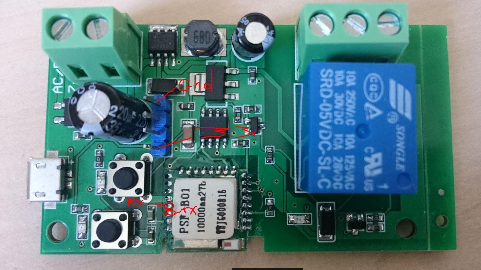
Photo of the board attached, it's different to the one shown on ITEAD's site (where I purchased from) - so are they sending out a new version which isn't compatible with tasmota? I note mine says PSF-B01 on the module, whereas the one shown on their site is PSA-B01
I've figured out which pins are for programming, however after successfully (according to Atom) uploading tasmota firmware, the switch just loops, toggling the relay every 1 second and doesn't connect to WiFi. Same result on two switches.
Photo of the board attached, it's different to the one shown on ITEAD's site (where I purchased from) - so are they sending out a new version which isn't compatible with tasmota? I note mine says PSF-B01 on the module, whereas the one shown on their site is PSA-B01

Pascal
May 10, 2017, 2:29:37 PM5/10/17
to SonoffUsers
That's a very tricky switch.
I had the same problem with the old model.
I chose ElectroDragon and that does work with that model.
Inching mode I did not get it work with Tasmota and this module.
I had the same problem with the old model.
I chose ElectroDragon and that does work with that model.
Inching mode I did not get it work with Tasmota and this module.


Pasquale Nardelli
May 19, 2017, 5:24:51 PM5/19/17
to SonoffUsers
Hello Paul!
Will you share pins configuration for entering bootloader mode? I can't seem to figure it out
Thanks,
Pasquale
Paul C
May 19, 2017, 6:50:17 PM5/19/17
to SonoffUsers
Hi,
See the photo attached to the first message in this thread. +3.3 and GND are available on the header if you solder in some pins. TX and RX you have to connect directly to the daughter board with the chip as the header pins aren't connected.
See the photo attached to the first message in this thread. +3.3 and GND are available on the header if you solder in some pins. TX and RX you have to connect directly to the daughter board with the chip as the header pins aren't connected.
To enter programming mode hold down the button closest to the capacitor whilst applying power, then release after 2 seconds.
Paul C
May 19, 2017, 6:52:18 PM5/19/17
to SonoffUsers
As a side note, I gave up with this switch - ended up using a sonoff sv and programmed my mqtt broker to immediately respond to the power on broadcast with a power off command - so everytime it switches on, it gets told to immediately switch off, replicating how the inching switch would work.
Pasquale Nardelli
May 21, 2017, 10:21:47 AM5/21/17
to SonoffUsers
Thank you!

Jayden Russell
May 25, 2017, 8:24:07 PM5/25/17
to SonoffUsers
I am using the SV as an inching switch, user_config.h has a relay pulse time
Turn relay on and off after 1 second, enough to emulate garage door button press.
#define APP_PULSETIME 10 // [PulseTime] Time in 0.1 Sec to turn off power for relay 1 (0 = disabled)
Paul C
May 26, 2017, 5:00:50 AM5/26/17
to SonoffUsers
That sounds perfect - I'll have to give it a try later. Not sure how I managed to miss that option, I've been through the config hundreds of times!
Thanks
Thanks
Message has been deleted

Jim S
Jul 2, 2017, 2:08:13 AM7/2/17
to SonoffUsers
I have received SV for the garage door. I was curious if SV needs to be powered from 5V (in inputs). Then connect the wires from the garage switch to the output terminals of SV. Or can the SV be powered from garage wires only, if so do you close the output terminals with a wire?
Thanks in advance for any information.
Paul C
Jul 4, 2017, 6:06:44 PM7/4/17
to SonoffUsers
That depends on the garage door. Mine uses a 24v control signal to open/close/stop the door, so I have my sonoff powered from a separate 12v circuit (with other systems in my garage). The sonoff relay then has 24v from the opener to the common terminal and the return to the opener on the NO contact, so when sonoff is operated for a second this sends a 1 second 24v pulse to the opener making it open/stop/close.
Jim S
Jul 4, 2017, 7:27:53 PM7/4/17
to SonoffUsers
Thank you for your response. So, at the input terminals, you have disconnected the jumper and providing 12 V power. At the output ( - , + ), you hook up the two wires from the garage door. In the bottom image, there is an option to remove resistor and to power it separately. I am trying to figure out whether the garage door wires go into input or output terminals without messing up. Initially, I had sonoff 1ch inching but I am not able to flash it with tasmota firmware after numerous attempt. I see you have all been able to use SV for inching process.

Paul C
Jul 5, 2017, 3:31:24 AM7/5/17
to SonoffUsers
I have isolated mine (as per the last image - removing the resistors). 12v is applied to the lower set of pins as in the image.
I then have the 2 wires from the opener connected to the input+ and output+. Nothing connected to the input- and output- as if you follow the traces on the board you'll see they are just directly connected and don't go through the relay.
I then have the 2 wires from the opener connected to the input+ and output+. Nothing connected to the input- and output- as if you follow the traces on the board you'll see they are just directly connected and don't go through the relay.
Jim S
Jul 5, 2017, 8:11:48 PM7/5/17
to SonoffUsers
I get it now. Thanks again for your time in explaining and providing the information.
Reply all
Reply to author
Forward
0 new messages