Help with AM2302 sensor

Alex

Philip Knowles
Sent: Thursday, July 8, 2021 6:13:12 AM
To: TasmotaUsers <sonof...@googlegroups.com>
Subject: Help with AM2302 sensor
You received this message because you are subscribed to the Google Groups "TasmotaUsers" group.
To unsubscribe from this group and stop receiving emails from it, send an email to sonoffusers...@googlegroups.com.
To view this discussion on the web, visit https://groups.google.com/d/msgid/sonoffusers/573bd1ca-9510-4bbe-810b-a1680e512be5n%40googlegroups.com.

andre...@gmail.com

benjam...@t-online.de
Philip Knowles
GPIO2 has an inbuilt pullup but is driven high on boot. As I said on some devices GPIO2 is attached to the LED which may cause issues for 1-wire
Sent from Mail for Windows 10
From: benjam...@t-online.de
Sent: 08 July 2021 11:05
To: TasmotaUsers
Subject: Re: Help with AM2302 sensor
Is there a pullup between Vcc and Data pin? 4.7k or 10k will do.
andre...@gmail.com schrieb am Donnerstag, 8. Juli 2021 um 10:24:40 UTC+2:
I just tested this on an ESP-01, using IO2, all 3.3V, and it works for me.
Also, I confirm it works on IO0.
Maybe do some tests with a multimeter to check connections all the way through to the AM2301.
On Thursday, July 8, 2021 at 8:58:30 AM UTC+1 knowles...@gmail.com wrote:
GPIO2 is not a good choice for i/o. It's connected to the onboard LED.
Perhaps try a different GPIO.
Regards
Phil K
From: sonof...@googlegroups.com <sonof...@googlegroups.com> on behalf of Alex <yordanov....@gmail.com>
Sent: Thursday, July 8, 2021 6:13:12 AM
To: TasmotaUsers <sonof...@googlegroups.com>
Subject: Help with AM2302 sensor
Hi I am trying to make my own temperature and humidity sensor using this:
and this:
On the esp8266 module i have flashed tasmota sensors 9.5 and i have connected the sensor to it in this way:
"sensor -" to gnd pin on esp8266
"sensor +" to 3.3v pin on esp8266
"sensor out" to io2 pin on esp8266
Tasmota is working on the esp8266 and I have set it as Generic module with gpio2 as AM2301. However I am getting only null values for temperature and humidity(both on the main tasmota page and in the console for tele/xxxx/SENSOR)
Thinking that 3.3v might be too little for the sensor I have supplied direct 5V power to it instead of taking it from the esp8266 but I still get only null values.
Can someone help me with setting up the sensor? What am I doing wrong?
Thank you
--
You received this message because you are subscribed to the Google Groups "TasmotaUsers" group.
To unsubscribe from this group and stop receiving emails from it, send an email to sonoffusers...@googlegroups.com.
To view this discussion on the web, visit https://groups.google.com/d/msgid/sonoffusers/573bd1ca-9510-4bbe-810b-a1680e512be5n%40googlegroups.com.
--
You received this message because you are subscribed to the Google Groups "TasmotaUsers" group.
To unsubscribe from this group and stop receiving emails from it, send an email to sonoffusers...@googlegroups.com.
To view this discussion on the web, visit https://groups.google.com/d/msgid/sonoffusers/121bc8e4-413e-4ba4-ba56-c317e62e8c1an%40googlegroups.com.
Alex
Philip Knowles
If it’s the version with the wires It’s worth looking at the pins inside the sensor housing I had a couple with yellow and black misconnected.
What pullup resistor do you have connected between Vcc and Signal.?
To view this discussion on the web, visit https://groups.google.com/d/msgid/sonoffusers/8e7aa26a-8881-4f13-93b4-b91e0fa8bb5cn%40googlegroups.com.
Alex
Philip Knowles
DS18x20 temperature sensor - Tasmota
The AM/DHTs are 1-wire devices
Most things like switches etc need pullup resistors between the GPIO and Vcc
To view this discussion on the web, visit https://groups.google.com/d/msgid/sonoffusers/b7e657ad-8669-4f73-84ef-519596c39bacn%40googlegroups.com.
Alex
andre...@gmail.com
Philip Knowles


To view this discussion on the web, visit https://groups.google.com/d/msgid/sonoffusers/e2a01f64-9a30-41dc-ba18-4f4fb4e773b1n%40googlegroups.com.
Alex
Philip Knowles
This is the place to start with what’s in the different builds
Tasmota/BUILDS.md at development · arendst/Tasmota (github.com)
The AM2301 and DHT11 are essentially the same and the AM2302 and DHT22 are the same.
Looking at the Amazon page there is a 10k resistor on the board near the -ve pin and there’s a capacitor on the other side. I’m not entirely convinced the pins are labelled correctly as the track looks like it goes from 0V to R1. If you have a multimeter you could check. If not, it may be worth swapping 3.3V and 0V for a few seconds and see what happens. The devices generally are tolerant of misconnections
Regards
Phil K
Sent from Mail for Windows 10
From: Alex
Sent: 09 July 2021 11:23
To: TasmotaUsers
Subject: Re: Help with AM2302 sensor
Looks like the settings are the same except that I use Generic module and tasmota-sensors (although the first version I tried was the regular tasmota, but then I saw here https://tasmota.github.io/docs/AM2301/ " This feature is included only in tasmota-sensors.bin" so I flashed tasmota-sensors).
@andrew the switch test is working, and it seems that I have connected the sensor the same way you did. On the board there is a 3.3k resistor which seems to be between the out pin and one of the pins on the sensor(I can't follow the path to which one exactly) and what seems to be a diode between the - on the board and the + on the sensor.
As for the sensor being bad - I have 3 of these and they all give me null values. I find it hard to believe that they are all broken..
Nevertheless unless someone has an idea what is wrong I think I'll buy another sensor from somewhere else and try it.
To unsubscribe from this group and stop receiving emails from it, send an email to sonoffusers..@googlegroups.com.
To view this discussion on the web, visit https://groups.google.com/d/msgid/sonoffusers/8e7aa26a-8881-4f13-93b4-b91e0fa8bb5cn%40googlegroups.com.
--
You received this message because you are subscribed to the Google Groups "TasmotaUsers" group.
To unsubscribe from this group and stop receiving emails from it, send an email to sonoffusers...@googlegroups.com.To view this discussion on the web, visit https://groups.google.com/d/msgid/sonoffusers/b7e657ad-8669-4f73-84ef-519596c39bacn%40googlegroups.com.
--
You received this message because you are subscribed to the Google Groups "TasmotaUsers" group.
To unsubscribe from this group and stop receiving emails from it, send an email to sonoffusers...@googlegroups.com.To view this discussion on the web, visit https://groups.google.com/d/msgid/sonoffusers/e2a01f64-9a30-41dc-ba18-4f4fb4e773b1n%40googlegroups.com.
--
You received this message because you are subscribed to the Google Groups "TasmotaUsers" group.
To unsubscribe from this group and stop receiving emails from it, send an email to sonoffusers...@googlegroups.com.
To view this discussion on the web, visit https://groups.google.com/d/msgid/sonoffusers/d0ed56ee-a7b3-4af9-b1eb-43856e3e0747n%40googlegroups.com.
Alex
Philip Knowles
The resistor may still be 5k1 as the sensor will be in parallel with it. It’s value isn’t as important as the resistance between each of it and the pins. There should be 0 ohms between 1 end and out and 0 ohms from the other end and +ve.
AM2302 has been specifically supported since 2018. There was a change to the code in March 2020 to cope with some timing issues on the DHT22. There was also a pull request to the code 2 weeks ago to cope with some specific issues
Update xsns_06_dht.ino by amunra68 · Pull Request #12488 · arendst/Tasmota (github.com)
I’d check the wiring first
To view this discussion on the web, visit https://groups.google.com/d/msgid/sonoffusers/b01ec17e-9f7a-4bdb-abe4-e4967cc2abf8n%40googlegroups.com.
Alex
Philip Knowles
OK. So the connections are correct. Then it’s either the firmware or the ESP8266.
I’d try the development binary from here
--
You received this message because you are subscribed to the Google Groups "TasmotaUsers" group.
To unsubscribe from this group and stop receiving emails from it, send an email to sonoffusers...@googlegroups.com.
To view this discussion on the web, visit https://groups.google.com/d/msgid/sonoffusers/5855ba41-3a7b-4192-abaa-f13e25456a58n%40googlegroups.com.
Andrew Russell
To view this discussion on the web, visit https://groups.google.com/d/msgid/sonoffusers/7AD97BD5-0184-4A80-8845-4B067426DFA7%40hxcore.ol.
Alex
Philip Knowles
To: TasmotaUsers <sonof...@googlegroups.com>
Alex
Philip Knowles
Alex
Alex
Philip Knowles
Tested the sensor on node-red on a Raspberry Pi. This is the result.

On a nodemcu running v9.5.0 (tried with and without a pullup resistor) – same with an ESP32

Definitely looks like a bug within Tasmota
Regards
Phil K
Sent from Mail for Windows 10
From: Alex
Sent: 16 July 2021 06:20
To: TasmotaUsers
Subject: Re: Help with AM2302 sensor
After trying a lot of options in ESPHome none worked. So I am giving up - I can no longer find an explanation other that all the sensors are faulty
Thank you for the help
On Wednesday, July 14, 2021 at 9:11:33 AM UTC+3 Alex wrote:
"DHT: Timeout waiting for start signal low pulse" is the message
I have now tried all 3 sensors on two different ESP-01S boards.
I find it hard to believe that all 3 sensors are faulty.
I will try using ESPHome to confirm that they work. However I have never used that and it might take some time until I find out how to do it
On Wednesday, July 14, 2021 at 8:26:12 AM UTC+3 knowles...@gmail.com wrote:
I suspect they may be faulty. The log entry showed an error waiting for the start. The code change was about a timing issue for the start.
I can't remember. Did they work on another device? If they did raise an issue on GitHub and post your log data
From: sonof...@googlegroups.com <sonof...@googlegroups.com> on behalf of Alex <yordanov....@gmail.com>
Sent: Wednesday, July 14, 2021 6:08:22 AM
To: TasmotaUsers <sonof...@googlegroups.com>
Subject: Re: Help with AM2302 sensor
Today I tried the dev version:
Program Version 9.5.0.2(sensors)
Build Date & Time 2021-07-13T15:51:24
Unfortunately with the same result - everything is null
On Tuesday, July 13, 2021 at 11:08:47 AM UTC+3 knowles...@gmail.com wrote:
There were some code changes affecting DHT22 12 days ago. Might not resolve it but you never know.
To view this discussion on the web, visit https://groups.google.com/d/msgid/sonoffusers/e2a01f64-9a30-41dc-ba18-4f4fb4e773b1n%40googlegroups.com.
--
You received this message because you are subscribed to the Google Groups "TasmotaUsers" group.
To unsubscribe from this group and stop receiving emails from it, send an email to sonoffusers...@googlegroups.com.
To view this discussion on the web, visit https://groups.google.com/d/msgid/sonoffusers/941b78c9-c7a3-4c4b-b46d-77322955286en%40googlegroups.com.
Alex
benjam...@t-online.de
Philip Knowles
Please read the thread. I have tested a ‘defective’ AM2302 on a Raspberry Pi (running node-red) and it works fine on that. I have read the issue thread on the AM2302 and I tried it with an ESP8266 and ESP32 and with and without pullup resistors with no success.
Sent from Mail for Windows 10
From: benjam...@t-online.de
Sent: 31 July 2021 08:24
To: TasmotaUsers
Subject: Re: Help with AM2302 sensor
I have a few AM2302 sensors and they work perfectly with Tasmota. Any issues with intermittent null values I experienced have been ironed out over time. So I doubt it's a problem of Tasmota.
To unsubscribe from this group and stop receiving emails from it, send an email to sonoffusers.@googlegroups.com.
--
You received this message because you are subscribed to the Google Groups "TasmotaUsers" group.
To unsubscribe from this group and stop receiving emails from it, send an email to sonoffusers...@googlegroups.com.
To view this discussion on the web, visit https://groups.google.com/d/msgid/sonoffusers/6e0f1107-e023-467a-9dab-3e9fbec14d70n%40googlegroups.com.
Philip Knowles
I‘ll look at the existing issue and probably add to it.
To view this discussion on the web, visit https://groups.google.com/d/msgid/sonoffusers/77a73223-8234-4b56-b3b3-3f6a1257b078n%40googlegroups.com.
Philip Knowles
I have now tried using this
projetsdiy/esp8266-dht22-mqtt-home-assistant: ESP8266 + DHT22 + MQTT + Home-Assistant (github.com)
and this works perfectly on an ESP8266 (without needing a pullup resistor) with the AM2302 connected to D4/

I then downloaded the latest Tasmota dev version and flashed and configured the ESP8266 using the same pin and this is the result

Same board, same sensor = Tasmota bug
Tasmota appears to be using the ESPEasy library (not the Arduino one) so I tried ESPEasy too. That didn’t work either.
To view this discussion on the web, visit https://groups.google.com/d/msgid/sonoffusers/6e0f1107-e023-467a-9dab-3e9fbec14d70n%40googlegroups.com.

Flavio Inge
Philip Knowles
Sent: Sunday, October 31, 2021 9:20:05 AM
You received this message because you are subscribed to the Google Groups "TasmotaUsers" group.
To unsubscribe from this group and stop receiving emails from it, send an email to sonoffusers...@googlegroups.com.

Phil Gilbert


Philip Knowles
Sent: Tuesday, November 9, 2021 4:10:27 PM
Philip Knowles
Are you sure it’s an AM2301 and not an AM2302 – as you jumped on to an AM2302 thread? The SI7021 is equivalent to the AM2302.
From: Phil Gilbert
Sent: 12 November 2021 10:35
To: Philip Knowles
Cc: TasmotaUsers
Subject: Re: Help with AM2302 sensor
I tried upgrading from v9.1 to v10.0 but it's just the same. Won't work at all as AM2301 still working initially as SI7021.
On Tue, 9 Nov 2021, 18:14 Philip Knowles, <knowles...@gmail.com> wrote:
There's a timing issue with the AM2302 which may have been resolved in V10. No guarantees.
Regards
Phil K
From: sonof...@googlegroups.com <sonof...@googlegroups.com> on behalf of Phil Gilbert <phil.gi...@gmail.com>
Sent: Tuesday, November 9, 2021 4:10:27 PM
To: TasmotaUsers <sonof...@googlegroups.com>
Subject: Re: Help with AM2302 sensor
It may be a Tasmota fault, but .....
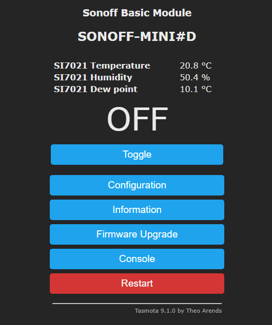
I'm running 9.1 on a Sonoff Mini with an AM2301 connected red=5V, black=gnd, yellow=GPI02 with 4.7k pull up.
When I set GPI02 to AM2301, I get three null values.
However when I set it to SI7021 it works.
On Sunday, 31 October 2021 at 10:23:36 UTC knowles...@gmail.com wrote:
Please read the thread. It's a AM2302 that's the issue and it worked until a change in Tasmota
Phil Gilbert
Philip Knowles
No worries.
The AM2301 is equivalent to the DHT11 & DHT21
The AM2302 is equivalent to the DHT22 and the SI17021
If your device is working as SI1702 it may likely be an AM2302 inside.
When I set GPI02 to AM2301, I get three null values.
However when I set it to SI7021 it works.
On Sunday, 31 October 2021 at 10:23:36 UTC knowles...@gmail.com wrote:
To view this discussion on the web, visit https://groups.google.com/d/msgid/sonoffusers/91fa2490-898d-4179-9c37-743f7eddc20fn%40googlegroups.com.