
Max

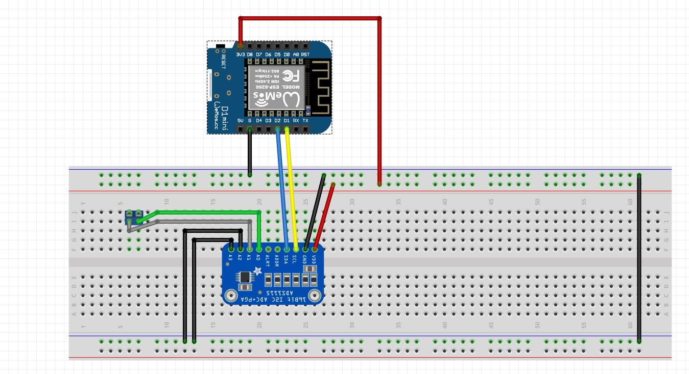
As you can see in the picture, I can see the four value coming from the ADS1115 but they are not stable, they continue change, and this happened with or without connect something to one of the four port.
So I thought it was a problem of my module.
I connect to a Arduino Uno and it work perfectly.
So I connect to a Wemos D1 R2 without Tasmota and it works perfectly.
Anybody use the ADS1115 or have any experience on that?
Thanks
Max

Philip Knowles
Sent: Monday, August 17, 2020 5:18:03 AM
To: TasmotaUsers <sonof...@googlegroups.com>
Subject: ESP8266 and ADS1115
You received this message because you are subscribed to the Google Groups "TasmotaUsers" group.
To unsubscribe from this group and stop receiving emails from it, send an email to sonoffusers...@googlegroups.com.
To view this discussion on the web, visit https://groups.google.com/d/msgid/sonoffusers/db938750-e6fc-4006-9933-3e349a10c7cfo%40googlegroups.com.
Max
Philip Knowles
Connect a 1k and 2k5 resistor in series. Connect the 2k5 resistor to 3.3V and the 1k to 0V and the centre point to an input and see what you get.
Regards
Phil K
Sent from Mail for Windows 10
--
You received this message because you are subscribed to the Google Groups "TasmotaUsers" group.
To unsubscribe from this group and stop receiving emails from it, send an email to sonoffusers...@googlegroups.com.
To view this discussion on the web, visit https://groups.google.com/d/msgid/sonoffusers/d2342b8f-27d2-45e7-bf90-1e96dfbf1e7bo%40googlegroups.com.
Max
Il giorno lunedì 17 agosto 2020 20:29:05 UTC+12, Philip Knowles ha scritto:
Connect a 1k and 2k5 resistor in series. Connect the 2k5 resistor to 3.3V and the 1k to 0V and the centre point to an input and see what you get.
Regards
Phil K
Sent from Mail for Windows 10
From: Max
Sent: 17 August 2020 06:22
To: TasmotaUsers
Subject: Re: ESP8266 and ADS1115
Hi Phil,
I'm using
tasmota-sensors.bin
Max
Il giorno lunedì 17 agosto 2020 16:51:18 UTC+12, Philip Knowles ha scritto:
--
You received this message because you are subscribed to the Google Groups "TasmotaUsers" group.
To unsubscribe from this group and stop receiving emails from it, send an email to sonof...@googlegroups.com.
Philip Knowles
To: TasmotaUsers <sonof...@googlegroups.com>
To view this discussion on the web, visit https://groups.google.com/d/msgid/sonoffusers/f4244b0e-aaf2-4691-a130-58fc049d3530o%40googlegroups.com.
Max
To view this discussion on the web, visit https://groups.google.com/d/msgid/sonoffusers/f4244b0e-aaf2-4691-a130-58fc049d3530o%40googlegroups.com.
Philip Knowles
To view this discussion on the web, visit https://groups.google.com/d/msgid/sonoffusers/5775abb7-420a-470f-909e-00ed4c0809e4o%40googlegroups.com.
Max


Unfortunately it will not be stable...probably there is something else
So I tried to connect A0 with A1, same result, they ae not stable, they move less than before, but they are not stable.
So I tried to connect A1 to GND and leave A0 open,nothing connect on it...Almost stable, it move a litlle bit.
To view this discussion on the web, visit https://groups.google.com/d/msgid/sonoffusers/5775abb7-420a-470f-909e-00ed4c0809e4o%40googlegroups.com.
Philip Knowles
To view this discussion on the web, visit https://groups.google.com/d/msgid/sonoffusers/ed353d0b-c5fc-4b7d-91dc-28df56c3487do%40googlegroups.com.
Max

To view this discussion on the web, visit https://groups.google.com/d/msgid/sonoffusers/ed353d0b-c5fc-4b7d-91dc-28df56c3487do%40googlegroups.com.
Philip Knowles
To view this discussion on the web, visit https://groups.google.com/d/msgid/sonoffusers/83b9e88f-b8c0-486f-a13f-7637d44d4cf8o%40googlegroups.com.
Philip Knowles
Meant to say that you need to do the maths. The whole point of using the differential measurement is to cancel out the noise so you need to subtract one from the other and the result may be more stable.
Regards
Phil K
Sent from Mail for Windows 10
From: Max
Sent: 20 August 2020 05:20
To: TasmotaUsers
Subject: Re: ESP8266 and ADS1115
Hi Phil.
I tried to connect a 50A shunt.
Here the connection
This is the Shunt 50A/75mV. The red connections go to A0 and A1 of the ADS1115.
Max
Il giorno mercoledì 19 agosto 2020 15:34:57 UTC+12, Philip Knowles ha scritto:
Sorry, what exactly are you connecting to it?
Model number would help.
Regards
Phil K
Sent from Outlook Mobile
From: sonof...@googlegroups.com <sonof...@googlegroups.com> on behalf of Max <y2k...@gmail.com>
Sent: Wednesday, August 19, 2020 12:21:20 AM
To: TasmotaUsers <sonof...@googlegroups.com>
Subject: Re: ESP8266 and ADS1115
Phil,
just here the connection:
- A0 to one part of the shunt;
- A1 to the other part of the shunt;
- A2 to GND
- A3 to GND


Unfortunately it will not be stable...probably there is something else
So I tried to connect A0 with A1, same result, they ae not stable, they move less than before, but they are not stable.
So I tried to connect A1 to GND and leave A0 open,nothing connect on it...Almost stable, it move a litlle bit.
Max
Il giorno martedì 18 agosto 2020 18:22:10 UTC+12, Philip Knowles ha scritto:
Just connect the unused inputs to 0V and they will be stable. An unused input will act like an aerial and can pick up noise.
Regards
Phil K
Sent from Outlook Mobile
From: sonof...@googlegroups.com <sonof...@googlegroups.com> on behalf of Max <y2k...@gmail.com>
Sent: Tuesday, August 18, 2020 7:05:37 AM
To: TasmotaUsers <sonof...@googlegroups.com>
Subject: Re: ESP8266 and ADS1115
Phil
so if I understan what you are telling me...
I have to connect all the 4 input to something otherwise anything will float?
I would like to connect on the 4 input, two shunt 30A/75mA.
What do you think?
Max
Il giorno martedì 18 agosto 2020 17:12:39 UTC+12, Philip Knowles ha scritto:
That value would give you approximately 1.03V at the input - a little bit of drift around the value is normal. It looks like the scaling is around 14000 per volt.
If the other inputs are not connected to anything they can float all over the place.
Regards
Phil K
To unsubscribe from this group and stop receiving emails from it, send an email to sonoffusers...@googlegroups.com.
To view this discussion on the web, visit https://groups.google.com/d/msgid/sonoffusers/83b9e88f-b8c0-486f-a13f-7637d44d4cf8o%40googlegroups.com.
Max


To view this discussion on the web, visit https://groups.google.com/d/msgid/sonoffusers/83b9e88f-b8c0-486f-a13f-7637d44d4cf8o%40googlegroups.com.
Philip Knowles
To view this discussion on the web, visit https://groups.google.com/d/msgid/sonoffusers/fadf0753-dca6-425b-85de-98984d91f337o%40googlegroups.com.

Justin Adie
On 22 Aug 2020, at 07:25, Philip Knowles <knowles...@gmail.com> wrote:
Ok. Was the wiring the same (I don't mean connections the same but the wiring route).
When you connected the resistors you were getting 14272 as a reading for 1.03V. That would give you a scale of roughly 14 per mV. For 0.83A on a 50A/75mV shunt you should get 1.2mV which would give you a reading of 17. The readings are nowhere near that so there is something interfering. If you aren't using a twisted pair/shielded cable trying to measure 1.2mV accurately will be almost impossible.
Based on the reading you got with your resistor I suspect the formula is incorrect too. Your formula is giving a reading of roughly 3 per mV.
Once you get a stable reading I would try connecting an car indicator bulb (21W) to a 12V battery. Depending on the state of charge you should get between 1.65 - 1.75A (measure the battery voltage to be accurate) which would give you around 2.5mV across the shunt.
If your formula is correct you would get a reading of about 9. Based on what you got with the resistors I think you'd get 36.
The ADS1115 has a programmable and Arduino and Tasmota may be using different gains which may explain the 4x difference.
Regards
Phil K
Sent from Outlook Mobile
From: sonof...@googlegroups.com <sonof...@googlegroups.com> on behalf of Max <y2k...@gmail.com>
Sent: Saturday, August 22, 2020 4:02:03 AM
To: TasmotaUsers <sonof...@googlegroups.com>
Subject: Re: ESP8266 and ADS1115
Hi Phil,thank for your help, but I do my home work.
I applyed the same formula that I've already use on Arduino Uno with success:amps = ((A0-A1) * 256.0) / 32768.0;//100mv shuntamps = amps * 1.333; //for 75mv shunt
I use this formula on Nore-Red and the result are:
<Immagine.jpg>
If I apply the same configuration and math formula on Arduino Uno or another ESP8266 with IDE the results are:
To view this discussion on the web, visit https://groups.google.com/d/msgid/sonoffusers/DB7PR02MB49197943375C55A7347E556EF7580%40DB7PR02MB4919.eurprd02.prod.outlook.com.
Philip Knowles
Sent: Saturday, August 22, 2020 9:42:51 AM
To: Max <y2k...@gmail.com>
Cc: TasmotaUsers <sonof...@googlegroups.com>; Philip Knowles <knowles...@gmail.com>