Smoothie board power supply?
700 views
Skip to first unread message

Adam Lindsay
Dec 14, 2013, 5:53:30 PM12/14/13
to smoothiewa...@googlegroups.com
Does anyone know the correct power supply for the five axis smoothie board running 2a steppers?

Chris Harvie-Smith
Dec 14, 2013, 6:18:20 PM12/14/13
to smoothiewa...@googlegroups.com
Be very careful with the connections !
Both a 5V for logic & 12V or 24V for steppers are required.
My USB seems to be 4.6V at the other end of the board with just a long usb lead supplying the 5V
The main power pins go +--+ that is VBB Ground Ground +5V
The +-+- are for the holes not the sockets!


More useful stuff here
For those looking at the connector yes it is similar to a Ramps it will fit but kill the board instantly if you were to use it.
Chris Harvie-Smith
Dec 14, 2013, 6:19:41 PM12/14/13
to smoothiewa...@googlegroups.com
I'm using 24V for the 2A steppers I have.
Adam Lindsay
Dec 27, 2013, 1:39:46 PM12/27/13
to smoothiewa...@googlegroups.com
Thanks for the reply! What amp power supplies are you using?
Chris Harvie-Smith
Dec 27, 2013, 3:12:10 PM12/27/13
to smoothiewa...@googlegroups.com
My steppers & hot end are on a 10 A 24V PSU
400 W bed heater & always on case fans are on a 400W PSU (17 A)
Also I have a temporary 5V 2.5A supply for smoothie 5V.
Including the Graphic lcd it's taking 150mA idle from the 5V PSU.
The whole board is 3.3V logic so actually runs fine when the usb lead drops the voltage to 4.6V
But the GLCD needs closer to 5V so I'm using a psu for now & will get a dcdc converter for the regulator position on the board next to VBB lettering.
If you are using an encoder (click wheel) then you need to re-map to avoid 1.22 & 1.23 as they do the two green switched outputs on a corner near VBB.
I asked Arthur & the pair nearby was:
panel.encoder_a_pin 3.25!^ # encoder pin
panel.encoder_b_pin 3.26!^ # encoder pin
Need to solder a few header strips to use these.
It's nearly ready to try a print ! It homes, heats & moves correctly :-)
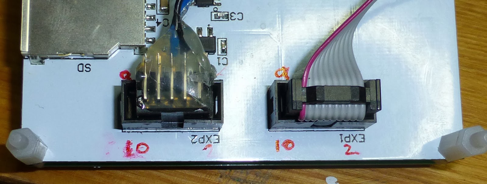
I'm glad I'm paranoid with circuity the reprap discount displays/panels connectors are backwards


400 W bed heater & always on case fans are on a 400W PSU (17 A)
Also I have a temporary 5V 2.5A supply for smoothie 5V.
Including the Graphic lcd it's taking 150mA idle from the 5V PSU.
The whole board is 3.3V logic so actually runs fine when the usb lead drops the voltage to 4.6V
But the GLCD needs closer to 5V so I'm using a psu for now & will get a dcdc converter for the regulator position on the board next to VBB lettering.
If you are using an encoder (click wheel) then you need to re-map to avoid 1.22 & 1.23 as they do the two green switched outputs on a corner near VBB.
I asked Arthur & the pair nearby was:
panel.encoder_a_pin 3.25!^ # encoder pin
panel.encoder_b_pin 3.26!^ # encoder pin
Need to solder a few header strips to use these.
It's nearly ready to try a print ! It homes, heats & moves correctly :-)

Red stripe on idc cable & little triangles on mating halves indicate pin 1 next to the red 10 !
Chris Harvie-Smith
Dec 27, 2013, 4:54:54 PM12/27/13
to smoothiewa...@googlegroups.com
The second picture was/is in the show quoted text bit so repeated here
Chris Harvie-Smith
Dec 27, 2013, 5:18:25 PM12/27/13
to smoothiewa...@googlegroups.com
Most useful hardware starting page is here http://smoothieware.org/smoothieboard
Scroll down to the coloured lines showing connections.
The green fitted power connector is + - - +
The small empty holes are - + - +
So don't use the silk screen for one to connect to the other.
The green socket covers up the + silkscreened text.
I'd start with 5V USB & data so you can see the board is working & you can get the driver installed & working for your pc win/lin/mac
From here http://smoothieware.org/
For seeing the switch leds light you'll need to supply vbb to the main input & either fit the jumpers or wire in both PWR_IN's & then use the config file to set the switches you want to control
Reply all
Reply to author
Forward
0 new messages